prestige aps25c, 2011 nissan sentra
Printed From: the12volt.com
Forum Name: Car Security and Convenience
Forum Discription: Car Alarms, Keyless Entries, Remote Starters, Immobilizer Bypasses, Sensors, Door Locks, Window Modules, Heated Mirrors, Heated Seats, etc.
URL: https://www.the12volt.com/installbay/forum_posts.asp?tid=125457
Printed Date: April 29, 2026 at 7:09 AM
Topic: prestige aps25c, 2011 nissan sentra
Posted By: craigmri
Subject: prestige aps25c, 2011 nissan sentra
Date Posted: January 04, 2011 at 6:46 PM
Hey guys, getting ready to install a Prestige APS25C in my sons new 2011 Nissan Sentra. While I have installed keyless entrys in the past, I've never installed a full alarm/keyless system.
I have found a document that suggests what and where to tap but I have some questions......
1) Obviously the siren installs in the engine compartment and the brain goes under the dash somewhere but where is the best location for the shock sensor?
2) I never feel totally confident with those 3M quick tap thingies. Are there any other methods for easy tap-ing or will I be soldering? If I solder, whats the best method to strip a harness wire to I can solder the alarm wire on without cutting the car harness wire?
If anyone has any advice for me regarding any part of the install I would greatly appreciate it.
Craig
Brooksville, FL
Replies:
Posted By: x1le
Date Posted: January 04, 2011 at 8:23 PM
you want to mount the shock sensor to the firmest thing possible. I like to tie strap it to metal if possible. If not then a thick wire harness will do.
If you want to solder then invest in a pair of side/automatic strippers. They will strip the insulation and leave the wire intact.
Posted By: tedmond
Date Posted: January 04, 2011 at 8:47 PM
) Obviously the siren installs in the engine compartment and the brain goes under the dash somewhere but where is the best location for the shock sensor?
i always use zip ties and connect it to a large harness, never had any problems with sensitivity.
2) I never feel totally confident with those 3M quick tap thingies. Are there any other methods for easy tap-ing or will I be soldering? If I solder, whats the best method to strip a harness wire to I can solder the alarm wire on without cutting the car harness wire?
solder your connections, its the best way. get yourself a good pair of wire strippers, make 2 cuts with the wire stripper, about half an inch from one another, then use a knife (olfa) and cut from one end to the other of each wire cut. Peel the insulation back and connect your wire/solder.
Tape it up with 3m superscotch 33+, sure its expensive but your "normal" electrical tape isnt cold weather friendly ------------- Ted
2nd Year Tier 1 Medical School
Still installing as a hobby...pays for groceries
Compustar Expert
Posted By: craigmri
Date Posted: January 06, 2011 at 7:53 PM
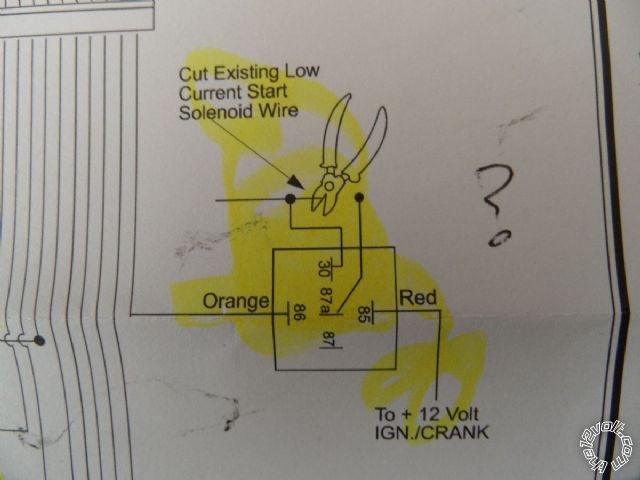
Thanks for the reply guys! Got the alarm and am about to move forward with the installation. One last confusion before I can continue and it relates to the starter interrupt. There is a relay I need to wire in. I basically cut the starter solenoid wire coming from the ignition switch and wire it to the appropriate relay connections. The alarm sends the relay a ground signal and finally I have to send the relay a Ignition switched 12V.
According to the attached document, is it the White Starter wire I cut? In addition, will I use the yellow ignition wife to provide the 12V for the relay?
Sentra Wiring
Thanks in advance guys!
Posted By: lectricguy
Date Posted: January 06, 2011 at 8:16 PM
According to the attached document, is it the White Starter wire I cut?
Yes.
In addition, will I use the yellow ignition wife to provide the 12V for the relay?
Yes.
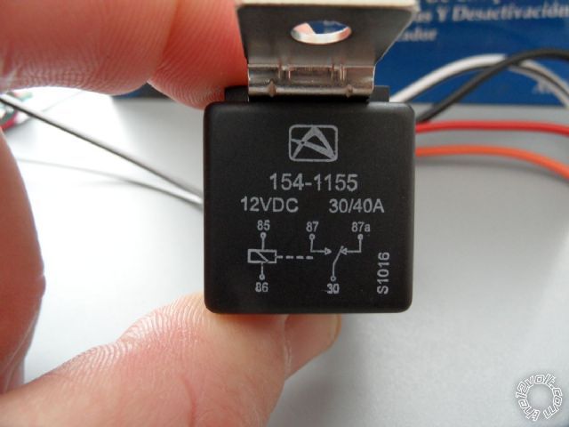
Based on the Relay Audiovox provides with its Alarm Systems, wire the relay as follows:
Pin 85 (Red) to Sentra Ignition (Yellow)
Pin 86 (Orange) to Orange Ground When Armed of APS25C
Pin 30 (BLACK/ White) to Sentra White (Key Cylinder side of cut wire)
Pin 87a (Black) to Sentra White (Starter Motor side of cut wire) ------------- Lectric Guy
Posted By: craigmri
Date Posted: January 07, 2011 at 3:31 AM
Thank you Lectric!!!
Craig
Posted By: tedmond
Date Posted: January 07, 2011 at 2:11 PM
if Howie II read this, he would have wanted you to wire it ISO standards.
85 - ground when running/starter kill output (-) from unit
86 - ignition (+)
87a - starter wire cut key side (towards key cylinder)
30 - starter wire cut motor side (towards engine bay) ------------- Ted
2nd Year Tier 1 Medical School
Still installing as a hobby...pays for groceries
Compustar Expert
Posted By: craigmri
Date Posted: January 07, 2011 at 3:06 PM
Ted,
Are you sure I should wire that way? According to the relay and Audiovox doc it says otherwise....Or am I missing something?
Craig
Posted By: lectricguy
Date Posted: January 07, 2011 at 3:31 PM
I went through this with Howie on a previous post (link below). Audiovox's relay socket has a built-in diode across 85 & 86, with the Cathode (band) toward 85; As a result, power must be on Pin 85(Red), and GWA on Pin 86(Orange)--Do Not reverse the recommended wiring of these leads on the Audiovox socket.
Pins 87a & 30 could be changed if you wanted, no impact.
The proper wiring for the Sentra application is listed here, which is consistant with Audiovox's install guide and the same as my earlier post:
Pin 85 (Red) to Sentra Ignition (Yellow)
Pin 86 (Orange) to Orange Ground When Armed of APS25C
Pin 30 (BLACK/ White) to Sentra White (Key Cylinder side of cut wire)
Pin 87a (Black) to Sentra White (Starter Motor side of cut wire)
https://www.the12volt.com/installbay/forum_posts.asp?tid=121349&KW=lectricguy ------------- Lectric Guy
Posted By: craigmri
Date Posted: January 07, 2011 at 9:46 PM
OK I think I have a better understanding now....Your both right! I checked a bosch document. Howie is right on that ordinarily ground and 12V of the coil side are interchangeable with one exception....if there is a diode across them which there is so your right Lectric!
Thanks for all your help with this. Its been a while since I exercised my electrical theory.
I'll be sure to follow up tomorrow with the progress of the install.
Craig
Posted By: craigmri
Date Posted: January 08, 2011 at 2:25 PM
OK I think I have all wires identified! The wire colors are wrong for the door lock, unlock and parking lights.
Question, I found a wire the goes hot when locking and a second wire that goes hot when un-locking. I assume these are my wires however I was under the impression it would be a ground signal to actuate the locks not 12V for our 2011 Nissan Sentra. The docs I'm working with are for 2007-2010. I didn't think they changed the car for 2011 but maybe they did??
If I measure resistance on both the lock and unlock wires to ground I get about 12 Ohms. I assume I'm reading through the locking motors?
Any thoughts?
Craig
Posted By: lectricguy
Date Posted: January 08, 2011 at 2:49 PM
|

|
Power Unlock |
|
PINK |
|
(-) |
|
IN HARNESS IN DRIVER KICKPANEL TO DOOR |
|
|
|
PowerLock |
|
RED |
|
(-) |
|
IN HARNESS IN DRIVER KICKPANEL TO DOOR |
These are the wires listed for the 2011. I would look for the harness from the driver's door, follow it to the kick panel, then test the wires while pressing lock or unlock. Sounds like you found the lock motors. they should be in the same harness from the door.
|
Driver Mtr Unlock |
|
GREEN |
|
(REV) |
|
IN HARNESS IN DRIVER KICKPANEL TO DOOR |
|
|
|
Driver Mtr Lock |
|
VIOLET |
|
(REV) |
|
IN HARNESS IN DRIVER KICKPANEL TO DOOR |
The listed wires for lock/unlock are from the driver's door switch. There is also a brown lock, and white unlock in the same harness that comes from the Driver's key cylinder. These are both negative (Active ground) signals; lock requires 1 pulse, the unlock will require a double pulse. ------------- Lectric Guy
Posted By: craigmri
Date Posted: January 08, 2011 at 2:59 PM
Lectric, I'm gonna owe you big time after this is done!
So you suggest I should see a ground signal on the Red and pink wires (assuming I can find them coming from the door) when I press lock /unlock respectively?
Craig
lectricguy wrote:
<TABLE id=ResultsTable style="BORDER-RIGHT: 0px; BORDER-TOP: 0px; BORDER-LEFT: 0px; WIDTH: 100%; BORDER-BOTTOM: 0px; BORDER-COLLAPSE: collapse" cellSpacing=0 cellPadding=0>
<T>
<TR>
<TD vAlign=center align=middle>
<IMG onclick="javascript WinDefinitionOpen400, 300, 251, 2885;" src="../../images/invisible.gif"> </TD>
<TD vAlign=center align=left><SPAN class=arial10pt>Power Unlock</SPAN></TD>
<TD style="WIDTH: 10px; HEIGHT: 20px" vAlign=center align=left></TD>
<TD vAlign=center align=left><SPAN class=arial10pt>PINK</SPAN></TD>
<TD style="WIDTH: 10px; HEIGHT: 20px" vAlign=center align=left></TD>
<TD vAlign=center align=left><SPAN class=arial10pt>(-)</SPAN></TD>
<TD style="WIDTH: 10px; HEIGHT: 20px" vAlign=center align=left></TD>
<TD vAlign=center align=left><SPAN class=arial10pt>IN HARNESS IN DRIVER KICKPANEL TO DOOR</SPAN></TD>
<TD style="WIDTH: 10px; HEIGHT: 20px" vAlign=center align=left></TD>
<TD vAlign=center align=middle></TD></TR>
<TR style="BACKGROUND-COLOR: #eeeeee">
<TD vAlign=center align=middle><IMG onclick="javascript WinDefinitionOpen400, 300, 251, 2886;" src="../../images/invisible.gif"></TD>
<TD vAlign=center align=left><SPAN class=arial10pt>PowerLock</SPAN></TD>
<TD style="WIDTH: 10px; HEIGHT: 20px" vAlign=center align=left></TD>
<TD vAlign=center align=left><SPAN class=arial10pt>RED</SPAN></TD>
<TD style="WIDTH: 10px; HEIGHT: 20px" vAlign=center align=left></TD>
<TD vAlign=center align=left><SPAN class=arial10pt>(-)</SPAN></TD>
<TD style="WIDTH: 10px; HEIGHT: 20px" vAlign=center align=left></TD>
<TD vAlign=center align=left><SPAN class=arial10pt>IN HARNESS IN DRIVER KICKPANEL TO DOOR</SPAN></TD></TR></T></TABLE>
These are the wires listed for the 2011. I would look for the harness from the driver's door, follow it to the kick panel, then test the wires while pressing lock or unlock. Sounds like you found the lock motors. thy should be in the same harness from the door.
<TABLE id=ResultsTable style="BORDER-RIGHT: 0px; BORDER-TOP: 0px; BORDER-LEFT: 0px; WIDTH: 100%; BORDER-BOTTOM: 0px; BORDER-COLLAPSE: collapse" cellSpacing=0 cellPadding=0>
<T>
<TR>
<TD vAlign=center align=middle><IMG onclick="javascript WinDefinitionOpen400, 300, 251, 2889;" src="../../images/invisible.gif"></TD>
<TD vAlign=center align=left><SPAN class=arial10pt>Driver Mtr Unlock</SPAN></TD>
<TD style="WIDTH: 10px; HEIGHT: 20px" vAlign=center align=left></TD>
<TD vAlign=center align=left><SPAN class=arial10pt>GREEN</SPAN></TD>
<TD style="WIDTH: 10px; HEIGHT: 20px" vAlign=center align=left></TD>
<TD vAlign=center align=left><SPAN class=arial10pt>(REV)</SPAN></TD>
<TD style="WIDTH: 10px; HEIGHT: 20px" vAlign=center align=left></TD>
<TD vAlign=center align=left><SPAN class=arial10pt>IN HARNESS IN DRIVER KICKPANEL TO DOOR</SPAN></TD>
<TD style="WIDTH: 10px; HEIGHT: 20px" vAlign=center align=left></TD>
<TD vAlign=center align=middle></TD></TR>
<TR style="BACKGROUND-COLOR: #eeeeee">
<TD vAlign=center align=middle><IMG onclick="javascript WinDefinitionOpen400, 300, 251, 2890;" src="../../images/invisible.gif"></TD>
<TD vAlign=center align=left><SPAN class=arial10pt>Driver Mtr Lock</SPAN></TD>
<TD style="WIDTH: 10px; HEIGHT: 20px" vAlign=center align=left></TD>
<TD vAlign=center align=left><SPAN class=arial10pt>VIOLET</SPAN></TD>
<TD style="WIDTH: 10px; HEIGHT: 20px" vAlign=center align=left></TD>
<TD vAlign=center align=left><SPAN class=arial10pt>(REV)</SPAN></TD>
<TD style="WIDTH: 10px; HEIGHT: 20px" vAlign=center align=left></TD>
<TD vAlign=center align=left><SPAN class=arial10pt>IN HARNESS IN DRIVER KICKPANEL TO DOOR</SPAN></TD></TR></T></TABLE>
Posted By: lectricguy
Date Posted: January 08, 2011 at 3:05 PM
Correct. These are connected to the driver's door lock/unlock switch.
I was editing my post when you replied....Also, the alternate Brown & White key cylinder wires should test as ground when you turn the key in the driver's door cylinder to lock or unlock. ------------- Lectric Guy
Posted By: craigmri
Date Posted: January 08, 2011 at 3:26 PM
Lec,
Found the correct harness coming from the drivers door! You were 100% correct! I got hung up from the wiring schedule stating it was the harness in kick panel that runs to rear of car.....The lock/unlock wires were in a harness tucked in a recess under the dash(coming from the drivers door).
Now I can focus on terminating everything. Are you of the strip/solder/tape camp or do you recommend another method?
Finally, if I may ask, what do you do for a living? I'm totally blown away that you would spend so much time helping out a guy you've never met before. Sharing your experience, expertise and guidance. I come away thinking that A) you love car electrics B) you like helping people and C) your extremely proficient at what you do. A,B and C!
THANK YOU!
Craig
lectricguy wrote:
Correct. These are connected to the driver's door lock/unlock switch.
I was editing my post when you replied....Also, the alternate Brown & White key cylinder wires should test as ground when you turn the key in the driver's door cylinder to lock or unlock.
Posted By: lectricguy
Date Posted: January 08, 2011 at 3:41 PM
craigmri-
Thanks for the compliment!
As far as making reliable connections, you can't beat soldering and then taping with 3M Scotch Super 33+ electrical tape (33+ is far superior to normal vinyl electrical tape, as it withstands a wide temperature range---Available in Home Depot).
I am an electrical engineer by trade, but really enjoy 12V electronics--If I can help someone out, even better.
Glad to hear that you identified all your wires--let us know how the end result works for you. ------------- Lectric Guy
Posted By: craigmri
Date Posted: January 09, 2011 at 2:06 PM
Installation complete now onto programming!! Lec do you have any experience getting into the programming mode on the Audiovox? I tried following the directions but they are confusing to me. Any advice?
Craig
Posted By: lectricguy
Date Posted: January 09, 2011 at 3:04 PM
Yes, I've done a ton of Audiovox.
1.) Make sure the system is unlocked.
2.) turn the ignition key to the "on" position (past accessory, before start).
3.) press the programming button 3 times--you will hear 1 chirp from the horn. You are now in bank 1, for adding or deleting transmitters.
4.) You advance to the next bank (Bank 2--for Alarm feature programming) by turning the ignition to the "Off Position, then back to "On". You will hear the horn honk as the ignition transitions to off, then a long honk as it transitions again to on. You are now in bank 2.
5.) You now select which feature you want to change by pressing the valet button; Each press the horn will honk indicating the settings--I.e., if the default is listed as 2 chirps, the horn will honk twice.
6.)If you want to change that setting, press the Lock button on your transmitter--you will hear the honks for the next setting--in this example 3 honks. If that is the desired setting, press the valet button to progress to the next feature; if you want to change to a different setting, press the lock button until the desired setting has benn selected.
7.) When you are done, you can turn the ignition off, and wait 15 seconds--the unit will exit programming mode.
Once you get the hang of it, the Avox programming is really fairly easy. Let me know if you need more info. ------------- Lectric Guy
Posted By: craigmri
Date Posted: January 10, 2011 at 10:02 AM
OK that makes much more sense Lec.....I just tried it again and believe I am in the correct mode now and as I would press the valet button it would give me a double honk for each feature until I reached what I think that the 6th feature(the one I want to change to voltage sense) and it sounds a long chirp and the lock button on the fib does nothing. I think the long chip indicates it ending programming? I'm missing a step somewhere.
Craig
lectricguy wrote:
Yes, I've done a ton of Audiovox.
1.) Make sure the system is unlocked.
2.) turn the ignition key to the "on" position (past accessory, before start).
3.) press the programming button 3 times--you will hear 1 chirp from the horn. You are now in bank 1, for adding or deleting transmitters.
4.) You advance to the next bank (Bank 2--for Alarm feature programming) by turning the ignition to the "Off Position, then back to "On". You will hear the horn honk as the ignition transitions to off, then a long honk as it transitions again to on. You are now in bank 2.
5.) You now select which feature you want to change by pressing the valet button; Each press the horn will honk indicating the settings--I.e., if the default is listed as 2 chirps, the horn will honk twice.
6.)If you want to change that setting, press the Lock button on your transmitter--you will hear the honks for the next setting--in this example 3 honks. If that is the desired setting, press the valet button to progress to the next feature; if you want to change to a different setting, press the lock button until the desired setting has benn selected.
7.) When you are done, you can turn the ignition off, and wait 15 seconds--the unit will exit programming mode.
Once you get the hang of it, the Avox programming is really fairly easy. Let me know if you need more info.
Posted By: lectricguy
Date Posted: January 10, 2011 at 11:31 AM
Craig-
There is a.requirement to go from bank 1 to bank 2 in (if iI recall correctly) 3 seconds. Then once in bank2, there is a 15Second inactivity time--if there is no action, the system will exit program mode.
So let's take this slow...
1.) Assuming the system is unlocked, turn the key to "on, press the valet button 3x. You get 1 honk from the horn.
2.) Within 3 seconds, turn the ignition key to "off" then immediately to "On" again. You will hear 2 honks, one at off, one at on.
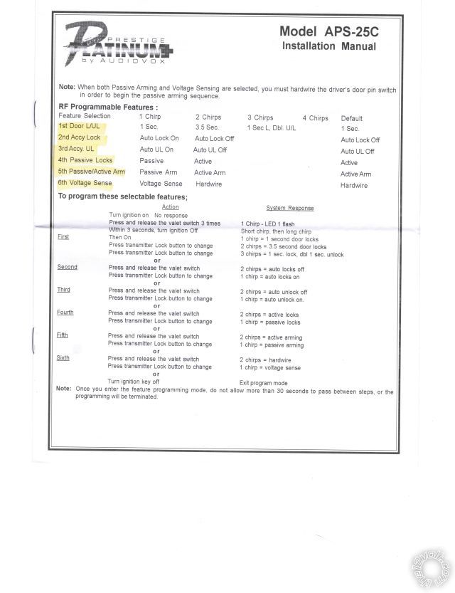
3.) Now, assuming your APS25C is in default settings, press the valet (PBLED) once for Feature 1--Door L/UL--It should be default at 1Sec--You will hear 1 honk (Refer to your sheet above--1 sec setting under the 1 chirp column, default setting 1 sec).
--If you want to change this, press lock--2 chirps would be heard (3.5Sec setting), press lock again, 3 chirps are heard (1 sec lock,/doubl U/L), etc. Once you have the appropriate setting selected, go to the next feature.
The next feature (Feature 2, Accy Lock)) is accessed by pressing the valet (PBLED) again. The default of feature 2 is 2 chirps, Auto Lock Off, so you
should hear 2 chirps. If this is the desired setting, Press the valet/PBLED again, to move to Feature 3, Accy UL.
Feature 3 (accy UL) default is 2 chirps, auto lock off, so you should hear 2 chirps.
You cycle through the features and settings this way until you are configured as desired. If you wait longer than 15S between steps, the system will exit program mode--with a long chirp, and you need to reenable bank 2 programming mode to continue (i.e., start again at step 1 above).
Hope this helps. ------------- Lectric Guy
Posted By: craigmri
Date Posted: January 10, 2011 at 11:54 AM
Lec,
Thank you for clearing all this up for me. I'm pretty sure I understand it all now. It only seems like I have 5 features to program and not six but perhaps I'm timing out like you suggest.
I'll try again again report back by tomorrow.
Cannot thank you enough!
Craig
Posted By: craigmri
Date Posted: January 12, 2011 at 3:51 PM
We're all set! I was able to change from hardwire to voltage sense. Now when I arm the alarm while sitting inside the car and manually turn on the dome light the alarm instantly triggers.
Lec, Thank you so much for holding my hand throughout my install. Thanks to your help I have a quality install.
Craig
|