2006 honda ridgeline remote start
Printed From: the12volt.com
Forum Name: Car Security and Convenience
Forum Discription: Car Alarms, Keyless Entries, Remote Starters, Immobilizer Bypasses, Sensors, Door Locks, Window Modules, Heated Mirrors, Heated Seats, etc.
URL: https://www.the12volt.com/installbay/forum_posts.asp?tid=125744
Printed Date: May 14, 2026 at 6:18 PM
Topic: 2006 honda ridgeline remote start
Posted By: stm144
Subject: 2006 honda ridgeline remote start
Date Posted: January 19, 2011 at 10:28 AM
I am planning on installing the Avital 5303L 2-way remote start on my 2006 Honda Ridgeline RTL. I am also planning on using the idatalink ADS-DLSL-HA module.
I have attached the wiring reference guides from both the Avital remote start and the iDatalink module below. With these I have included my notes. I was hoping someone could take a quick look over my pics with notes and let me know if I am missing anything.
This is what I came up with and is shown on the pictures:
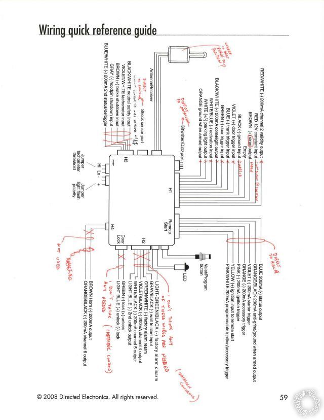
Picture 1 (Remote Start)
H1(needed wires)
H1/2 (Red 12V constant input, connect to white at IGN)
H1/3 (Brown Siren Output, connect to siren)
H1/5 (Black ground input, connect to chassis ground)
H2(needed wires)
None (all controlled by iDatalink)
H3(needed wires)
None (all controlled by iDatalink)
H4(needed wires)
None (or is this where I wire the siren in)
Bitwriter/D2D Port
Cord directly to iDatalink
Remote Start
Cord directly to Relay
Door Lock
None (all controlled by iDatalink)
Jumpers
Will I need to touch these settings?
Shock Sensor
Direct to sensor (zip tie sensor to wire harness)
Antenna/Receiver
Plan on mounting behind rear view (or does anyone have any other suggestions
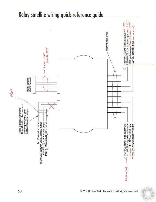
Picture 2 (Relay)
4 wire ribbon harness (not used)
Relay Satellite
Cord directly from Remote Start
Heavy Gauge Wires
Purple & Green
Connect to appropriate side of BLACK/ White @ IGN
Red (Both) & RED / White
Connect to White @ IGN
Orange
Connect to Yellow @ IGN
Pink/White
Not Used
Pink
BLACK / YELLOW @ IGN
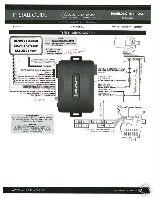
Picture 3 (iDatalink)
D2D Wire
Direct to Remote Start
All other connections on left side
Not Used
WHITE/ Black Security Light Input to Key Side Blue Orange @ IGN
WHITE/ Red Security Light Output to Car Side Blue Orange @ IGN
ORANGE / Black Key Data to RED / Blue @ IGN
Orange Door Data to Brown Black @ loc 4 of 21 pin connector found at Drivers Door
Pink Ignition to BLACK/ Green @ IGN
Please someone take a look and let me know if I am missing something or if I am wiring something wrong. Thanks for your time, it is greatly appreciated!
Replies:
Posted By: gabedemelo
Date Posted: January 19, 2011 at 11:19 AM
i wouldnt use the data plug i would advise you to butt connect etc all the connections between remote start and idatalink,... ive been installing remote starts for close to 15 years and when data bypasses became available i started using the data harnesses and even tho it saves time at first there would always be at least 1 output each time that didnt carry the proper data. then you have to rewire anyway. xpresskits were the worst as far as the data harness.
-------------
GreenGables
Posted By: gabedemelo
Date Posted: January 19, 2011 at 11:27 AM
use horn beep instead of siren they are harder for thieves to remove haha,.. place antenna where you said but leave inch and half below lining so you can unplug easy incase you have to replace without damaging harness,... after install is done and shock sensor is mounted turn all the way down then turn up slightly, they are always too sensitive and if people hear alarm all the time they will ignore if or when something actually happens.
-------------
GreenGables
Posted By: stm144
Date Posted: January 19, 2011 at 11:41 AM
Do you really think I will run into problems with just using the D2D connection with the iDatalink? In all the research I've done and the people I've talked to that used them, they haven't had any problems.
Does my wiring look correct other than your recommendations?
Posted By: stm144
Date Posted: January 19, 2011 at 6:46 PM
Has anyone had the data connect issues with the idatalink products? I could do the connections On the bench before install but wouldnt I also run the tach wire. Would there also be other wires I would have to then hard wire in.
Also, has anyone seen any issues in my wiring? Thanks in advance!!!
Posted By: Twelvoltz
Date Posted: January 19, 2011 at 7:41 PM
First, and this might cause quite a few people to voice their own opinions, NEVER butt connect any connections for a remote starter installation. Solder everything...no exceptions IMO.
To the question about using D2D...The Idata pieces work great with D2D as long as the piece you are connecting to works fine with D2D. But, I have never had any luck with the Avital brand and their D2D connection. 99% of the remote starters I install are Avital. I would strongly recommend using the W2W connections.
-------------
Installer, IT support, and FFL. I need less hobbies.
Posted By: stm144
Date Posted: January 19, 2011 at 8:28 PM
I think im going to try the d2d first and if i have trouble with it i will go w2w. If I do the w2w do I have to run a tach output wire?
Do you think the newer remote starts and bypass modules have a better shot at working? Both of mine were made in late 2010 and have the most current software. I'm hoping to get by using the d2d
Posted By: tedmond
Date Posted: January 20, 2011 at 9:01 AM
x1 with twelvoltz, solder all the way. butt connectors fail over time. im sur esoldering takes less time than butt connectors.
im sure the d2d for idatalink does not work with any directed modules, so you will have to w2w anyways.
Since the idatalink modules were made specifically for compustar units (such as the blade) i dont think it works with any dei, but will with other companies. Likewise for xpresskits, it wont work on a compustar through data (i tried and tested) but no luck. ------------- Ted
2nd Year Tier 1 Medical School
Still installing as a hobby...pays for groceries
Compustar Expert
Posted By: stm144
Date Posted: January 20, 2011 at 12:22 PM
everyone seems to think that d2d wont work with the avital unit? but has anyone actually tried one in the last year?
Everyone including the people at iDatalink say that it will work. They told me that they previously ran into problems when trying to use their product with the d2d to dbi cable (for DEI remote starters) but for the last year or so most DEI starters have the d2d connection and should be compatible. Has anyone tried and failed with the d2d and a new avital or any other dei unit with d2d. Thanks
Posted By: Twelvoltz
Date Posted: January 20, 2011 at 3:19 PM
It may work...since you have the 5303L...it definitely does NOT work on the 4113/4111/4103 units.
stm144 wrote:
everyone seems to think that d2d wont work with the avital unit? but has anyone actually tried one in the last year?
Exactly how long do you think the people on here go between installs?
Listen, hook it up the way you want it's your system. You asked advice, it was given, do what you want with it. I for one am hoping it works. ------------- Installer, IT support, and FFL. I need less hobbies.
Posted By: stm144
Date Posted: January 20, 2011 at 4:01 PM
All I meant was that maybe the people who have responded and stated that all they use is w2w because they found out that d2d previously gave them headaches haven't tried to wire one up d2d for a while.
I understand that alot/most of you guys are professionals and do tons of work. That being said I know how I do things and if something doesn't work the first time chances are I will stay with the method that works. Sorry if I offended anyone.
Since it may be easier to just w2w it on the bench could someone please fill me in on the which wires from the avital need to be hooked up to the idatalink and which wires they need to go to. I think I have a basic idea on this just don't want to mess it up.
idatalink wire connects to RS Wire
Blue/White-----------------???
Black----------------------Chassis Ground
Red------------------------White (IGN)
GREEN/ Black----------------???
Blue/Black-----------------???
RED / White------------------???
Brown----------------------Light GREEN/ Black
Purple / YELLOW--------------GREEN / WHITE and Green
Purple Black---------------not used
White----------------------not used
BLACK/ White----------------???
Green----------------------???
PURPLE / White---------------Violet/White
Yellow (Hood)--------------Gray
Thank you.
Posted By: pimpincavy
Date Posted: January 20, 2011 at 4:24 PM
I have on occasion had problems with the D2D on the idatalink modules. On a few vehicles the locks would randomly lock and unlock while the customer was driving the vehicle. Did it W2W and the cars never came back. This was when using a Crimestopper remote start.
Posted By: stm144
Date Posted: January 21, 2011 at 9:02 AM
Can someone take a quick look at my wiring for wire to wire between avital 5303 and idatalink ads-dlsl-ha and give me some input.
The images for the diagram are with my first post. Thanks!!!
This is my thinking
idatalink wire connects to RS Wire
Blue/White-----------------???
Black----------------------Chassis Ground
Red------------------------White (IGN)
GREEN/ Black----------------???
Blue/Black-----------------???
RED / White------------------???
Brown----------------------Light GREEN/ Black
Purple / YELLOW--------------GREEN / WHITE and Green
Purple Black---------------not used
White----------------------not used
BLACK/ White----------------???
Green----------------------???
PURPLE / White---------------Violet/White
Yellow (Hood)--------------Gray
Posted By: kreg357
Date Posted: January 21, 2011 at 11:07 AM
idatalink wire connects to RS Wire
Blue/White-----------------Remote Start Harness Blue (-) 200mA Status Output
Black------------------------Chassis Ground
Red--------------------------White (+12v constant) @ ignition harness
GREEN/ Black----------------Door Lock Harness - Green
Blue/Black------------------Door Lock Harness - Blue
RED / White------------------Not Used on Ridgeline - iDatalink bypass does not support trunk release
Brown-----------------------H2 Light GREEN/ Black
Purple / YELLOW--------------not used Sliding door
Purple Black---------------not used sliding door
White------------------------not used
BLACK/ White----------------Starter Wire BLACK/ White @ ignition harness
Green-----------------------H1/ Green
PURPLE / White---------------H3 Violet/White
Yellow (Hood)--------------H3 Gray Verify vehicle has factory hood switch and vehicle shuts down when hood is raised during remote start. ------------- Soldering is fun!
Posted By: stm144
Date Posted: January 21, 2011 at 11:20 AM
thanks kreg...
with this setup i do not need to make any additional connection hardwired into the car other than the 6 heavy gauge and 4 bypass wires correct? I'm just trying to make sure I am not missing something. Things like dome light, parking light, that is still controlled by the idatalink?
Thanks again
Posted By: kreg357
Date Posted: January 21, 2011 at 11:55 AM
There are some connections necessary from the Viper to the Ridgeline besides the remote starter ground, power wires, one IGN, one Starter and two ACCs'. The iDatalink module does not control the Parking Lights.
H1/ White Parking Lights Set to (-) Polarity and connect to Blue(-) wire at Headlight Switch - Green 6 Pin Plug
H3/ Brown Brake Input to Light Blue(+) wire at brake pedal switch.
H3/ BLACK/ White Neutral Safety connection to GREEN/ ORANGE (-) AT SWITCH AT BASE OF PARKING BRAKE LEVER.
Dome lights should not be necessary if the lights come on with a factory remote unlock command.
Horn is not necessary if you use the siren. ------------- Soldering is fun!
Posted By: stm144
Date Posted: January 21, 2011 at 12:06 PM
thanks again kreg,
you've been a great help! my brother and I are going to be installing this tonight and I am hoping that I have all the info that I need. I've done plenty of radio installs and other 12v accessories but never a remote start so this should be fun.
Hopefully this thread will be of some help to people in the future and hopefully I won't have to come back here with problems!!!
If you have any final word of wisdom please feel free to share them with me.
Thanks again!
Posted By: kreg357
Date Posted: January 21, 2011 at 1:01 PM
Some more thoughts. Go W2W between the Avital and bypass. The Avital uses DBI D2D protocol and I am not sure if a Solo series bypass from iDatalink has that protocol or just the standard iDatalink RS232 protocol.
Follow the iDatalink ADS DLSL HA guide for Type 1 install. Page 3 has the wire colors listed and should be very accurate. Page 4 has diagrams of the vehicles' connectors.
I am not familial with the Avital units but if it is similar to the Viper models, you will need to do some programming. Going by the Avital 5303 Install Guide in the Downloads section...
Menu 3, Item 1, Option 4 for Tach mode.
Menu 3, Item 6, Option 2 for Pink/White = ACC2
Menu 3, Item 3, Option 2 ( IMHO, I don't like the Parking Lights flashing during remote start run time.)
Page 32 of the 5303 Install guide has the Tach Learn procedure. This must be done before you can have a successful remote start.
Also, as mentioned above, the Ridgeline has two Accessory wires. The WHITE/ Black ACC2 wire should be powered by the Pink/White wire from the Satellite Relays. The programming change above will set that Pink/White wire correctly to ACC2.
All wires should be verified with a Digital Multi Meter. As Twelvoltz pointed out, all connections should be soldered and well insulated with quality electric tape ( Scotch Super 33+ ). ------------- Soldering is fun!
Posted By: stm144
Date Posted: January 21, 2011 at 1:29 PM
you have the light blue wire at brake pedal switch to connect to the brown (H3) for brake shutdown input.
I have in my notes that should be WHITE/ black for my 2006 Honda Ridgeline.
Can you double check that for me.
Thanks
Posted By: kreg357
Date Posted: January 21, 2011 at 1:52 PM
You could be right on the Brake (+) wire. Bulldog Securities has it as Light Blue (+) but Audiovox and DirectWire have it as WHITE/ Black. This just reinforces the advice to verify all wires with a DMM. The wire guide lists are only guides...( and the DMM never lies )
Another place to get the { WHITE/ Black } Brake (+) wire is at the fuse box, White 45 Pin Plug, Pin 26. { According to DEI } ------------- Soldering is fun!
|