viper 5901, 2004 ford ranger
Printed From: the12volt.com
Forum Name: Car Security and Convenience
Forum Discription: Car Alarms, Keyless Entries, Remote Starters, Immobilizer Bypasses, Sensors, Door Locks, Window Modules, Heated Mirrors, Heated Seats, etc.
URL: https://www.the12volt.com/installbay/forum_posts.asp?tid=125775
Printed Date: May 16, 2026 at 3:32 PM
Topic: viper 5901, 2004 ford ranger
Posted By: chaddaddy
Subject: viper 5901, 2004 ford ranger
Date Posted: January 21, 2011 at 11:45 AM
I just bought a viper 5901 and im installing it on a 2004 Ford ranger 5 speed. My question is first, what wires do i connect to 12V constant? Can I just run these straight to the battery? Also the I have the green, purple, orange, and pink wires all done that was pretty easy but Im very confused about all the rest of them? any input is greatly appreciated
Replies:
Posted By: chaddaddy
Date Posted: January 21, 2011 at 11:51 AM
Also I got a harness that has 18 wires on it. What is this one for I dont see it in the instal manual???
Posted By: t&t tech
Date Posted: January 21, 2011 at 7:09 PM
List your wire s and we'll tell you what to do! All the heavy reds can connect to the 12 constant at the ignition harness,
PINK- IGNITION
ORANGE- ACCESSORY
PINK/WHITE- 1ST IGNITION
GREEN- STRTER KEY SIDE
PURPLE - STARTER ENGINE SIDE
PINK/BLACK- CUT AND ISOLATE.
Posted By: kreg357
Date Posted: January 21, 2011 at 8:26 PM
Looks like you have the new and improved Viper 5901. They moved some wires around on you. The 18 Pin harness is H2. Here is a pin-out.
H2/1- LHT GRN/BLK (-) 200mA OEM ALARM DISARM OUTPUT
H2/2- ORG/BLK (-) 200mA AUX 4 OUTPUT
H2/3- GRN/WHT (-) 200mA OEM ALARM ARM OUTPUT
H2/4- VIOL/BLK (-) 200mA AUX 2 OUTPUT
H2/5- WHT/BLK (-) 200mA AUX 3 OUTPUT
H2/6- WHT/VIOL (-) 200mA AUX 1 OUTPUT
H2/7- GRY/BLK (-) 200mA DIESEL WAIT TO START
H2/8- BRW/BLK (-) 200mA HORN HONK OUTPUT
H2/9- VIOL/WHT TACHOMETER INPUT
H2/10- DRK BLU (-) 200mA STATUS OUTPUT
H2/11- PINK/WHT (-) 200mA FLEX RELAY CONTROL OUTPUT
H2/12- ORG (-) 200mA ACC OUTPUT
H2/13- PRPL (-) 200mA STARTER OUTPUT
H2/14- PINK (-) 200mA IGNITION 1 OUTPUT
H2/15- GRY (-) 200mA HOOD PIN INPUT (N/C N/O)
H2/16- BLU/WHT (-) 200mA 2ND STATUS/REAR DEFFOGER OUTPUT
H2/17- BRW (+) BRAKE SHUTDOWN INPUT
H2/18- BLK/WHT (-) NEUTRAL SAFETY INPUT
------------- Soldering is fun!
Posted By: chaddaddy
Date Posted: January 21, 2011 at 10:37 PM
Ok cool thanks man. So I dont have to use the RED wire then? Just the ink and white? And whats the difference between Ignition 1 and 2?
Also with the 18 wire harness. I hate to be a pest but can you explain what those are for, where they go, and which ones ARE ABSOLUTELY NECESSARY!
Thanks a bunch for the input.
Posted By: dragonpntr
Date Posted: January 21, 2011 at 11:22 PM
H2/1- LHT GRN/BLK (-) 200mA OEM ALARM DISARM OUTPUT / Goes to GREEN/ purple in driver door boot -
H2/10- DRK BLU (-) 200mA STATUS OUTPUT / To ground when running on security module
H2/17- BRW (+) BRAKE SHUTDOWN INPUT / Lt. Green at brake pedal +
H2/18- BLK/WHT (-) NEUTRAL SAFETY INPUT / Ground
Red, RED / white, and RED / black if you have it go to the large yellow wires at the ignition switch
Clutch bypass is pink at the switch and is +
You do not need the disarm wire if the truck does not have power locks or factory alarm. You can check for the alarm by locking the door while open with the switch then closing it. Wait about 5 min. then open the door without using the key if the horn honks it has an alarm.
Posted By: chaddaddy
Date Posted: January 22, 2011 at 12:33 AM
Ok then the truck didn't come with power locks, windows, or an alarm. It has an anti theft system though. So is H2/1 needed and if so where do i connect it? What about H1/3?
With the Red, RED / white, and RED / black let me ask you this. Look at the picture below. What yellow wire.....theres four... hahah. 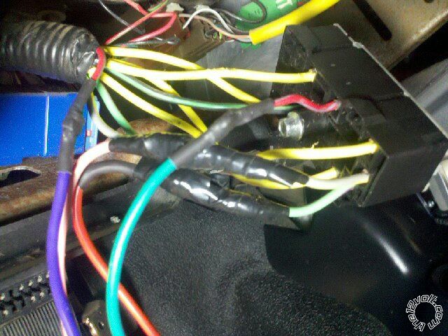
Posted By: dragonpntr
Date Posted: January 22, 2011 at 2:16 AM
There is 4 of them they all are constant hook up your 3 constant powers to 3 of them also your large pink/white should go to the gray / YELLOW and change it in the programing to an acc.
pink to GREEN/ purple
orange to BLACK/ green
red to 1 yellow
RED / white to 1 yellow
RED / black to 1 yellow
You won't need H 2/1
To do the immobilizer you will need a security module or if you don't mind losing a key you could make a bypass here is a link to a document. https://www.the12volt.com/installbay/file.asp?ID=610
Posted By: chaddaddy
Date Posted: January 22, 2011 at 3:31 AM
Alright cool thanks man. So the following ones Im having trouble with : H2/2,34,5,6,9,10,11,12,13,14,16 I just need to know what there for and where they hook up to if they can be hooked up at all.
Thaks for all your help im slowly getting this thing finished :)
Posted By: chaddaddy
Date Posted: January 22, 2011 at 4:34 AM
Also, I am hooking up the clutch bypass and the ebake right now.... im lost... what wires do i use and how do i connect them?
Posted By: kreg357
Date Posted: January 22, 2011 at 6:29 AM
The H2/18 Neutral Safety should be connected to the Parking Brake RED / YELLOW (-) @ vehicle Parking Brake Switch.
H3/9 Tach should be connected to Tachometer TAN/WHITE (-) AT IGNITION COIL.
H3/10 (-) Status Output goes to the bypass module Ground When Running input.
What brand / model of bypass module are you using?
The others H2/2,3,4,5,6,11,12,13,14,16 are not mandatory or are optional.
While I have never done a manual trans Ranger, if the info above is correct, here is how to bypass the clutch switch:
Buy a 30/40 A SPDT relay with harness and a 20 A inline fuse. Wire as follows:
H2/13 (-) Starter to Relay Pin 85.
+12v constant to Relay Pins 86 and 87 thru inline fuse.
Relay Pin 30 to Pink wire at clutch pedal switch.
Relay Pin 87a not used - insulate.
------------- Soldering is fun!
Posted By: dragonpntr
Date Posted: January 22, 2011 at 10:36 AM
Usually on ford rangers you can hook the purple starter wire to the pink at the clutch pedal and it will crank the truck. I totally spaced that this was a stick sorry. But I agree with kreg357 on the wiring and it would work with the relay also if you don't want to move your starter wires.
Posted By: chaddaddy
Date Posted: January 22, 2011 at 12:05 PM
Ok thanks. You guys are the best!! As of right now i haven't gotten a bypass unit. Any suggestions?
Posted By: kreg357
Date Posted: January 22, 2011 at 12:19 PM
Best bang for the buck is DEI 1100F bypass module. Available at "online auction" for about $12.
-------------
Soldering is fun!
Posted By: chaddaddy
Date Posted: January 22, 2011 at 1:36 PM
Ok so just to clear this up. I can hook up H3/4 to the pink clutch wire directly? no relays or anything? What is the difference between using the relay and not using it other that just more work to do?
Also, with the bypass unit. Do i have to have firmware "learning" software to make it "learn" my anti theft system loaded on to it or will it work right out of the box?
Posted By: kreg357
Date Posted: January 22, 2011 at 2:01 PM
Here is a link to the DEI 1100F guide : https://www.the12volt.com/installbay/file.asp?ID=696 It comes ready to go right out of the box. You will need two working, non-clone, keys to program it to your truck.
------------- Soldering is fun!
Posted By: chaddaddy
Date Posted: January 22, 2011 at 2:34 PM
Ok cool! Thanks you guys. Anyone have an answer to the question about the clutch in my previous post? Ok so im done with harness 2 and 3 and im about half way through harness 1
So Heres what i have so far.
H1/1: NA (no trunk)
H1/2: STRAIGHT TO BATTERY
H1/3: SIREN
H1/4: NEED HELP
H1/5: CHASSIS GROUND
H1/6: I HAVE A (-) DOOR SYSTEM SO?? NOT NEEDED?
H1/7: NA?? HELP PLEASE
H1/8: ON THIS ONE SINCE I HAVE TWO DOORS I JUST SPLIT THE WIRE INTO 2 AND CONNECTED ONE TO THE DRIVER SIDE WIRE AND THE OTHER TO THE PASSENGER SIDE. IS THAT OK?
H1/9: NEED HELP
H1/10: NEED HELP
H1/11: TO PARKING LIGHTS WIRE
H1/12: NEED HELP
So can you guys just double check this and help me with the ones i need help with?
Posted By: kreg357
Date Posted: January 22, 2011 at 6:29 PM
H1/1 RED / WHITE (-) 200mA TRUNK RELEASE OUTPUT No trunk
H1/2 RED (+)12v CONSTANT INPUT +12v constant
H1/3 BROWN (+) SIREN OUTPUT Siren
H1/4 WHITE/ BROWN LIGHT FLASH ISOLATION WIRE Not used
H1/5 BLACK (-) CHASSIS GROUND Chassis Ground
H1/6 VIOLET (+) DOOR TRIGGER INPUT Not Used Truck has (-) triggers
H1/7 BLUE (-) TRUNK PIN/ INSTANT TRIGGER INPUT No trunk
H1/8 GREEN (-) DOOR TRIGGER INPUT Connect to both door triggers & diode isolate with 1N4001
H1/9 BLACK/ WHITE (-) 200mA DOME LIGHT OUTPUT Not needed if dome light comes on with unlock
H1/10 WHITE/ BLUE (-) REMOTE START/ TURBO Not used
H1/11 WHITE PARKING LIGHT OUTPUT Set Jumper/Fuse accordingly (-) or (+) depending on the Parking Light wire used***
H1/12 ORANGE (-) 500mA GROUND WHEN ARMED OUTPUT Not used
-------------
Soldering is fun!
Posted By: chaddaddy
Date Posted: January 22, 2011 at 9:49 PM
Ok cool. SO H1/8 What do you mean connect it to a diode? And H1/11 i just change that with that fuse inside the brain correct? Also, the question about the clutch is still up if anyone knows.
Posted By: chaddaddy
Date Posted: January 22, 2011 at 9:53 PM
I just answered my own question about the diode. Other two I still need.
Posted By: kreg357
Date Posted: January 23, 2011 at 4:35 AM
2004 Ford Ranger Parking Light info:
Bulldog
PARKING LIGHTS ( - ) WHITE/ BLACK (-) @ SJB, Small BLACK Plug, Pin 16, See NOTE *1
PARKING LIGHTS ( + ) BROWN (+) @ SJB, BROWN Plug, Pin 8, See NOTE *1
Audiovox
Parking Lights BROWN (+) IN HARNESS IN DRIVERS KICKPANEL
Low Crr. Pk Lights WHITE/ BLACK (-) AT HEADLIGHT SWITCH
As noted there are several places and both polarities available for the remoter starter to connect
to the Rangers Parking Lights. Depending on which polarity you choose, you will set the Vipers
Fuse/Jumper accordingly to ensure the H1/11 White wire output is correct. The Parking Light
Fuse/Jumper is under the access door and inside the brain.
Here is some more info on the Door Trigger diode isolation from Bulldog :
https://www.bulldogsecurity.com/diagrams/extrainfo/diagrams/4698_Ranger_FORD%20DOOR%20PIN%20ISOLATION.pdf ------------- Soldering is fun!
Posted By: chaddaddy
Date Posted: January 23, 2011 at 12:52 PM
Ok so to clear this up a bit. I need to put a diode coming from the BCM to the trigger. between the diode and the trigger i need to put another diode and connect it to the RS wire. Correct?
Posted By: kreg357
Date Posted: January 23, 2011 at 4:04 PM
Yes, just follow the diagram. On Fords that have BCMs that shutdown to save power, you will get false alarms on your Viper if you don't diode isolate. One diode prevents the Viper from seeing the BCM shutdown, the other diode allows you to connect multiple door trigger inputs into one alarm input.
-------------
Soldering is fun!
Posted By: chaddaddy
Date Posted: January 23, 2011 at 4:26 PM
Yea I saw that. I just finished the instal! But your right, out of nowhere the alrm just starts going off saying "door open" All I have is the clutch which I still need help on if you can help me, the door triggers which I am ordering the diodes as we speak, and the bypass unit which I am also ordering right now.
Posted By: chaddaddy
Date Posted: January 25, 2011 at 3:42 PM
DO NOT TRY THE SHORTCUT THAT TIES THE PURPLE STARTER WIRE TO THE PINK CLUTCH WIRE!!!! Anyone who is thinking about doing this DO NOT DO IT!!! I just tried it and the truck went crazy!!. The horn was honking the lights were flashing and the key did not matter. I pulled it out of the vehicle and the car was still running and going crazy. I burnt the hell out of my clutch because I put it in gear and put the emergency brake on the stall the engine. With the key out the truck was still trying to start! This is a REALLY BAD IDEA!! So anyone reading this DO NOT DO IT!!!!
Posted By: smokeman1
Date Posted: January 29, 2011 at 7:25 AM
In ANY OF THIS, did you use a Digital Multi Meter to Test and VERIFY what wires you were connecting to??? In the download section of this site, download the Viper 5701 Install guide. Starting on page 13 is a section on how to find and test for the wires you need. Start over, but start there. Something is most likely not connect correctly.
-------------
When all else fails, Read the Instructions
Support the12volt.com Make a Donation
Posted By: chaddaddy
Date Posted: January 29, 2011 at 12:09 PM
I KNOW FOR SURE that every wire except for the clutch wire is connected correctly. I triple checked all of my wiring before I even plugged the brain in. It was working fine until i did the clutch bypass. The alarm worked great ( just need to get some diods to isolate the doors) The next day I did the clutch bypass and that's when all hell broke out. Once again, I installed the alarm on friday and the Remote start on saturday. So the remote start is what is messed up. I checked the ground, IGN, starter wire, ACC, and 12V, they were all good. The brain is still functioning somewhat correctly, it knows when the doors open, it knows the running lights are on, The blue light on the remote receiver doesn't do anything, the remote always comes back with a "FAILED" sign. So im wondering if that is bad? I am taking the brain itself to bestbuy to have them test it to make sure that it is good before I go any farther into anything.
Posted By: dragonpntr
Date Posted: January 30, 2011 at 3:50 PM
Interesting I just did that bypass last week and it worked just fine I have also used it many other times on rangers. If it would not shut off it sounds like your brake wire is not working. Does the truck have a factory alarm or is it a base model with no power option? If you test the pink wire it should show power when the clutch is pushed and the car is cranked.
Posted By: chaddaddy
Date Posted: February 01, 2011 at 10:01 PM
Wow that's very odd... I don't know what went wrong...? I mean as far as the 4 yellow wires in the IGN harness, they are all just a 12V constant right? That is the only thing I was fairly skeptical about. Kreg357 said there all the same so I took his word because he was so dead on about everything else. What do you think? And no the truck did not come with a factory alarm. And I cannot be sure of what happened... the brain is still going all crazy, I checked my ground and all other wires, again, and nothing helps. I have come to the conclusion that the brain just got toasted somehow. I sent it back to Dynamic autosound where I bought it and they had no problem sending me a new one. it'll be here Friday. I am having a friend of mine come over, he used to do these alarms professionally so we'll see what he thinks. I'm not sure, any input?
Posted By: kreg357
Date Posted: February 02, 2011 at 6:04 AM
dragonpntr wrote:
There is 4 of them they all are constant hook up your 3 constant powers to 3 of them also your large pink/white should go to the gray / YELLOW and change it in the programing to an acc.
pink to GREEN/ purple
orange to BLACK/ green
red to 1 yellow
RED / white to 1 yellow
RED / black to 1 yellow
You won't need H 2/1
To do the immobilizer you will need a security module or if you don't mind losing a key you could make a bypass here is a link to a document. https://www.the12volt.com/installbay/file.asp?ID=610
Wasn't me. Bulldog and Audiovox do not specify how many Yellow +12 volt constants are found at the ignition switch. DEI says only three. Of course everyone here supplying assistance agrees that all connections must be verified with a Digital Multi Meter. Car manufacturers often change things in the middle of the production run without notice so the wire guides are just that, only guides. ------------- Soldering is fun!
Posted By: chaddaddy
Date Posted: February 02, 2011 at 8:15 AM
Oh my bad kreg. Sorry about that. And yes I did. They ones i used all have 12v. I did check the with the DVOM. Well my buddy is going to look at it and we'll see what he has to say.
Posted By: chaddaddy
Date Posted: February 03, 2011 at 8:30 PM
Alright so I have some info here everyone. So the verdict is in. When this all happened I didn't smoke my clutch I smoked my starter. That is why the truck was still trying to start when it was in gear. So does anyone have any idea why it would do this and if so what can I do to fix it?
Posted By: dragonpntr
Date Posted: February 03, 2011 at 10:34 PM
I said the 4 yellows were 12v test them they should be. If your starter is staying engaged ether there is an ignition hooked up to the start wire, or the tach is not working if you used a tach if not make sure its in virtual tach or voltage sens in the programing. How did you end up doing the clutch bypass?
Posted By: t&t tech
Date Posted: February 04, 2011 at 5:22 AM
Haven't read through this entire thread, but hey after smoking a starter, maybe it might just be cheaper to consult a professional.
Posted By: chaddaddy
Date Posted: February 04, 2011 at 6:57 AM
T&t, I am having a professional come over today, good friend of mine. And I was thinking that last night dragon. I will have to check the tach. The guy who worked on my truck said that it was about time fora starterr anyways so just avoided breaking down on the road. Ill keep you all updated.
Posted By: chaddaddy
Date Posted: February 04, 2011 at 5:51 PM
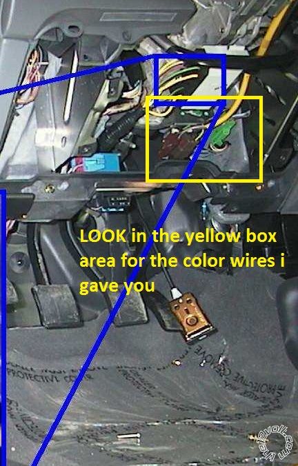
Does anyone know where the key harness is. I bought the DEI1100 bypass but I am having trouble finding the "C" connector as indicated in the manual. Any tips on where to find this?
Posted By: kreg357
Date Posted: February 04, 2011 at 6:01 PM
This info from the iDatalink ADS TB FM install guide.
TX RX
Pin Color Pin Color Connector
Ranger 01-06 4 WHITE/ LtGreen 3 Gray/Orange Type C
Connectors A and C are found 8 inches lower on PATS harness.
Look for the connector 8 inches down the steering column from the ignition switch. ------------- Soldering is fun!
Posted By: moonliter
Date Posted: February 04, 2011 at 6:14 PM
Posted By: chaddaddy
Date Posted: February 04, 2011 at 8:42 PM
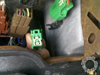
Is it this one? it leads straight to a small black box with a chip inside underneath the key. When I unplug it the anti theft light comes on and no start. But just to double check because it looks nothing like the C connector shown on the DEI instructions....?
Posted By: chaddaddy
Date Posted: February 04, 2011 at 8:44 PM
There is a WHITE/ lt. green and a ORANGE / gray in te conector.
Posted By: kreg357
Date Posted: February 04, 2011 at 9:18 PM
Yes, that is the connector. To verify, download the ADS TB FM Install guide, ##4738##, from the iDatalink WEB site, https://www.idatalink.com/helpdesk/ . Page 7 has a diagram of the connectors. ------------- Soldering is fun!
Posted By: chaddaddy
Date Posted: February 05, 2011 at 8:36 AM
Ok cool thanks got that working. Question though, does anyone know where i can get a pair of decent power door locks that aren't going to cost me $200?
Posted By: howie ll
Date Posted: February 05, 2011 at 11:20 AM
Try Googling Spal, Radio Shack, MES, DEI all the major alarm manufacturers, $200? Nearer $20.
-------------
Amateurs assume, don't test and have problems; pros test first. I am not a free install service.
Read the installation manual, do a search here or online for your vehicle wiring before posting.
Posted By: chaddaddy
Date Posted: February 07, 2011 at 8:24 AM
Ok so everything is done. The only thing that is giving me trouble s the DEI 1100F bypass.I do the programming as ordered but after the 1st step the LED goes red for like 1/32 of a second and then goes green solid for 2 seconds and it does nothing after that. I reset and did remote start again and it worked, once, then i shut RS off and tried agin, no go the security anti theft light was blinking on the dash....? any ideas?
Posted By: chaddaddy
Date Posted: February 07, 2011 at 5:58 PM
Ok never mind I got it. I tried it one more time and it worked. Everything is great I just have to isolate the doors and its done. :)
|