I am attempting an install of a Crimestopper CS-2003DC II in my 1998 Chevy Malibu.
I found wiring color codes for both, but there are several that don't make sense.
Crimestopper:
https://www.crimestopper.com/Templates/support/techweb/InstructionBooks/Alarm/cs2003dc_2d_ins_ops.pdf
Malibu:
https://www.the12volt.com/installbay/alarmdetail/544.html
If anyone can point me in the right direction, it would be greatly appreciated.
I understand and know the locations of the following so far:
Pin 5: Red (+12V Power in) to Constant +12V Red
Pin 7: Violet (Door Trigger) to Door Trigger Lt GREEN/ Black
Pin 8: Black (Ground) to frame under dash
Pin 9: White (+12V parking light) to Parking Light Brown wire
Pin 14: Blue (- Hood/Trunk Trigger) to Trunk release Black
Then the obvious blue and red connectors that go to the led and override button, as well as the 4-pin wire to the shock sensor.
There were two different wire harnesses for the 3-pin jack on the unit, one which went to a coupler that has an additional white, dark green, blue, red, and black wire in addition to the r/g/b wires, and the other just ended with the r/g/b wires. The coupler is a large black piece with what appear to be female spade connectors inside.
I'm pretty sure about the 5-pin jack which I will wire into my door lock with the positive trigger configuration.
For the power to the device, does it just use the RED / black wires from the 15-pin harness? There are two spade connectors, one of which I assume goes to the hood pin which are throwing me off. Are those the power connections or just one is used for the hood pin?
Then finally the large brown wire which I assume goes to the hood pin safety feature. There are two spade connectors on the unit though and the manual does not say which one needs connected for it to work.
I am trying to learn all this myself, so please no 'Go have a professional install it.' comments.
I have gone almost 5 years without needing to take my car into a professional shop as I have done all the repairs and modifications myself. (installed a new door lock actuator just this morning)
I know this is a large question, so thank you very much for any help!
Green to lock (+)(lt.blue of car in DKP)
Blue to unlock (+) (White of car in DKP)
Must connect the Violet to +12V for positive door Locks
Yellow to ignition wire of car (Pink at key harness)
BROWN / white to horn wire of car (Black at steering column)
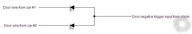
Green NOT purple ((-)Door trigger) to lt grn/blk & lt blue of car
Note: The lt. GREEN/ black is located in the drivers kick and catches only the drivers door. The lt. blue is located in the harness coming from the drivers running board going under the drivers seat and it catches all other doors. Use both door trigger wires and diode isolate each.
-------------
Sylvain Rochon
MECP security specialist
Tech support for remote starters
26 Years of experience counts
I'm here to help.