Viper 350, 530t, 2009 Dacia Logan
Printed From: the12volt.com
Forum Name: Car Security and Convenience
Forum Discription: Car Alarms, Keyless Entries, Remote Starters, Immobilizer Bypasses, Sensors, Door Locks, Window Modules, Heated Mirrors, Heated Seats, etc.
URL: https://www.the12volt.com/installbay/forum_posts.asp?tid=126650
Printed Date: April 25, 2026 at 7:10 PM
Topic: Viper 350, 530t, 2009 Dacia Logan
Posted By: cristu
Subject: Viper 350, 530t, 2009 Dacia Logan
Date Posted: March 19, 2011 at 12:51 PM
I need to connect an 12V / 20mA electroliminiscet led to my car.
When I stop the engine the led starts to blink and when I ran the engine the led stops. Can you provide an diagram how to connectit to my car ? Do I need to use an relay ? Can you make me the connections to my relay. Thank you.
Replies:
Posted By: oldspark
Date Posted: March 19, 2011 at 7:06 PM
I presume you mean you have a 12V 20mA flashing LED.
Connect the +ve end to battery +12V and the -ve end to IGN +12V.
There is no need for a relay (the relay will consume more power than the LED).
Posted By: cristu
Date Posted: March 20, 2011 at 1:28 AM
Yes it;s correct it's flashing LED.
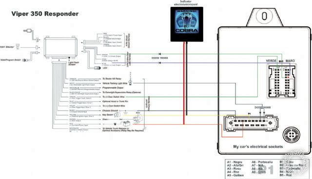
I want to integrate to my car's alarm (when I will mount it). It's Viper 350 Reponder alarm. I attached an diagram with the led connected.
It is correct how I made it ? Shoud I integrate an relay with the alarm ?
Thanks
Posted By: howie ll
Date Posted: March 20, 2011 at 2:22 AM
I can't clearly see your diagram but wire the red wire of the electroluminescent panel to your red 12V+ power wire of the alarm and the black to the alarm's orange GWA wire.
No relay needed because:
a) It will be drawing more power than the alarm ( x about 4).
b) It will flatten your battery during the time the alarm is armed.
-------------
Amateurs assume, don't test and have problems; pros test first. I am not a free install service.
Read the installation manual, do a search here or online for your vehicle wiring before posting.
Posted By: cristu
Date Posted: March 20, 2011 at 8:17 AM
Hi Howie
You mean H1/1 ORANGE (-) ground-when-armed output ?
From the alarm's manual: >> This wire supplies a (-) ground as long as the system is armed. This output ceases as soon as the system is disarmed. The orange wire is pre-wired to control the 8618 starter kill relay. It can supply up to 500 mA of current.
NOTE: If using the H1/1 Orange wire to activate an add-on accessory such
as window automation, or voice module a 1Amp diode must be installed to
ensure proper operation.
Should I install a diode on this wire (orange) or leave it just simple ?
Thanks
Posted By: howie ll
Date Posted: March 20, 2011 at 8:43 AM
Yes to the first question.
You will only need a diode if the GWA is powering other devices such as a window closer.
A diode (1N4004) in-line for each branch, towards the alarm.band or cathode
-------------
Amateurs assume, don't test and have problems; pros test first. I am not a free install service.
Read the installation manual, do a search here or online for your vehicle wiring before posting.
Posted By: cristu
Date Posted: March 21, 2011 at 6:18 AM
Hello
I want to connect an alarm system to my car and I want to do it myself. I have the diagram's alarm and I know where is the sockets/harness at my car.
I'm a novice regarding the electrical wires from a car so I want to identify and test the wires before soldering and other joins to do.
I have identified the red constant power input wire with a digital multimeter, the ground wire, the (+) after contact - key switch (yellow wire) but how can I identify and test the other wires (car's side): lock output (-), unlock output (-), door switch wire (-), vehicle parking light wire etc.
Can you tell me how to identify these wires with an multimeter ? or can I simulate the lock/unlock the doors with the multimeter or test light. Is there any tutorials or documentations regarding this matter
Thanks
Posted By: heinstal
Date Posted: March 21, 2011 at 7:37 AM
well cristu it depends on the car actually. Most of the time those wires can be found on the BCM or some juncion connector under the dash. once you have the car model look it up on this site under vehicle wiring at the top of the page. the door lock and unlock are usually negative triggered so you will see a 12 V voltage when using a multimeter and when the door lock is pushed it will go to 0.
BUT before testing wires look up their location on the site! ------------- ~~~WAEL~~~
Posted By: cristu
Date Posted: March 22, 2011 at 10:54 AM
Hi I make the scheme of Viper 350 Responder with the coonections to my car. Can You tell me if I connect the diodes correctly to wires ? and if the wires are ok ?
Thanks
Viper 350 Responder diagram
ftp://86.121.93.92:2020/Viper_350.pdf
Posted By: howie ll
Date Posted: March 22, 2011 at 3:54 PM
What car? Make model and year please.
-------------
Amateurs assume, don't test and have problems; pros test first. I am not a free install service.
Read the installation manual, do a search here or online for your vehicle wiring before posting.
Posted By: cristu
Date Posted: March 23, 2011 at 1:57 AM
It's a romanian car: DACIA LOGAN, 1.5 diesel, year 2009 (made by RENAULT factory). I do not find the wiring diagram on this site. I just want to know if the isolate diodes are mounted on the right direction on the wires for (-) door switch wire and vehicle parking lights.
Posted By: cristu
Date Posted: April 04, 2011 at 11:08 AM
Hi Howie II
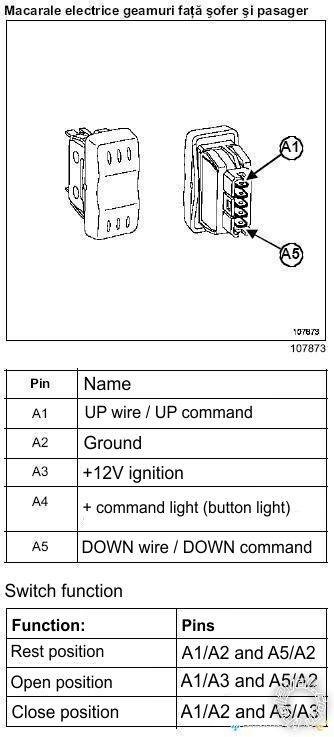
I have a DEI 530T system and I want to mount it on my car. I have the user instructions and I want to know witch type of window system I have on my car.
I attach you 2 images with the button diagram/wire meanings and motor.
When I turn on the engine I press the Up button > window UP and down button > window Down. The switch does not work if the engine is not running.I think is Type B - rest at +12V ignition but I'm not sure.
I appreciate if you look at the button's scheme and "light me up"
Thanks
Posted By: howie ll
Date Posted: April 04, 2011 at 11:12 AM
Actually, that's an after market kit, Spal etc. and it rests at ground.
-------------
Amateurs assume, don't test and have problems; pros test first. I am not a free install service.
Read the installation manual, do a search here or online for your vehicle wiring before posting.
Posted By: cristu
Date Posted: April 04, 2011 at 12:13 PM
You mean in my case the I have Type A window system ? rest at ground (-)
Posted By: howie ll
Date Posted: April 04, 2011 at 12:48 PM
Yes.
-------------
Amateurs assume, don't test and have problems; pros test first. I am not a free install service.
Read the installation manual, do a search here or online for your vehicle wiring before posting.
Posted By: cristu
Date Posted: April 13, 2011 at 6:21 AM
Hi Howie II,
I have draw a wiring scheme to connect DEI530T to my existing wires at my car. (page 2 on the pdf file linked)
As you told me, I have Type A window system (Rest at ground )
Can you please look at my draw to see if I made all the wiring connections right ?
One more thing: Should I connect the ground wires (black and violet) to the wire the comes to window switch (A2 - ground) or should I connect it to a chassis ground (bolt or other ground location to my car)
DEI530T Wiring (PDF)
Posted By: howie ll
Date Posted: April 13, 2011 at 11:38 AM
Exactly right, if you're mounting in the door, use the window switch ground not any bolts.
The correct way to wire this is to mount the unit in the car and lead out to both window motors, you will then have one touch up-down operation on both windows.
-------------
Amateurs assume, don't test and have problems; pros test first. I am not a free install service.
Read the installation manual, do a search here or online for your vehicle wiring before posting.
Posted By: cristu
Date Posted: April 13, 2011 at 11:56 AM
Thanks, I thought so about the location of the grounds.
The wiring scheme it's ok ? I mean do I correctly wire the leads from unit to my motor/switch wire ?
Posted By: howie ll
Date Posted: April 13, 2011 at 12:02 PM
Yes, all correct.
-------------
Amateurs assume, don't test and have problems; pros test first. I am not a free install service.
Read the installation manual, do a search here or online for your vehicle wiring before posting.
Posted By: cristu
Date Posted: April 18, 2011 at 8:58 AM
Hello,
I want to install an DEI 545T Nite-Lite system to my car and I need to know witch is the polarity of the vehicle's parking light and head light circuits.
I presume it's (+) 12V switched for both parking lights and headlights but I;, not sure of that. So I write you the light switch diagram to guide me to the right polarity
Thank You
Light switch pins & function:
-----------------------------
Pin Name
========================
A1 Fog lights
A2 N/A
A3 Back foglight
A4 Acustic warning
A5 Right signal
A6 Ground
A7 Left signal
B1 Parking lights
B2 Constant +12V parking lights
B3 Constant +12V HeadLight low-beam
B4 Headlights (double pltical unit)
B5 Headlights (simple optical unit)
B6 Constant +12V Headlight high-beam
B7 Headlights high-beam
Function:
Pin Command
=========================
A7/A6 Left signal on
A5/A6 Right signal on
B1/B2 Parking lights on
B5/B3 Headlights low-beam on
B5/B3/B7/B6 Headlights high-beam on
A1/B2/B1/B2 Foglights on
A3/B2/B1/B2 Rear foglight lamp
A4/B6 Acustic warning
Posted By: cristu
Date Posted: April 18, 2011 at 12:41 PM
Sorry oldspark, I thought that it's not necessary to start a new thread only for my question, so i searched for DEI 545t and post it to a related topic about this.
It's not a VW group Howie II, it's a Renault group (model Dacia Logan 1.5DCI, Year 2009, assembled in Romania/Eastern Europe)
I have the light switch wiring diagram witch I have post it above this message so I thought that if there's three Constant +12V for separate headlights (low-beam, high bean and parking lights) and each one goes to the specific wire/command I presume that's (+) 12V switched.
I will test it with a multimeter to make sure that I do not make some mistakes at my car wiring installation.
Thanks
Posted By: the12volt
Date Posted: April 18, 2011 at 3:40 PM
cristu, all of your posts regarding this installtion have been merged into this topic. Please do not add to old threads created by others for your own installation (aka hijacking). Please continue to post in this thread for anything related to this installation.
Thanks in advance. -------------  the12volt Support the12volt.com the12volt Support the12volt.com
Posted By: cristu
Date Posted: April 23, 2011 at 8:57 AM
Hello,
I have successfully installed a Viper 5002 security system on my car with 2 extra modules from DEI: Dei 508d proximity sensor and DEI 545t Automatic-Lights.
I have plugged the motion sensor on port Sensor 2 on the brain's alarm.
I want to install the DEI 530t module for my front windows. I know the wiring scheme from my car's windows but I'm not sure that it will not trigger the 508d when the windows roll up.
On the DEI 530t it's a wire H2/5 Gray (-): Output during activation. Connect this wire to optional relay P/N 610T to bypass sensors witch may trigger the security system during operation. this wire continues to output (-) ground for 5 seconds after the window motors have stopped.
How could I connect the relay to this wire and the 508d to bypass this sensor for 5 seconds ?
Thank You.
Posted By: howie ll
Date Posted: April 23, 2011 at 9:09 AM
Any small PCB relay such as the JM67X from Maplin Electronics, UK£1.67, around 2 Euros. Also DEI 8615, much cheaper than the one you quoted.
Grey to 85, 12V+ to 86, cut 508d black wire, then one side to 30, other side to 87a. You might try it initially without the relay, see if it affects the alarm.
-------------
Amateurs assume, don't test and have problems; pros test first. I am not a free install service.
Read the installation manual, do a search here or online for your vehicle wiring before posting.
Posted By: cristu
Date Posted: April 23, 2011 at 9:13 AM
Thanks Howie II. I'll try first without relay and see how it works.
Posted By: cristu
Date Posted: April 24, 2011 at 9:10 AM
I have one more thing to ask you. If I want to vent the windows should I disarm first, vent windows and rearm ? I assume the if I press the aux function for the 530t while the system is armed It will trigger the proximity sensor.
Is there a way to do this by first deactivate the 508d temporarily and reactivate after the command to vent windows is completed ? Thanks
I was wondering is this can be done with a relay P/N 610T or other:
- blue wire from dei 508d cut, one part to 30 the other to 87a
- 12V to 86
- auxiliary output (H2/5 Gray (-) to 85
But how about the green wire (warn away) from 508d ?!
I appreciate if you can help me with this.
Posted By: howie ll
Date Posted: April 24, 2011 at 9:52 AM
Again try it without the relay first, my original answer still stands and applies, the grey black activates on closing, venting and full opening.
-------------
Amateurs assume, don't test and have problems; pros test first. I am not a free install service.
Read the installation manual, do a search here or online for your vehicle wiring before posting.
Posted By: cristu
Date Posted: April 24, 2011 at 10:43 AM
Ok, I will try this.
I thought that the needs for relay applies only at closing.
If the sensor will trigger at venting I will connect the relay as you told me.
I'll let you know, probably in 1-2 weeks when I plan to mount the module. Thanks gain. Cheers.
Posted By: cristu
Date Posted: April 24, 2011 at 11:17 PM
Is there a way to add remote start to my viper 5002 alarm ? Witch module should I use ?
Posted By: howie ll
Date Posted: April 25, 2011 at 2:10 AM
If this is a manual transmission it shouldn't be done and in theory it can't be done.
Having said that can you access a pin-out guide to your engine management or the RFI "Chip" in your ignition key?
-------------
Amateurs assume, don't test and have problems; pros test first. I am not a free install service.
Read the installation manual, do a search here or online for your vehicle wiring before posting.
Posted By: cristu
Date Posted: April 25, 2011 at 7:26 AM
It's a manual trsnmission, diesel. Here at the localstores I find Viper Valet 561T start engine module. It seems that I will need an bypass trsnsponder for my ingnition key. I barely find the proper wires at my car so I think it's quite "not for me job". So I think I'll forget it, don't know yet.
Posted By: howie ll
Date Posted: April 25, 2011 at 7:37 AM
556U with a spare key for the by-pass, MTM for the transmission.
-------------
Amateurs assume, don't test and have problems; pros test first. I am not a free install service.
Read the installation manual, do a search here or online for your vehicle wiring before posting.
Posted By: cristu
Date Posted: April 28, 2011 at 11:00 AM
Today I received the DEI 530t module an I want to install it in the weekend. I talked to a friend about this and he told me that the motors from the windows door are not so powerfull and they could be damaged by this module ?! (Is it true ?). Meaning that when I arm the car and the windows are up, the 530t could force them and in time damage can occur. I think it's not true, 530t could sense that the windows are up and not trigger anymore. And If the windows are down, arm, windows rolling up ..and the motors are forced upon close ? This guy really freak me out. I do not want to burn my windows motors. Does the 530t knows when to stop it when windows are up ?
Posted By: howie ll
Date Posted: April 28, 2011 at 11:17 AM
Thermal cut-outs and timer, no problems. If your friend knows so much, why are you asking here? Yes I do have Romanians coming to me with their cars.
-------------
Amateurs assume, don't test and have problems; pros test first. I am not a free install service.
Read the installation manual, do a search here or online for your vehicle wiring before posting.
Posted By: cristu
Date Posted: April 28, 2011 at 11:38 AM
I am asking you to make sure that is no problem and the advices you gave me are from an expert; for this I'm graceful. Thanks
Posted By: cristu
Date Posted: April 28, 2011 at 11:37 PM
On my ground when armed wire from the alarm I hookup 2 wires : Black wire from my blinking led (Electro-Luminescent Indicator)and orange wire - ground when armed from the DEI 545t Nite-Lite module and here comes another orange wire from the DEI 530t module. Should I connect them all together ? should I use diodes ? In this case how can I connect the diodes ? Thanks
Posted By: howie ll
Date Posted: April 29, 2011 at 5:27 AM
Diodes on all, bands towards the alarm. Do you have a spare aux? Blue/white? Set that to a timed output, 2 secs. longer than it takes to close the windows, say 6-8 seconds, and run that to the 530t. That would therefore act as a safety timer for the 530t. Thus you have a timed cut-out AND the thermal cut-outs, double safety.
-------------
Amateurs assume, don't test and have problems; pros test first. I am not a free install service.
Read the installation manual, do a search here or online for your vehicle wiring before posting.
Posted By: cristu
Date Posted: April 29, 2011 at 9:21 AM
I have an spare aux H1/10 WHITE/ BLUE 200 mA (-) channel 3 output - validity output. But how can I set it to a timed output ?
In the Viper 5002's manual at Bitwriter Features, It says "Channel 3 Timed 190 seconds (30 seconds- factory default)". So I have the Channel 3 timed at 30 seconds ? I think Is not good setting, right ?
I do not have Bitwriter to set it proper.
Posted By: howie ll
Date Posted: April 29, 2011 at 9:23 AM
Set it manually via the programming, timed, about 8 seconds, you don't need a bitwriter.
-------------
Amateurs assume, don't test and have problems; pros test first. I am not a free install service.
Read the installation manual, do a search here or online for your vehicle wiring before posting.
Posted By: cristu
Date Posted: April 29, 2011 at 9:45 AM
But how can I set it manually ? Using Valet button ?
On Menu #3 - Advanced features at the 3-5 position I have Channel 3: Validity (One Chirp Setting) and latched/latched, reset with ignition/30-second/60-second/90-second timed/remote start report (Two chirp setting). How can I set it to 8 seconds timed ?
Posted By: howie ll
Date Posted: April 29, 2011 at 9:52 AM
Sorry, I didn't realise it was so basic, best bet, use the orange to trigger a 528t timer set to the time.
-------------
Amateurs assume, don't test and have problems; pros test first. I am not a free install service.
Read the installation manual, do a search here or online for your vehicle wiring before posting.
Posted By: cristu
Date Posted: April 29, 2011 at 10:43 AM
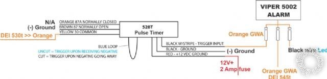
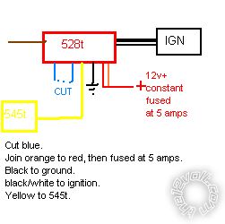
So you say that I should connect the orange wire from the DEI 530t to DEI 528t module ? Can you tell me the exact wiring connections ? Thanks. Should I cut the blue loop wire on DEI 528t ?
Posted By: howie ll
Date Posted: April 29, 2011 at 11:14 AM
Orange from alarm, dioded band to alarm, to BLACK/ white on 528t.
528t Red to 12V+ constant 2 amp fuse, black to ground.
Orange on 528t, don't use.
Brown to ground, yellow to orange on 530t, set the internal timer for the length of time stated in a previous post.
-------------
Amateurs assume, don't test and have problems; pros test first. I am not a free install service.
Read the installation manual, do a search here or online for your vehicle wiring before posting.
Posted By: cristu
Date Posted: April 29, 2011 at 1:09 PM
So this safety timer cuts off the (ground when armed) while windows are rolling up and down ?
Posted By: howie ll
Date Posted: April 29, 2011 at 1:34 PM
Yes, double safety if you're worried about what your friend told you. By the way DON'T cut the loop.
-------------
Amateurs assume, don't test and have problems; pros test first. I am not a free install service.
Read the installation manual, do a search here or online for your vehicle wiring before posting.
Posted By: cristu
Date Posted: April 30, 2011 at 1:27 PM
Today I have installed the DEI 530t window module and it works ok.
The only problem is that when I arm the car with windows down the 508d trigger. I have to put a relay as Howie II told me. Also Monday I will buy the DEI 528t Pulse Timer and attached to GWA wires (alarm and DEI 530t.
Posted By: cristu
Date Posted: May 02, 2011 at 4:51 AM
Seems that I need to install a relay on the DEI 508d because it's been trigger by the windows. If I roll up the windows (arm button) the 508d module starts to trigger and a strange thing happens: after I arm the car (with windows UP, no rolling) after 40-50 seconds the car start to chirp (warn-Away trigger), I think it's the dei 508d sensor.
This schematic it's ok ? What should I add to this diagram to prevent drain of battery ? or the relay is energized ONLY when it's triggered by gray wire from DEI 530t. 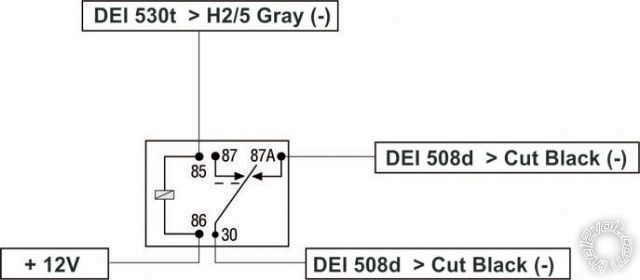
Posted By: howie ll
Date Posted: May 02, 2011 at 5:02 AM
Yes.
-------------
Amateurs assume, don't test and have problems; pros test first. I am not a free install service.
Read the installation manual, do a search here or online for your vehicle wiring before posting.
Posted By: cristu
Date Posted: May 04, 2011 at 11:10 AM
Hi,
I have attached an diagram with DEI 528t Pulse Timer (programmed 3 secs later after the windows roll up) connected to my alarm and DEI 530t windows module. Is it correct ? Another question: I have connected 12V+ red's from all modules (DEI 530t, DEI 545t, DEI 528t and relay for DEI 508d) and alarm at same source input. Should I use separate sources ? I really do not have multiple 12V+ sources under my dash board. I want to know if it's safe.
Posted By: howie ll
Date Posted: May 04, 2011 at 11:26 AM
That's fine as long as they are separately fused.
-------------
Amateurs assume, don't test and have problems; pros test first. I am not a free install service.
Read the installation manual, do a search here or online for your vehicle wiring before posting.
Posted By: cristu
Date Posted: May 18, 2011 at 8:58 AM
Finally I have fished my installation by adding DEi 528t Pulse Timer Relay to my windows module and a SPDT Relay to the dei 508d motion sensor. The only thing that's bothers me is that when I arm the car with windows all down, they roll up all way up, and at the top is trigger the shock sensor once (prewarn). I have adjusted the sensor less sensitive but useless. The shock it's quite strong for the alarm when the window meets the up door. Regarding the dei 508d sensor: I have added a diode across 85 and 86 pin (band toward to 86 - 12V+) to prevent some spikes and drain of battery. Is it correct ? Thanks.
Posted By: howie ll
Date Posted: May 18, 2011 at 9:27 AM
Yes but not necessary, can the shock sensor be delayed via the programme or if external delayed via the programming?
-------------
Amateurs assume, don't test and have problems; pros test first. I am not a free install service.
Read the installation manual, do a search here or online for your vehicle wiring before posting.
Posted By: cristu
Date Posted: May 18, 2011 at 9:54 AM
The shock sensor is built-in the brain's alarm (Viper 5002). I will check the installation manual to see if there is any chance to be delayed but I'm afraid it's not possible. If there's any other tricks to try let me know. Thanks.
Posted By: howie ll
Date Posted: May 18, 2011 at 10:01 AM
Only opening the damn brain and relaying it's power supply via the timed output from the 530t, but then, there goes the warrantee.
-------------
Amateurs assume, don't test and have problems; pros test first. I am not a free install service.
Read the installation manual, do a search here or online for your vehicle wiring before posting.
Posted By: cristu
Date Posted: May 18, 2011 at 10:18 AM
I have found something in the installation manual:
Bypassing Sensor Inputs:
There are times when you need to temporarily bypass all sensor inputs to the unit, such as when activating the windows or remote starting the vehicle. Anytime an auxiliary channel output is used, sensor inputs are bypassed until 5-seconds after the output ceases. Anytime from the start of the output until the end of the bypass period, ground can be supplied to the H1/7 BLUE wire without triggering the unit. When the bypass period ends, if the unit sees ground on the H1/7 BLUE wire, zones 1, 2, 4, and 7 remain bypassed until five seconds after ground is removed from the BLUE wire.
Now I have used the H1/7 Blue wire to pin hood and it's works. If I pull the hood it's triggering the alarm. Is there any way to make it work with my dei 530t ?
By the way: how can I delay the power supply via the timed output from the 530t even If I void my warranty ? Witch connections should I use ?
Posted By: howie ll
Date Posted: May 18, 2011 at 10:38 AM
You have to open it up, find the power or ground supply on the board to the shock sensor, cut it and and solder each cut end to a relay that's triggered via the 530t delay wire.
-------------
Amateurs assume, don't test and have problems; pros test first. I am not a free install service.
Read the installation manual, do a search here or online for your vehicle wiring before posting.
Posted By: cristu
Date Posted: May 18, 2011 at 10:46 AM
Aha, quite nasty job. I will think about it. 
Posted By: howie ll
Date Posted: May 18, 2011 at 10:50 AM
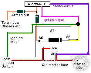
Do you have a 508d in your set-up, turn the shock sensor down and use a 508d, properly set-up it's far more effective any way and cut its black grounding wire via a mini relay from the grey on the 530t.
-------------
Amateurs assume, don't test and have problems; pros test first. I am not a free install service.
Read the installation manual, do a search here or online for your vehicle wiring before posting.
Posted By: cristu
Date Posted: May 18, 2011 at 11:10 AM
You're right, I could turn the shock sensor all way down and use the 508d. And I do wire already an relay to the black wire and grey wire from 530T and it bypasses the motion sensor while I play with the windows. Disabling the shock sensor an the brain involves open it up and cut power or ground from shock sensor ?
Posted By: cristu
Date Posted: May 18, 2011 at 11:11 AM
You're right, I could turn the shock sensor all way down and use the 508d. And I do wire already an relay to the black wire and grey wire from 530T and it bypasses the motion sensor while I play with the windows. Disabling the shock sensor an the brain involves open it up and cut power or ground from shock sensor ?
Posted By: cristu
Date Posted: May 18, 2011 at 11:13 AM
You're right, I could turn the shock sensor all way down and use the 508d. And I do wire already an relay to the black wire and grey wire from 530T and it bypasses the motion sensor while I play with the windows. Disabling the shock sensor an the brain involves open it up and cut power or ground from shock sensor ?
Posted By: howie ll
Date Posted: May 18, 2011 at 12:22 PM
Cut either it doesn't matter black or red on 508d, grey from 530t to 85, constant 12V+ to 86, 508d BLACK/ red to 87a, other cut end to 30.
If you're using a 528t as a delay on, use that! Save you using the extra relay.
-------------
Amateurs assume, don't test and have problems; pros test first. I am not a free install service.
Read the installation manual, do a search here or online for your vehicle wiring before posting.
Posted By: cristu
Date Posted: October 31, 2011 at 4:02 AM
Hello,
I have installed DEI 545 Nite-Lite system to my car and it works good. Also I do not cut the red loop witch can provide me daytime running lights. The problem is when I start the engine the light go on first. I want to delay the light by 5-8 secs after I start the engine.
I put the contact, wait for 3 secs to check the sparks (diesel), start the engine and then the headlights to start. Is any possibility to do this ? by relay or something ? Thanks
Posted By: howie ll
Date Posted: October 31, 2011 at 4:48 AM
Use a 528t as a delay.
-------------
Amateurs assume, don't test and have problems; pros test first. I am not a free install service.
Read the installation manual, do a search here or online for your vehicle wiring before posting.
Posted By: cristu
Date Posted: October 31, 2011 at 5:25 AM
Hi Howie,
Can you tell me how to connect it ?(diagram)
Thanks
Posted By: howie ll
Date Posted: October 31, 2011 at 6:00 AM
Cut blue loop, ignition to BLACK/ white, cut light feed, switch side to orange, lights side to yellow, black to 0v (ground), red to constant 12v+ and brown not used, set timer for X seconds.
-------------
Amateurs assume, don't test and have problems; pros test first. I am not a free install service.
Read the installation manual, do a search here or online for your vehicle wiring before posting.
Posted By: cristu
Date Posted: April 28, 2012 at 5:10 AM
Hi Howie II,
Regarding to my problem with the delay of DEI 545t Daytime running light module.
On the 545t module I have an wire - Yellow (+) ignition input: connect to a switched ignition input. What is this mean with this wire ? Right now the wire is not connect to ignition.
Can this wire solve my problem with the delay, without use an extra 528t relay ?
Thanks
Posted By: howie ll
Date Posted: April 28, 2012 at 12:24 PM
Sorry, haven't a clue.
-------------
Amateurs assume, don't test and have problems; pros test first. I am not a free install service.
Read the installation manual, do a search here or online for your vehicle wiring before posting.
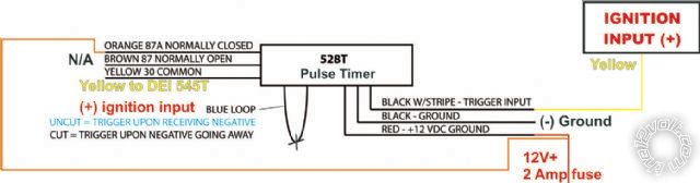
Posted By: cristu
Date Posted: October 08, 2012 at 11:18 AM
Hello Howie,
I finally got the 528t relay to connect my 545t light module.
I want to delay only the (+) ignition input from my starter to the ignition input wire from the 545t module (to start the lights at an amount of preselected timer 0-60 secs).
I attached an draw to see if it's right
Thanks 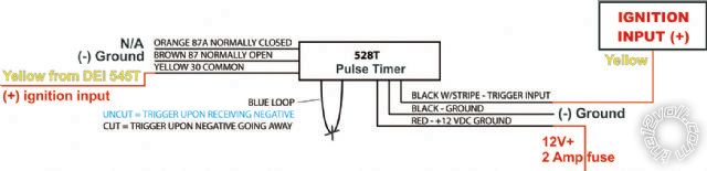
Posted By: howie ll
Date Posted: October 08, 2012 at 11:24 AM
How not to fry your 545t.
Brown goes to the same source as your RED.
Otherwise when it's triggered the 528t will feed brown (NEG) in YOUR diagram to yellow...oops.
-------------
Amateurs assume, don't test and have problems; pros test first. I am not a free install service.
Read the installation manual, do a search here or online for your vehicle wiring before posting.
Posted By: howie ll
Date Posted: October 08, 2012 at 11:25 AM
No still wrong.
Brown not connected, orange to red, everything else stays the same, that will give you a delay on.
-------------
Amateurs assume, don't test and have problems; pros test first. I am not a free install service.
Read the installation manual, do a search here or online for your vehicle wiring before posting.
Posted By: cristu
Date Posted: October 08, 2012 at 12:06 PM
Like this ?
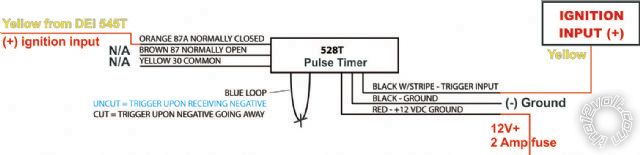
Posted By: howie ll
Date Posted: October 08, 2012 at 4:36 PM
Not at all, like this:- 545t.bmp------------- Amateurs assume, don't test and have problems; pros test first. I am not a free install service.
Read the installation manual, do a search here or online for your vehicle wiring before posting.
Posted By: cristu
Date Posted: October 09, 2012 at 12:11 AM
Ok, thakns
Posted By: cristu
Date Posted: February 25, 2013 at 12:20 PM
Hello everyone,
I want to install an extra module to my alarm Viper 5002 for remote start.
I have decided to Viper 5101 remote start and I need to know what other modules should I add to this comfort module to work. My car is diesel, 2009, by Dacia (renault - eastern europe).
What I've read is that I need an XK05 XpressKit Remote Start Interface or and DB-ALL interface. What should I choose to work properly ?
Can you advice me ? Thank you.
Posted By: howie ll
Date Posted: February 25, 2013 at 2:31 PM
No you don't you already have virtually everything hard wired so just use a 556U as the by-pass.
-------------
Amateurs assume, don't test and have problems; pros test first. I am not a free install service.
Read the installation manual, do a search here or online for your vehicle wiring before posting.
Posted By: cristu
Date Posted: March 05, 2013 at 3:50 AM
I have checked my vehicle's diagram and my ignition switch wiring look like this:
4 wires in diagram:
1. +12V AFTER IGNITION
2. +12V ACCESSORIES FEED
3. PROTECTED +12V BATTERY FEED > PASSENGER COMPARTMENT 3
4. STARTER +12V
How can I connect those to my Viper 5101 ?
Do I need to cut the starter wire and wire the key side to 87A of flex relay and car side to 30 of flex relay together
with violet (H3/4) ? For use as anti-grind relay ?
Heavy gauge remote start, (H3) 8-pin connector
==============================================
H3/1 PINK IGNITION 1 INPUT/OUTPUT >>>> is 1. +12V AFTER IGNITION ??
H3/2 RED / WHITE (+) FUSED (30A) IGNITION 2 / FLEX RELAY INPUT 87 >>>> not used
H3/3 ORANGE ACCESSORY OUTPUT >>>> 2. +12V ACCESSORIES FEED
H3/4 VIOLET STARTER OUTPUT >>>> 4. STARTER +12V/CUT (car side)
H3/5 RED (+) FUSED (30A) IGNITION 1 INPUT >>>> 3. PROTECTED +12V BATTERY FEED > PASSENGER COMPARTMENT 3 ? Or should I take 12V constant from battery
H3/6 PINK/WHITE IGNITION 2 / FLEX RELAY OUTPUT 30 >>>> 4. STARTER +12V/CUT (car side)
H3/7 PINK/BLACK FLEX RELAY INPUT 87A key side (if required) of FLEX RELAY >>>> 4. STARTER +12V/CUT (key side)
H3/8 RED / BLACK (+) FUSED (30A) ACCESSORY/STARTER INPUT >>>> 3. PROTECTED +12V BATTERY FEED > PASSENGER COMPARTMENT 3 ? Or should I take 12V constant from battery
Please correct me if I'm wrong.
Regarding tach wire I have the following diagram from my injection computer:
=================================================================
No mm2 Sym ... > ...
=================================================================
H4 0.75 NH ENGINE EARTH C112
B1 0.5 3JN FAN 1 RELAY - CONTROL CQ0A
C1 0.5 3JP FAN 2 RELAY - CONTROL CQ0A
D1 0.5 AP29 PROTECTED + AFTER IGNITION ENGINE FUNCTION FUSE CQ0A
G1 1.0 3FB INJECTION + > PROTECTIVE RELAY C112
H1 0.75 NH ENGINE EARTH C112
B2 0.5 H7 REV COUNTER > TOP DEAD CENTRE > COIL >COMPUTER ALTERNATOR SIGNAL CQ0A
F2 0.5 3LU + LOAD POTENTIOMETER 2 CQ0A
G2 0.5 3LR + LOAD POTENTIOMETER 1 C112
H2 0.5 3LS LOAD POTENTIOMETER 1 + SIGNAL C112
A3 0.5 133C INSTRUMENT PANEL CAN L SIGNAL > COMPUTER CQ0A
B3 0.5 38LQ FAN ASSEMBLY SPEED 0 SIGNAL CQ0A
E3 0.5 5A BRAKE PEDAL SWITCH + SIGNAL CQ0A
F3 0.5 3LW LOAD POTENTIOMETER 2 + SIGNAL CQ0A
H3 0.5 3LT - LOAD POTENTIOMETER 1 C112
A4 0.5 133B INSTRUMENT PANEL CAN H SIGNAL > COMPUTER CQ0A
B4 0.5 HK DIAGNOSTIC SIGNAL K CQ0A
E4 0.5 65A BRAKE LIGHTS + CONTROL CQ0A
F4 0.5 3LV - LOAD POTENTIOMETER 2 CQ0A
G4 0.75 NH ENGINE EARTH
I think is B2-REV COUNTER > TOP DEAD CENTRE > COIL >COMPUTER ALTERNATOR SIGNAL
Pin 4 Blue from Xpresskit model: TBXKEY (can't find DEI 556U) GWR (from RCS) goes to pin 5 BLUE (-) 200mA STATUS OUTPUT from RCS ?
My car is diesel so I need to connect H2/7 GRAY/BLACK (-) DIESEL WAIT TO START INPUT and can't find him. Can I connect it to the bulb in my dash ?
Thanks
Posted By: cristu
Date Posted: March 06, 2013 at 3:52 AM
Can anyone help me how to wire 5101 module at the ignition harness ?
Posted By: cristu
Date Posted: March 09, 2013 at 7:42 AM
I have one question: If I put my key into bypass module (TBXKEY or 556U), am I protected by thieves ? I know that is a stupid question.
If somenone breaks the car, cut the alarm/remote start power and takes the key from bypass module, can he start the car with the key ? Or how can I make sure that he cannot start or drive the car even he's got the key from the bypass module ? Is there a way to protect starting the car ?
Posted By: howie ll
Date Posted: March 09, 2013 at 10:25 AM
How would the thieves even know there's a key in the box in the car?
-------------
Amateurs assume, don't test and have problems; pros test first. I am not a free install service.
Read the installation manual, do a search here or online for your vehicle wiring before posting.
Posted By: cristu
Date Posted: March 09, 2013 at 9:52 PM
Maybe someone sees the car is starting alone a few times and he 'becames" interesting by stealing it. I want to know if I protect starting the car with the key from bypass. Someone else said to cut the starter wire and wire it through the module as a starter kill, if the power falls out from the RS the he cannot start the engine.
Posted By: howie ll
Date Posted: March 10, 2013 at 3:18 AM
One would have "assumed" that's how you would have done it in the first place.
-------------
Amateurs assume, don't test and have problems; pros test first. I am not a free install service.
Read the installation manual, do a search here or online for your vehicle wiring before posting.
Posted By: cristu
Date Posted: March 10, 2013 at 4:46 AM
Yes, i know that but in my case a keyless bypass cannot be done so i want to use the onboard relays from RS as a kill starter, is it possible or should not do this ? can you please tell me how to wire it up ? Thank you in advance.
Posted By: howie ll
Date Posted: March 10, 2013 at 6:53 AM
That diagram will disable remote start whilst alarm is on this one is better:-
35E_starter_cut.bmp------------- Amateurs assume, don't test and have problems; pros test first. I am not a free install service.
Read the installation manual, do a search here or online for your vehicle wiring before posting.
Posted By: cristu
Date Posted: March 10, 2013 at 7:06 AM
I appreciate your help very much, Thank You.
Posted By: cristu
Date Posted: March 14, 2013 at 5:55 AM
Still not decided what bypass should I use for my RS, I rather prefer a keyless bypass like Xpresskit XK05 with PKTI firmware witch is available for me to buy it from a local store.
The install seller told me that this kind of bypass is compatible with my car and he installed a lot of them for my type of car but he
didn't want to tell me how can I make the connections unless Is installed by them.
So I try to figure out with the installation manual
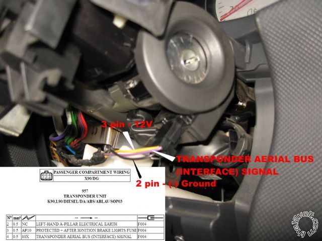
next to ignition barrel witch wires should I connect but I don't see any plugs like T8 Black or E5 White located at the ignition switch
only transponder plug with 3 wires (12V+, antenna signal from Ignition Immobilizer system and (-) ground). The RX/TX wires are missing.
This wire (pin 4 - Transponder aerial bus interface signal) goes to passenger compartment computer (pin A16 - Black) and then from this unit (at pin B36 - Green) a wire goes to injection computer (gray module - B4)
I want to figure out how RX / TX wires are function it for transponder Ignition Immobilizer and how can I wire them to my transponder.
Here's a picture with my ignition barrel.
Posted By: howie ll
Date Posted: March 14, 2013 at 6:20 AM
Pay the installer to do it.
I have no info on Renault.
-------------
Amateurs assume, don't test and have problems; pros test first. I am not a free install service.
Read the installation manual, do a search here or online for your vehicle wiring before posting.
Posted By: cristu
Date Posted: March 14, 2013 at 6:35 AM
I see...I think so.
Posted By: cristu
Date Posted: March 21, 2013 at 12:03 PM
Since I already have an alarm system installed on my car (Viper5002) and installing the RS 5101, I know that I'll carry 2 remotes after me. The main function of the second remote from RS is just remote start. I'm not planning to use the lock/unlock or aux buttons. But If I accidentally press the unlock button what is the consequence ?
What will happen if i press unlock button from the RS remote control, the car is unlocking and disarming ? But If I press lock button from RS when it's unlocked/disarmed, it will lock and arm ?
Or the RS remote will supply functions (lock/unlock/arm/disarm) of alarm remote ?
I'm asking you because there are some common connections from viper 5002 and 5101 RS module regarding the lock/unlock doors.
Should I use diodes when the wires from RS and alarm meets at the plug ?
Common wires from RS and security alarm (Viper 5002):
H1/8 GREEN(-) DOOR TRIGGER INPUT
H1/11 WHITE PARKING LIGHT OUTPUT
Pin 1 BLUE (+) LOCK (-) UNLOCK OUTPUT
Pin 3 GREEN (-) LOCK (+) UNLOCK OUTPUT
And I already have a hood pin connected at 5002. I know that GRAY(-) HOOD PIN SWITCH INPUT from RS is required to be connected in MTS mode. Can I connect this wire together with the hood pin wire from the alarm ? Should I use diodes ?
Posted By: howie ll
Date Posted: March 21, 2013 at 4:45 PM
Use the WHITE/ blue aux output connect to the WHITE/ blue on your R/S then you can use the alarm's remote. Read the instructions.
-------------
Amateurs assume, don't test and have problems; pros test first. I am not a free install service.
Read the installation manual, do a search here or online for your vehicle wiring before posting.
Posted By: cristu
Date Posted: March 22, 2013 at 1:38 AM
That's great. I didn't know that H1/10 WHITE/ BLUE 200 mA (-) channel 3 output from my alarm can do that. Right now it's allocated to DEI 530T windows system so I will move it to another aux channel.
Right how this channel is on default setting 'Validity', should I program to 'latched/latched, reset with ignition/30-second/60-second/90-second timed/remote start report' ?
Channel 3:
3-5 Channel 3: Validity(default), latched/latched, reset with ignition/30-second/60-second/90-second timed/remote start report
3-6 Channel 3: Linking (none)(default), Arm, Disarm, both
Regarding the common wires from the RS and alarm, is there a problem if I put them together ?
Thanks
Posted By: howie ll
Date Posted: March 22, 2013 at 2:01 AM
Leave it in validity.
No, but if those common wires aren't required by the R/S, don't install.
-------------
Amateurs assume, don't test and have problems; pros test first. I am not a free install service.
Read the installation manual, do a search here or online for your vehicle wiring before posting.
Posted By: cristu
Date Posted: April 17, 2013 at 12:05 PM
Hi, I have successfully installed my RS (viper 5101) and it works ok. I still have an inconvenient regarding the integration with my security system (Viper 5002)
When I start the car by remote (5101s remote) the alarm from viper 5002 is triggering and it blows up the siren.
How can I start the car without triggering the alarm ?
The steps which I make:
MTS ok.
Leave the car, lock the doors with 5101 remote, the engine shuts off.
Arm the car with 5002s remote (for alarm)
To start the car remote:
Disarm/unlock the car with 5002s remote (If I start armed, its triggering)
Remote start the car with 5101 remote
The car starts but cannot arm again with the 5002s remote. If the engine is running the 5002s remote DOES NOT respond to any command.
If I connect the H1/10 WHITE/ BLUE 200 mA (-) channel 3 from viper 5002 to H1/10 WHITE/ BLUE (-) REMOTE START/ TURBO TIMER ACTIVATION INPUT from 5101 the car starts using the AUX 3 from 5002 remots but cannot arm using viper 5002s remote. The viper 5002s remote does not respond to any command.
Its very annoying for me this thing. The main problem is that I cannot use my security remote to manage the RS, especially the triggering thing.
Thanks.
Posted By: cristu
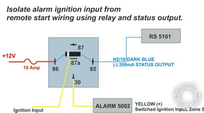
Date Posted: April 17, 2013 at 1:48 PM
Can I use the H2/10 Dark Blue from RS (-) 200mA STATUS OUTPUT connected to the hood pin wire of the alarm brain ? As long as the alarm sees the hood as open, it will continue to ignore the shock sensor ?
Right now at the hood pin are connected the wire from alarm and the one from RS - GRAY N/O or N/C (-) HOOD PIN SWITCH INPUT. Just an thought.
I just need to bypass alarm while remote start.
Posted By: howie ll
Date Posted: April 17, 2013 at 5:24 PM
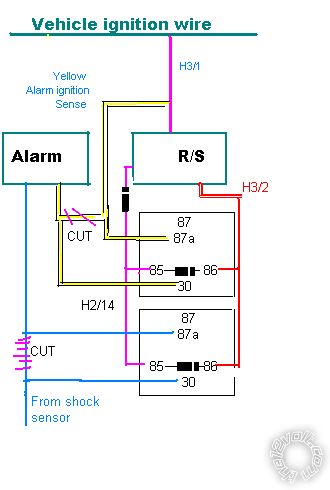
Just do this, in fact initially just do the shock sensor wire and see what happens.
The 3 x 1N4004 diodes are absolutely mandatory.
stop_alarm.bmp------------- Amateurs assume, don't test and have problems; pros test first. I am not a free install service.
Read the installation manual, do a search here or online for your vehicle wiring before posting.
Posted By: cristu
Date Posted: April 17, 2013 at 9:19 PM
Hi Howie, I have the shock sensor built in the alarm's brain.
Posted By: howie ll
Date Posted: April 18, 2013 at 1:58 AM
Sorry, this thread is becoming a bit much, you mentioned instant trigger and I was confused.
The basic problem is that you need to throw away or sell on your separate units and buy a combo such as 5202, 5204.
-------------
Amateurs assume, don't test and have problems; pros test first. I am not a free install service.
Read the installation manual, do a search here or online for your vehicle wiring before posting.
Posted By: howie ll
Date Posted: April 18, 2013 at 2:00 AM
One more thought, is there a second ignition on this vehicle?
-------------
Amateurs assume, don't test and have problems; pros test first. I am not a free install service.
Read the installation manual, do a search here or online for your vehicle wiring before posting.
Posted By: cristu
Date Posted: April 18, 2013 at 2:57 AM
I cannot sell or throw away the module, I just bought it, at least not now.
At the ignition switch I have 4 wires which I connected to RS:
- 12v+ constant (RED)
- Ignition (Yellow)
- Acc (GREEN/ YELLOW)
- Starter (Orange)
What about second ignition wire ?
Posted By: howie ll
Date Posted: April 18, 2013 at 3:02 AM
Try that isolating trick on the second ignition, that's how it works on Peugeots, might be worth a chance.
-------------
Amateurs assume, don't test and have problems; pros test first. I am not a free install service.
Read the installation manual, do a search here or online for your vehicle wiring before posting.
Posted By: cristu
Date Posted: April 18, 2013 at 3:10 AM
I don't understand, how can I isolate ?
Posted By: cristu
Date Posted: April 18, 2013 at 6:13 AM
O, I think I know what you mean: Isolate alarm ignition input from remote start wiring using relay and status output ?
Can I use BLUE (-) 200mA STATUS OUTPUT or PINK (-) 200mA IGNITION 1 OUTPUT with a relay connected at alarm ignition input ?
How can I wire the relay ? Thanks Howie and sorry for bothering you.
Posted By: howie ll
Date Posted: April 18, 2013 at 8:09 AM
Sorry but you'll have to refer to DEI in Romania, that's their European R & D centre, I just don't have the time.
-------------
Amateurs assume, don't test and have problems; pros test first. I am not a free install service.
Read the installation manual, do a search here or online for your vehicle wiring before posting.
Posted By: howie ll
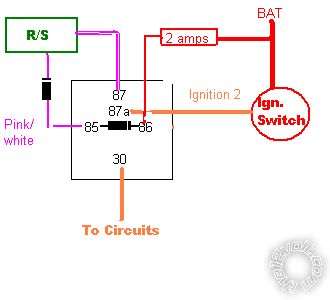
Date Posted: April 18, 2013 at 8:27 AM
Try this and if it doesn't work, repeat with ignition 1 as well.
You still won't disable the shock sensor.
isolate_ignition.bmp------------- Amateurs assume, don't test and have problems; pros test first. I am not a free install service.
Read the installation manual, do a search here or online for your vehicle wiring before posting.
Posted By: cristu
Date Posted: April 19, 2013 at 1:29 AM
I have made 2 relay diagrams after your suggestion regarding Ignition 2 or Ignition 1 wires.
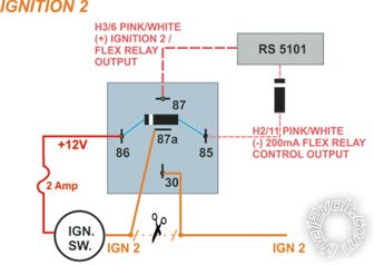
and
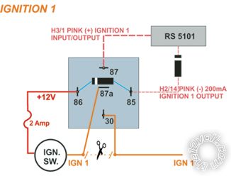
Is this correct ?
On the other hand I found some DIY Troubleshooting from Directed and at page.11 says to isolate ignition input from alarm to prevent trigger while remote started using status output.
[URL=https://www.drdetailshop.com/DIY_Troubleshooting.pdf]DIY Troubleshooting[/URL
Is this schematic ok ? It's more convenient for me.
Thanks
Posted By: howie ll
Date Posted: April 19, 2013 at 1:32 AM
The lowest diagram is exactly the upper one I showed you the other day, it was my first suggestion.
Except you've drawn it better.
-------------
Amateurs assume, don't test and have problems; pros test first. I am not a free install service.
Read the installation manual, do a search here or online for your vehicle wiring before posting.
Posted By: cristu
Date Posted: April 19, 2013 at 1:41 AM
All right I'll try this today and let you know.
Posted By: cristu
Date Posted: April 19, 2013 at 7:55 AM
Well, it looks like the last diadram it's ok for me. Does not trigger the alarm any more.
I have adjusted the sensibility of the shock sensor a little bit lower for warns comming from alarm with ignition on (shaking of diesel engine).
Overall I'm satisfied, we'll see in time the behavior of it.
Anyway, Thank You Howie, again. Cheers
|