viper 3303 and door lock problem
Printed From: the12volt.com
Forum Name: Car Security and Convenience
Forum Discription: Car Alarms, Keyless Entries, Remote Starters, Immobilizer Bypasses, Sensors, Door Locks, Window Modules, Heated Mirrors, Heated Seats, etc.
URL: https://www.the12volt.com/installbay/forum_posts.asp?tid=127243
Printed Date: March 14, 2026 at 9:53 AM
Topic: viper 3303 and door lock problem
Posted By: deoz
Subject: viper 3303 and door lock problem
Date Posted: May 06, 2011 at 10:09 AM
Guess I missed the part about paste from word. here is the post again:
First off forgive my rambling if this post drones on, please bare with me. Doing lots of research and this topic seems to be beaten to death but I would greatly appreciate help.
Basic information:
Car: 1991 Ford Mustang GT with power door locks
Alarm: Viper 2-Way 3303 has internal relays for the door locks as well as a flex relay for additional I/Os
First off Not pleased that the only instructions that come with this alarm are the user instructions for the remote and a pin-out diagram. So your left with your best judgment for most of the connections. This is not a problem for the basic stuff (trunk pop, parking lights, door open input, etc).
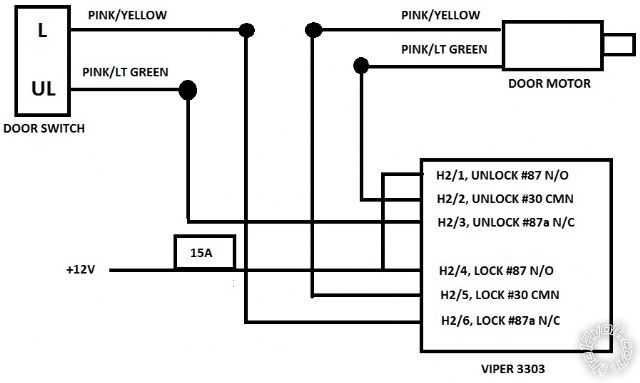
I am having a problem with this reverse polarity door lock system and the internal relay door lock wiring that the 3303 comes with. I was sure I had installed this correctly but I guess I was wrong. Attached is a quick wiring diagram as to how I have it hooked up.
So when just one action is connected, either lock or unlock, the doors seem to only want to lock no matter how I have it connected. But with both actions, lock and unlock connected simultaneously the fuse pops for the alarms relay power. The internal relay only allows you access to pins 37, 37a, and 30. I am assuming (due to the lack of instructions or further detail of how their internal relay works from Viper) that pin 35 is being used by the circuit board to activate the relay (alarm out -) but I have no idea as to what theyre doing with pin 86 inside that box. Should I wire up separate outside relays and find a way to get the 3303 to output a (-) so it activates the door locks like a normal alarm and forget about using the internal relays?
Any help would be appreciated.
Replies:
Posted By: deoz
Date Posted: May 06, 2011 at 12:04 PM
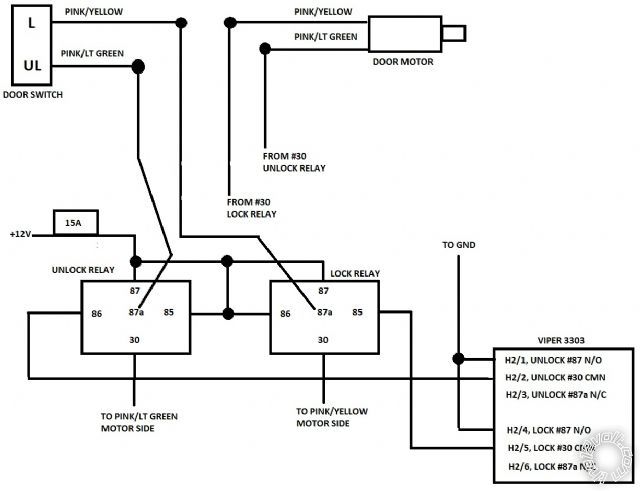
Seems like a complete waste of the "internal" relays for the 3303 but would this work? I hope new cars can take advantage of the 3303's internal relays, cause if everyone still needs to wire up external ones seems like a joke to me.
Posted By: howie ll
Date Posted: May 06, 2011 at 5:48 PM
Your wiring is correct, please test the lock outputs from the 3303.
-------------
Amateurs assume, don't test and have problems; pros test first. I am not a free install service.
Read the installation manual, do a search here or online for your vehicle wiring before posting.
Posted By: deoz
Date Posted: May 06, 2011 at 7:40 PM
I have it wired up exactly like the second picture it only wants to lock not unlock and Not blows the power fuse when I try to Um lock it
Posted By: deoz
Date Posted: May 06, 2011 at 7:55 PM
So just to expand both lock and unlock are sending a ground signal from the 3303. Wired up like diagram #2 unlock button locks the doors lock button does nothing. If I try to flip flop any wires I blow fuses.
Posted By: deoz
Date Posted: May 06, 2011 at 8:43 PM
Mental note 91 mustangs two pink with yellow wires and pink/LT grn = lock and pink / YELLOW = unlock Not sure why my car is backwards
Posted By: howie ll
Date Posted: May 07, 2011 at 3:50 AM
Don't be angry but the fuse blow symptom on tells me you've either actually wired it wrong in the first place or something is the "wrong way round".
-------------
Amateurs assume, don't test and have problems; pros test first. I am not a free install service.
Read the installation manual, do a search here or online for your vehicle wiring before posting.
Posted By: deoz
Date Posted: May 07, 2011 at 4:25 PM
it's ok not mad at all. Come to find out I had two pink with yellow wires in that harness at the kick panel. Who knew :) I got everything sorted out all though I did find the lock/unlock wires to be backwards to what all the wiring diagrams for the 90-93 guides said.
Posted By: howie ll
Date Posted: May 07, 2011 at 4:34 PM
Glad you sorted it, the other wire must have been sitting on ground to blow the fuse.
-------------
Amateurs assume, don't test and have problems; pros test first. I am not a free install service.
Read the installation manual, do a search here or online for your vehicle wiring before posting.
Posted By: mkraffert
Date Posted: May 15, 2011 at 8:01 PM
OK, this looks like what I need to do in my 1998 Expedition, but I'm not sure. I have a Python 700 2-way system. I've installed the system and all the "alarm" functionality works fine. The problem I am having is with the door locks and the dome light supervision. The system has build in relays, and LOUSY instructions. The system has the following wires:
H3/A - Domelight Supervision Relay Input #87 - BLACK/ White
H3/B - Lock #87a Normally Closed - WHITE/ Black
H3/C - Lock #30 Common (Output) - GREEN/ Black
H3/D - Lock #87 Normally Open (Input) - Violet/Black
H3/E - Unlock #87a Normally Closed - BROWN / Black
H3/F - Unlock #30 Common (Output) - Blue/Black
H3/G - Unlock #87 Normally Open (Input) - Violet* (Common with H3/D at fuse holder)
and
H1/9 - Domelight Supervision Relay Output #30 - This wire is ALSO BLACK/ White and has a note in the manual that reads: If the input wire H3/A is not connected there will be no output on this wire.
I have identified the following wires in the wiring diagram and have found them in the vehicle:
Power Lock - Pink / YELLOW
Power Unlock - Pink/Green
Lock Motor - Pink/Black
Domelight Supervision - Polarity Positive - BLACK/ Light Blue
The instructions assume I know how to properly connect these wires based on the descriptions, but I don't, and I don't want to connect them wrong and fry the brain or anything. Can someone please point me to a diagram or describe the correct connections for this?
Thanks!
Mark Kraffert
Posted By: deoz
Date Posted: May 15, 2011 at 11:11 PM
Well the hits keep on coming. With all the overtime I have been doing at work I have not had time to finish the install once I finished figuring out the door lock problem. I had time this Sunday to finish her up and now I seem to be having a problem with the starter disable feature.
So again no instructions just a pin out diagram. The harness for the starter kill is 3-wires and what I was assuming connected to an internal relay inside the alarm brain.
pin 1, GREEN / WHITE: Starter - common (key side) [I assume this is pin 30 on the relay]
pin 2, Green: Starter - Normally Open (motor side) [I assume this is pin 87 on the relay]
pin 3, GREEN/ Black: Starter - Normally Closed (motor side) [I assume this is pin 87a on the relay]
This these assumptions I was guessing I would cut the starter wire insert the key side to pin 1 and the starter side to pin 2 so when the alarm is on/active the starter circuit would be not active but when the alarm was off the relay would activate allowing the circuit to complete and start the car. Well come to find out regardless if the alarm is active, on, off, etc. it will not pass signal through these two pins no matter what I do.
So thinking the internal relay activates the other way around I changed the connections to pins 1 and 3. Now the car starts BUT it starts all the time, even if the alarm is going off horns blaring!
So what am I doing wrong? I am starting to feel pretty owned by this darn thing I have installed other alarms including a remote starter clifford G5 system in a 350z, but good lord this one is just kicking my butt. All the other alarms I have used just had two wires for the starter kill system. One for the key side one for the motor side, is there just something I am missing with this 3-wire system?
Again back to work next week so the car will sit but any help would be greatly appreciated.
Posted By: mkraffert
Date Posted: May 15, 2011 at 11:19 PM
On my system, you only use 2 of the 3 wires. You cut the starter wire from the key. The GREEN / WHITE wire goes to the key side wire and the GREEN/ black or green goes to the other side, depending on your vehicle. I used the GREEN/ black on my Ford.
Posted By: deoz
Date Posted: May 15, 2011 at 11:26 PM
Was this on a 3303? I can start the car as well on that configuration but I can still start the car when the alarm activates this kind of undermines the idea of having it.
Posted By: mkraffert
Date Posted: May 15, 2011 at 11:34 PM
It's a Python 700, which is the same as a 3201. On mine, when the alarm is armed, if I try to start the car, it trips the alarm and the starter won't crank.
Posted By: deoz
Date Posted: May 15, 2011 at 11:44 PM
Bummer well this 3303 seems to be the odd duck of vipers line up, and I seem to be the only one with it hehe. Any other suggestions?
At this point I could "rig it" for a lack of better words. The alarm has a ground output then active I could wire in an external relay that will cut the starter circuit when active but then when the alarm is off it will do the reverse. It seems to be a shame that I would have to do this instead of using the part that is built into the brain.
Posted By: mkraffert
Date Posted: May 15, 2011 at 11:49 PM
The Python is made by Viper. Mine has the relay built into it internally. I think what I described will work for yours too. Even the color codes on the wires are the same between the 2 systems.
Posted By: howie ll
Date Posted: May 16, 2011 at 2:38 AM
Deoz do you have a yellow ignition input wire on the 3303?
If so please use it then wire the starter cut as NC
Re your assumptions.
Wrong!
GREEN / WHITE key side =87a.
-------------
Amateurs assume, don't test and have problems; pros test first. I am not a free install service.
Read the installation manual, do a search here or online for your vehicle wiring before posting.
Posted By: deoz
Date Posted: May 16, 2011 at 10:49 AM
Yes I have the yellow 12v Sweet wire and with it hooked up or not it reacts the same as explained above.
|