’11 toyota camry rs cranks no start
Printed From: the12volt.com
Forum Name: Car Security and Convenience
Forum Discription: Car Alarms, Keyless Entries, Remote Starters, Immobilizer Bypasses, Sensors, Door Locks, Window Modules, Heated Mirrors, Heated Seats, etc.
URL: https://www.the12volt.com/installbay/forum_posts.asp?tid=127733
Printed Date: May 13, 2026 at 12:06 PM
Topic: ’11 toyota camry rs cranks no start
Posted By: gamez1515
Subject: ’11 toyota camry rs cranks no start
Date Posted: June 24, 2011 at 6:49 PM
Installed Viper 5901 with Idatalink ads-al(TB)-tl2 on Camry 2011 "G" Stamped key
2011 Camry Std.key 80-bit Sedan Automatic 4 Cyl with no push to start
When I press remote start the starter begins to crank but no start. As soon as I put in the key (without turning it to on) the car starts.
5901
H2/10 Dark Blue to Blue wire at ignition Camry
ADS
GWR Blue/White to Blue wire at ignition Camry
I did not use the diode that is listed in the diagram because i have read in another post that it is not needed. Could this be my problem?
Another question I have is for the door locks. I found the blue and green wire but I'm not getting a negative reading. I have connected them directly to the 5901 and they do not lock or unlock.
Thanks in advance.
Replies:
Posted By: kreg357
Date Posted: June 24, 2011 at 8:06 PM
The diode is to prevent the Keysense signal, created when the key is in the ignition switch, from turning on the
bypass module. I would install a diode or, in the case of a Viper 5901, if you are not using the H2/16 Blue/White
wire for the defrost function, you could use it as a second (-) Status Output. ( H2/10 for the bypass & H2/16 for Keysense.)
A few question about the bypass. Assuming you are running in W2W mode from the (-) Status / GWR wiring.
Is it downloaded / flashed with the ADS AL(TB)-TL2 firmware?
Did you set its' mode to "Standard", two blinks? Top of Page 34
Did the bypass program as per the instructions in the install guide? Bottom of Page 34
On the door locks :
Here is info from DEI. Did you test by using the passenger switch?
Power Lock blue (test with passenger switch) - dash fuse box, white 12 pin plug (J), pin 3
Power Unlock green (test with passenger switch) - dash fuse box, white 12 pin plug (J), pin 4 ------------- Soldering is fun!
Posted By: gamez1515
Date Posted: June 24, 2011 at 8:26 PM
Thanks for your quick response
So the H2/16 goes to blue wire at ignition along with blue/white from ADS? Where does H2/10 get connected?
It is flashed with the ADS AL(TB)-TL2 firmware
I haven't set it's mode to standard or bypassed but will do that now. And I will look for the passenger switch. Thanks again will update soon
Posted By: kreg357
Date Posted: June 24, 2011 at 8:58 PM
The Viper has two (-) Status Output wires, H2/10 and H2/16. You can connect H2/10 directly to the ADS (-) Blue/White GWR
input wire. ( Also connect the dashed Power and Ground wires for W2W. Follow the Type 2 Install diagram. )
Verify that the Viper programming for Menu 3, Item 11 is set at the factory default of Opt 1 (-) Status and
connect that to the Camrys' Blue Keysense wire. ------------- Soldering is fun!
Posted By: thecoolmankyle7
Date Posted: June 24, 2011 at 9:11 PM
The Diod is not going to stop in from cranking, I probably would use it but it should still start. The fact that it will remote start with the key in the switch means that it is not bypassing the security. I would try going through the programming process and key learning again. also double check all of your connections including the security light from the bypass mod, it does matter.
Posted By: gamez1515
Date Posted: June 24, 2011 at 9:56 PM
I connected h/10 to ads blue/ white ( by themselves) H16 to keysense blue and now it still cranks without key and as soon as i put key in it turns on but now it turns off after 3 seconds.
After i flash the module what exactly do i do. Ive been reading for a week now guys go easy on me and thanks for the help
Got the power locks to work thanks.
Kyle... Funny you mentioned security light i could not find it in any diagram so i did not connect it. If you can help thanks
Posted By: thecoolmankyle7
Date Posted: June 24, 2011 at 10:16 PM
In that car I thinks its up high on the dash. if you set in the car with the doors shut and lock it with the factory remote it should start flashing. you actualy have to tap it at the light. Did you follow the programming chage that kreg357 mentioned when you use that wire? Me personaly I would have just put the diode in insted,
Posted By: gamez1515
Date Posted: June 24, 2011 at 10:26 PM
I did use that programing change... I wanted to do it without diode. I have to drive 20 miles just to get one. Pick one up tomorrow. I know the security light flashes just hoping i could find it at the fuse box with a certain wire color. Thanks again Kyle
Posted By: kreg357
Date Posted: June 24, 2011 at 10:26 PM
Did you connect the iDatalink bypass to the car as per the Type 2 wiring diagram? Did you program the iDatalink bypass module to the car as per the instructions on Page 34 of the Install Guide?
Did you connect the Viper Tach Input wire, H2/9, to the Camrys' Tach source? Did you program the Viper for Tach Mode? ( Menu 3, Item 2, Option 4 )
Did you do a Tach Learn process on the Viper? ------------- Soldering is fun!
Posted By: gamez1515
Date Posted: June 24, 2011 at 10:39 PM
1. Yes
2. After i flashed the module i connect it with all wiring... With car off i push and release programming button nothing happens.
3. H2/9 connected
4. Yes
5. Yes
Posted By: thecoolmankyle7
Date Posted: June 24, 2011 at 10:45 PM
The learn tach process cant be the problem if it was it would over start or cut off after starting or not start long enought. But the car turning over and over and over but never cranking, then with the factory key setting in the switch with in the lock position lets it crank, means that the security system is not bypassing.
Posted By: kreg357
Date Posted: June 24, 2011 at 11:05 PM
Sounds like the bypass is not programmed to the car yet.
Do a bypass module reset first. Then set Standard mode and program to car as follows.
1. Unplug all the harness to the iDatalink module except the black 4 Pin harness.
2. Unplug the black 4 Pin harness.
3. Press and hold the Programming Button.
4. Plug in the black 4 Pin harness ( while keeping the button pressed).
5. When the LED flashes red, release the Programming Button. The LED will go solid Red for 2 seconds.
6. After a few seconds the LED should start doing a single Green blink. Press the Programming Button once.
7. The LED should start doing a double Green blink. Press and hold the Programming Button until the LED goes solid
green then release the Programming Button.
8. Plug in all the bypasses harnesses.
9. Insert key into ignition.
10. Turn key to START and verify the LED turns solid green for 2 seconds.
11. Turn key to OFF
Try a remote start. ------------- Soldering is fun!
Posted By: gamez1515
Date Posted: June 24, 2011 at 11:44 PM
I reset the programming and it is blinking red. I know for sure I've got the right firmware on the module. Thanks
Posted By: gamez1515
Date Posted: June 24, 2011 at 11:53 PM
With the key in the on position (engine off) and the blinking red light from module i do a remote start and it starts. I turn the key to off and take it out and the car stays on. The light on the module is now flashing green. I don't know if this helps.
Thanks again.
Posted By: kreg357
Date Posted: June 25, 2011 at 4:12 AM
Did you try doing the 11 steps as posted above? Does it successfully complete the 11 steps as posted? If not, at which step does it fail?
A Flashing RED LED with Ignition OFF means "Incorrectly programmed or connected." Verify your wiring and connections. ------------- Soldering is fun!
Posted By: gamez1515
Date Posted: June 25, 2011 at 7:48 AM
It fails at step 10... It flashes red.
Everything is connected correctly as the diagram shows and programmed for that car... except the diode to the keysense or the security light.
I've read somewhere that the imo and imi need to be connected to ecm side. I found the wires behind the glovebox but imi guessing there are two sides to it. i connected it to front side (easy side). Can you explain that for me?
Thanks for all your help guys ;)
Posted By: Mike M2
Date Posted: June 25, 2011 at 8:12 AM
Getting the IMI and IMO behind the glovebox is fine. You can get them right on the front of the plug right where you see them after removing the glovebox. If the cut IMI wire is connected backwards(which can happen) The module will still program correctly and the car will still start, but stall after a few seconds of running(so this isn't your problem). I might add to Kregs instructions above that on step 10 you need to hold it on start for a few seconds sometimes before it turns green. If your light starts flashing before you even get that far the bottom line is you have something wired incorrectly in reguards to the IMI and IMO wires.
The diode for keyesnse will not be needed as long as the blue/white from the Idatalink is the ONLY wire connected to the blue on the RS. The security light wire is not needed to program or make this work in any way. It is only to stop the light from flashing after it remote starts. ------------- Mike M2
Tech Manager
CS Dealer Services
Posted By: kreg357
Date Posted: June 25, 2011 at 8:20 AM
x2 with Mike M2.
Here is a Tech Note from iDatalink. https://12voltdata.com/viewtopic.php?f=243&t=2990
They suggest moving the Gray/Red wire from the ADS module to the other side ( vehicle side ) of the cut yellow wire. That seems to jive with this diagram from Fortin for installation of their EVO-ALL on a new Camry. Fortin also has a nice picture of the connector. https://ifar.ca/en/download/2702/preview.html All these connections are critical and should be soldered. ------------- Soldering is fun!
Posted By: gamez1515
Date Posted: June 25, 2011 at 8:42 AM
I think we just found the problem. I didn't cut the yellow wire... I spliced into it and I didn't connect the WHITE/ Red thinking it wasn't needed because the diagram shows it cut. I feel so stupid right now. Sorry guys. Going to fix this now.
Will update soon.
Posted By: gamez1515
Date Posted: June 25, 2011 at 9:43 AM
No good :(
Grey/Red with WHITE/ Red to vehicle side yellow wire
WHITE/ Black to connector side yellow wire... Flashing red light at start up
should i try WHITE/ red to connector side?
Thanks for your patience and help guys.
Posted By: gamez1515
Date Posted: June 25, 2011 at 10:03 AM
I just went through the programming again with the wires hooked up as diagram shows and i get the solid green light when i switch the key to on, but now when i crank it, it turns on then back off within a second. I also do a remote start now without the key and starts but also turns back off.
It seems like were getting there. Thanks
Posted By: kreg357
Date Posted: June 25, 2011 at 10:55 AM
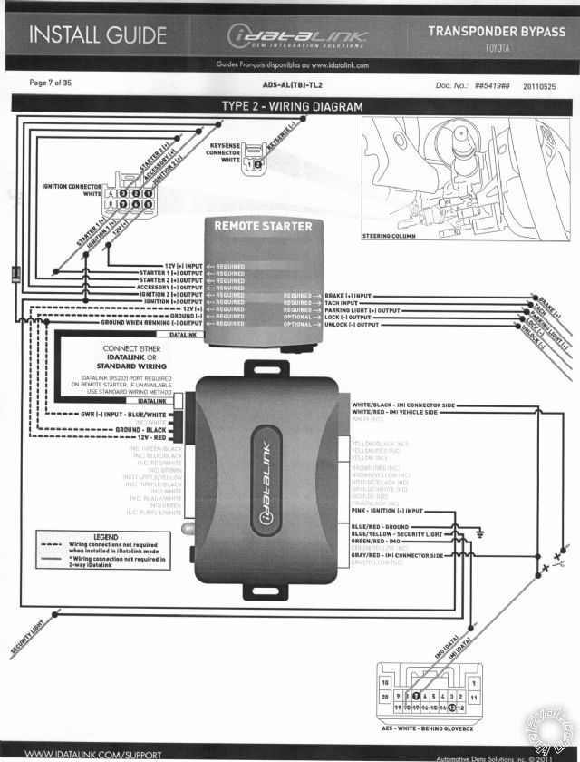
Switch the ADS bypass connections around on the cut Yellow wire. Follow the Type 2 diagram on Page 7 of the install guide. Looks like it is programmed now but if it doesn't work after you switch the wires, you might have to do the 11 Steps again. ( With an iDatalink bypass module you can do a Factory Reset and re-program as many times as it takes.)
-------------
Soldering is fun!
Posted By: Mike M2
Date Posted: June 25, 2011 at 11:55 AM
Yep, he's there just gotta get the correct side of the IMI wires...
-------------
Mike M2
Tech Manager
CS Dealer Services
Posted By: gamez1515
Date Posted: June 25, 2011 at 1:51 PM
Switched the wires car won't start with key or RS. switched back. Car will start wit key. Car will remote start with key in ignition. Car will remote start without key but turns off immediately.
Every time i switch wires or i do something different i program the module. Should i flash the module as well? How do i factory reset module?
Also Im trying to get into viper menu 3 feature 2 option but won't let me... I turn on ignition or turn on car ( tried it both ways) turn it off, press and hold valet. .. Nothing happens
thanks again
Posted By: Mike M2
Date Posted: June 25, 2011 at 2:12 PM
If the IMI wires are backwards the car will start for 4 seconds and shut off. To switch the wires you simply change sides so that what was connected to the plug side is now connected to the harness side, and the same with the other side. The module is programmmed correctly if the light is green and should flash twice while the RS is on. You do not need to reprogram the module when switching the wires.
It may be possible that you have the correct install on the Idata module and it is shutting back off for a different reason. What about a tach wire? Have you programmed that? It is a black wire on the OBD2 connector. It sits off to the right side of the plug by itself... ------------- Mike M2
Tech Manager
CS Dealer Services
Posted By: gamez1515
Date Posted: June 25, 2011 at 2:27 PM
I switched both the imi with the imo still no luck. I tried to program the tach but now it won't let me.
Posted By: kreg357
Date Posted: June 25, 2011 at 3:22 PM
Might be best to start fresh. Verify all the bypass wiring is exactly as per the Type 2 diagram. Make sure all
connections are soldered and insulated. Use the ADS USB cable to re-flash the bypass module with the TL2 firmware.
Then do the 11 Step reset, mode select & set and programming process. Ensure it gives the correct responses at
Steps 5,6,7 & 10.
Steps 1 thru 5 do the Factory Reset.
Steps 6 & 7 do the Mode selection ( iDatalink D2D or W2W ).
Steps 9 thru 11 do the actual programming to the vehicle ( transponder bypass function ).
Tach Programming is strictly a remote starter ( Viper ) function. The bypass has nothing to do with that. Double
check your Tach connection. The easiest place is the Black wire at Pin 9 of the OBD2 connector. Verify the Tach
signal with a Digital Multi Meter. Should be an A/C signal between 0.6V an 5V.
------------- Soldering is fun!
Posted By: gamez1515
Date Posted: June 25, 2011 at 4:15 PM
As I was about to flash my module one more time, I noticed to the right that there is a drop down menu " Select A Protocol"
In the menu:
Idatalink 2-way
Hardwired
DBI
Idatalink 1-way
RF-DBI
Hadn't noticed before... would this make a difference if I chose "Hardwired"
Choosing this changes the firmware from ADS-AL(TB)-TL2(10650) to DBI-AL(TB)-TL2(10670)
Should I try "Hardwired" Or any other?
And Kreg yes everything is soldered and I have done the steps 1 thru 11 many times but when I get to the part where I put in the key to turn it on the red light comes on solid (which means gathering info from vehicle) then turns off then starts blinking red.
Thanks
Posted By: Mike M2
Date Posted: June 25, 2011 at 5:14 PM
gamez1515 wrote:
I switched both the imi with the imo still no luck. I tried to program the tach but now it won't let me.
Ok, you aren't following our instructions if you did this. NEVER change the IMO wire, it is ALWAYS correct. Read my post above. It says to switch the IMI wire ONLY.... ------------- Mike M2
Tech Manager
CS Dealer Services
Posted By: Mike M2
Date Posted: June 25, 2011 at 5:16 PM
Also, If you didn't notice the drop down then it is in DBI. That will work fine for a hard wired module...
-------------
Mike M2
Tech Manager
CS Dealer Services
Posted By: gamez1515
Date Posted: June 25, 2011 at 5:25 PM
There are 3 IMI wires
WHITE/ Black to Connector side
WHITE/ Red to Vehicle Side
Grey/Red To Connector Side
Which goes to which?
Thanks again for your patience.
I am writing down every wire from 5901 unit and ADS module to car... will post soon.
Posted By: kreg357
Date Posted: June 25, 2011 at 6:30 PM
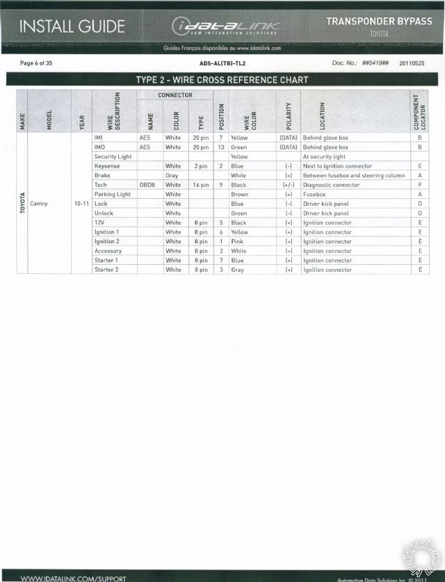
Your Camry has only one IMI wire that you will be connecting to. It is the Yellow wire at Pin 7 of the White
connector behind the cars glove box. The bypass module has 3 wires that will soldered to the cut ends of that
IMI wire, as follows :
ADS AL-CA bypass Camry
WHITE/ Black \___ Both wires to connector Side >
Gray/Red / > of cut Yellow IMI wire.
WHITE/ Red -- Vehicle side of cut Yellow IMI wire - Pin 7 in White connector behind glove box.
GREEN/ Red -- Green IMO wire, Pin 13 same connector. ------------- Soldering is fun!
Posted By: gamez1515
Date Posted: June 25, 2011 at 7:59 PM
H1
H1/2 Red To Black 12V
H1/3 Brown to Siren
H1/5 Black to Ground
H1/8 Green to Brown door Trigger
H1/11 White to Brown Parking Lights
H2
H2/9 Violet/White to Black pin 9 Tach
H2/10 Dk Blue to Blue Keysense
H2/13 Purple to 85 Relay
H2/15 Grey To Hood pin
H2/17 Brown to White B ???
H2/18 BLACK/ White To Ground
H3
H3/1 Pink to yellow Ign.1
H3/2 RED / White to Black 12V
H3/3 Orange to White Accesory
H3/4 Violet to Blue Ign. Car Side
H3/5 Green to Blue Key Side
H3/6 Red to Black 12V
H3/7 Pink/White to Pink Ign.2
H3/9 RED / Black to Black 12V
ADS
GWR Blue/White to Keysense
Ground Black to Ground
12V Red to 12V
PURPLE / White to Pin 9 Black OBD
WHITE/ Black to IMI Yellow Connector Side
WHITE/ Red to IMI yellow Car Side
Pink to Yellow Ign. 1
Blue/Red to Ground
Blue / YELLOW to Security Light not connected
GREEN/ Red to IMO green Pin 13
Grey/Red to IMI yellow Connector Side
Relay 87 and 86 to 12V
Relay 30 to Grey Starter2
Relay 85 to H2/13 Purple
Blue Lock to Green
Green Lock to Blue
Posted By: gamez1515
Date Posted: June 25, 2011 at 8:13 PM
Only 2 wires get cut and thats the Blue for ignition and the yellow for the IMI right?
Everything else gets spliced.
Posted By: kreg357
Date Posted: June 25, 2011 at 8:27 PM
Yes, only two wires to cut and the Blue Starter1 wire is optional if you want Starter Kill / Anti-Grind.
Suggestions:
1.) H2/10 to ADS GWR Blue/White only. Get a diode or use H2/16 for Keysense. Verify Menu 3 Item 11 programming.
2.) ADS PURPLE / White - not used - disconnect
3.) Add fuse to Relay 86 & 87 to +12v
4.) H1/11 verify internal Fuse/Jumper set to (-) :: PARKING LIGHTS ( - ) BLACK (-) @ HEADLIGHT SWITCH, WHITE 20-PIN PLUG, PIN 18 ------------- Soldering is fun!
Posted By: gamez1515
Date Posted: June 25, 2011 at 9:23 PM
I have a diode
1nt4742a 12 volt
Will this work? And how will be connected?
I disconnected ads purple white
and will add fuse to relay... 5,10,15, or 20 amp?
Thanks
Posted By: thecoolmankyle7
Date Posted: June 26, 2011 at 4:13 AM
If you have it starting and running for a few min then cutting off I would say the bypass is working right now. Now is the time you start looking at your tach connection and learning the tach signal. I think you actualy have a second problem. Were did you get your tach signal at? Are you using smart start or actrual tach signal? have you learned the remote start to the tach signal?
Posted By: kreg357
Date Posted: June 26, 2011 at 5:03 AM
The ADS PURPLE / White wire being connected could have caused problems with the Tach signal.
1nt4742a is a Zener diode. You need a standard blocking diode like a 1N4001, 1N4004, 1N4007 or similar. Still think using H2/16 is the easy way to go if you aren't going to use this output for the Defroster.
Fuse Starter2 at 20 Amps.
DEI and Bulldog have this info for the H2/17 Brake (+) wire:
Brake Wire blue + brake switch or dash fuse box, white 12 pin plug (L), pin 7 ------------- Soldering is fun!
Posted By: gamez1515
Date Posted: June 26, 2011 at 11:46 AM
WHITE/ Red and Grey/Red to connector side
WHITE/ Black to vehicle side
BINGO!!!
We finally got it guys!!!
I wouldn't have done this with all your help and patience guys. I wish there was some way i could pay you. A Thank you doesn't seem like enough but THANK YOU!!!
Posted By: kreg357
Date Posted: June 26, 2011 at 12:12 PM
Another happy Toyota owner!  Once your friends and family find out you'll be very busy. Once your friends and family find out you'll be very busy.
A lot of knowledgeable members on this site that are here to help.
The thanks is more than enough but getting a "$" under you name is good too... ------------- Soldering is fun!
Posted By: gamez1515
Date Posted: June 26, 2011 at 1:41 PM
My e-mail address associated with my PayPal account is different than the one associated with my forum member name. Who Do I send the info to?
Posted By: the12volt
Date Posted: June 26, 2011 at 2:27 PM
gamez1515 wrote:
My e-mail address associated with my PayPal account is different than the one associated with my forum member name. Who Do I send the info to?
All taken care of.... thanks again! -------------  the12volt Support the12volt.com the12volt Support the12volt.com
|