2004 GMC Canyon Pickup Passlock II
Printed From: the12volt.com
Forum Name: Car Security and Convenience
Forum Discription: Car Alarms, Keyless Entries, Remote Starters, Immobilizer Bypasses, Sensors, Door Locks, Window Modules, Heated Mirrors, Heated Seats, etc.
URL: https://www.the12volt.com/installbay/forum_posts.asp?tid=128099
Printed Date: April 01, 2026 at 6:13 AM
Topic: 2004 GMC Canyon Pickup Passlock II
Posted By: mysticalp
Subject: 2004 GMC Canyon Pickup Passlock II
Date Posted: July 31, 2011 at 8:40 PM
Hello.
I am having dificulty in wiring and understanding the Passlock feature in my 2004 GMC Canyon Pick-up. I am installing a remote car starter/alarm. I have an iDatalink ADS-AL CA Bypass module which I can flash the unit. How can I wire the "starter" wire of the starter to the vehicle if there is no wire indicated for this other than the "white" wire which seems to have multiple functions? I have located the wires as follows:
12Volt - WHITE/ black (+), Ignition - WHITE/ green (+), Accessory - WHITE/ red (+), Passlock Data Wire - WHITE/ blue, Paslock IPC Gnd Wire - WHITE/ yellow.
As stated here, the "white" wire at the ignition acts as a key sense, second ignition, starter & passlock! How can I interface the remote starter?? Any help would be greatly appreciated! Thank-you!
------------- Pete
Replies:
Posted By: kreg357
Date Posted: July 31, 2011 at 9:18 PM
Flash the ADS AL CA with ADS-AL(DL)-GM4 firmware and follow the Type 3 install. There is no Starter wire. Just connect the R/S to the Ignition and Accessory wires. The R/S and the bypass module do the rest for you.
This earlier post has a picture of most the the required connections : https://www.the12volt.com/installbay/forum_posts.asp?tid=124983&get=last
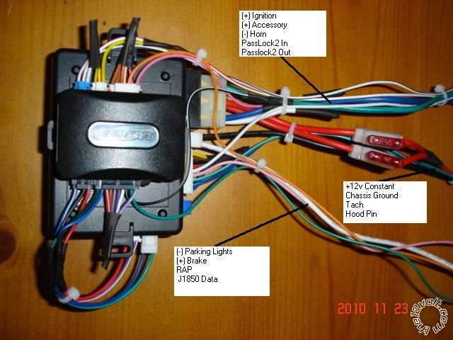
Here is a picture of an Ultra Start Remote Start / Keyless unit ( no alarm ) in W2W mode with an ADS bypass module. There are only 13 wires to connect to the truck.
------------- Soldering is fun!
Posted By: mysticalp
Date Posted: August 01, 2011 at 5:41 AM
kreg357,
Thank-you very much for your response and expertise! I will let you know my progress and result shortly! Your consideration and help is very much appreciated! ------------- Pete
Posted By: kreg357
Date Posted: August 01, 2011 at 7:49 AM
The iDatalink bypass module does an excellent job on that vehicle. The engine starts when it sees this sequence : Ignition wire and Accessory wire simultaneously go to +12V, then the Accessory wire drops ( and the R/S outputs +12v on its unused Starter Output wire ), the engine cranks / starts, Accessory wire goes back to +12V. Most quality remote starters have this timing sequence.
The Canyon / Colorado has real easy access to the under dash area and the necessary wires. It is easier to get the ignition wires at the connector shown above rather that in the steering column. Connect the R/S power wires directly to the battery.
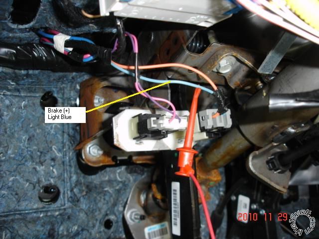
Here are a couple more pictures :
.jpg)
(-) Parking Light Not sure why this picture isn't showing up......... I can EMail it if you need.
Enjoyable vehicle to do. ------------- Soldering is fun!
Posted By: mysticalp
Date Posted: August 01, 2011 at 1:55 PM
Hi Kreg357,
If you can email me the missing picture that would be great. (mysticalpete@hotmail.com). The Autopage unit also has an
*Gnd Output while Running
*Gnd Output when Disarmed
*GND Output when Armed
Are all these connected the same?? ------------- Pete
Posted By: mysticalp
Date Posted: August 02, 2011 at 9:41 PM
Hello,
I have hooked up everything with some success. The remote starter portion is not working. The iDatalink unit flashed ok, then when it was installed it programmed ok too. Now, isn't the gren light on that unit supposed to stay on?? It is off , and I am getting no signal for the remote to start?? any suggestions or ideas?
It is a C3RS915 Autopage
Itms checked: Gnd output when running, gnd, 12V, Tach wire, ACC wire
Now the remote Start unit has 2 Ignition wires and 2 remote start power wires, along with a starter wire. Do I have to connect all of these or just the 1st wire? ------------- Pete
Posted By: kreg357
Date Posted: August 02, 2011 at 10:01 PM
On the heavy gauge wire harness, connect both Reds, the Yellow and the Brown to the correct vehicle wires:
Reds to Battery
Yellow to IGN WHITE/ Green
Brown to ACC WHITE/ Red
Did you wire the iDatalink module W2W or D2D to the AutoPage?
Did you set the iDatalinks' Installation Mode to Data or Standard ( Page 7 of install guide )? ------------- Soldering is fun!
Posted By: mysticalp
Date Posted: August 02, 2011 at 10:32 PM
Hi Kreg,
I just checked the heavy gauge wire harness, both Reds, the Yellow and the Brown are connected to the vehicle wires:
Reds to Battery
Yellow to IGN WHITE/ Green
Brown to ACC WHITE/ Red
I ended up wiring the iDatalink using the Standard method and I also changed the programming method to standard as well. I have tried both ways and am ending up with the same result.... ------------- Pete
Posted By: kreg357
Date Posted: August 03, 2011 at 5:43 AM
Ok. Set for W2W mode, all connections must be made between the iDatalink and the AutoPage as shown in the Type 3 Install Diagram ( dashed and solid lines ). The iDatalink Blue/White Ground When running wire is connected to the AutoPage BROWN / Black GRW wire. The iDatalink ACC and IGN connections can be connected to the AutoPage Yellow and Brown wires ( which then connect to the vehicle ).
The iDatalink module, once flashed with the GM4 firmware, can be Factory Reset when necessary. Try a Factory Reset, set the Install Mode to 2 blinks ( Standard ) and then program to the vehicle doing the 3 second pause at each step.
Not familiar with the AutoPage unit. Does it need to be programmed for Tach, etc? Any error code diagnostics? ------------- Soldering is fun!
Posted By: mysticalp
Date Posted: August 03, 2011 at 6:16 AM
Hi Kreg,
Connections made using the w2w mode. I have not however connected the:
Lock/Arm (-)Input, Unlock/Disarm (-) Input, & the Trunk(-) Input. Do these wires matter whether I hook them up or not? I am not sure as to what wires I would need to hook them up on the Autopage if I did need to? All other connections check.
The Autopage Unit does need to be programmed. I have sent an email with the page on this. This is the sequence that is stated:
1. Turn Ign on/off 3 times and stay in off position. 2. Push valet switch 11 times then hold on 11th until 5 chirps then release. 3. press & release lock/unlock on transmitter at same to set "Tachometer Cheking Type" LED Flash to confirm setting
4 Press & release transmitter unlock once to indicate you are in features "RPM Learning mode" LEd Flash and chirp to confirm this setting.
5. Start the vehicle with the key (while engine is running, the parking led will flash, if it doesn't plase check the Tach (WHITE/ red wire connection.
I do not get step five. nothing happens in terms of th lights or siren chirping. I have connected the Tach wire directly at the Ignition coil. The wire was Orange. (As wiring states not to connect to wire with the colours Black or pink at ignition coil) ------------- Pete
Posted By: mysticalp
Date Posted: August 03, 2011 at 9:13 AM
Ok,
I have chnged the programming on the Autopag to the "Voltage Checking Type" I am much farther ahead now doing it this way!! Now would you be able to tell me how to keep the truck running? It remote starts but doesn't stay running. So basically, the truck turns over (not over -cranking) seems that it starts for a second then shuts off? Any ideas as to what I can do?? ------------- Pete
Posted By: kreg357
Date Posted: August 03, 2011 at 1:46 PM
Passlock2 cuts off the fuel supply to the engine. If it cranks and runs for a second, it sounds like you are not bypassing the Passlock2. Did you cut the Passlock2 wire and solder the correct wires from the bypass to the cut ends?. Did the iDatalink module program as listed in the install guide? Are there any instrument panel lights ( Security ) on during a remote start attempt?
-------------
Soldering is fun!
Posted By: mysticalp
Date Posted: August 03, 2011 at 8:25 PM
Kreg,
Thanks once again! I double checked and had the iDatalink passlock wire on the wrong end of the Vehicle passlock wire. Everything works great!! Thank-you. ------------- Pete
Posted By: kreg357
Date Posted: August 03, 2011 at 8:37 PM
Well done!!  ------------- Soldering is fun!
|