viper 211hv keyless entry is
Printed From: the12volt.com
Forum Name: Car Security and Convenience
Forum Discription: Car Alarms, Keyless Entries, Remote Starters, Immobilizer Bypasses, Sensors, Door Locks, Window Modules, Heated Mirrors, Heated Seats, etc.
URL: https://www.the12volt.com/installbay/forum_posts.asp?tid=128650
Printed Date: April 26, 2026 at 8:19 AM
Topic: viper 211hv keyless entry is
Posted By: axle
Subject: viper 211hv keyless entry is
Date Posted: September 27, 2011 at 10:35 PM
Help! Viper 211HV keyless entry is kicking my butt
Looking for a little guidance here; I'm trying to install the viper 211HV keyless entry in my '92 Chev 3/4 ton Ext Cab. So far, its not going too well.
What I've done so far:
I spliced my ORANGE / Blk hot wire with the Violet & Violet/Blk in the Viper harness.
- spliced the Light Bl with the WHITE/ Blk of the harness
- spliced the BLACK/ Rd with the BROWN / Blk of the harness
- spliced the Gray with the GREEN/ Blk of the harness
- spliced the Tan with the Blue/Blk of the harness.
- connected Red harness to chassis Hot
- connected Blk harness to chassis Ground
The way i currently have it wired, blew the 15A fuse on the Violet/Violet blk harness when i actuated the FOB. Also the passenger door switch doesn't work when I connect the harness to the Viper ECU.
Instructions from the kit are poor at best, there is a small note that states: "The system has door lock relays on-board, and can directly interface with most electric power door lock systems drawing 30 amps or less".
Do i still need Relays to make this kit work? If so, how should it be wired given the layout of this kit?
Below is wiring guide provided by the Viper 211HV:
RED / WHITE (-) OUTPUT OF CHANNEL 2
BROWN / BLACK UNLOCK #87A NORMALLY CLOSED
ORANGE (-) 500 mA GROUND-WHEN-ARMED OUTPUT
YELLOW (+) SWITCHED IGNITION INPUT (ACCESSORY)
WHITE/ BLUE (-) 200 mA CHANNEL 3 VALIDITY OUTPUT
LT. GREEN/ BLACK FACTORY ALARM DISARM
BROWN (-) HORN HONK OUTPUT
BLACK (-) CHASSIS GROUND INPUT
WHITE (+/-) PARKING LIGHT FLASH OUTPUT
VIOLET UNLOCK #87 NORMALLY OPEN (INPUT)
BLUE/BLACK UNLOCK #30 COMMON (OUTPUT)
VIOLET/BLACK LOCK #87 NORMALLY OPEN (INPUT)
WHITE/ BLACK LOCK #87 NORMALLY CLOSED
GREEN/ BLACK LOCK #30 COMMON OUTPUT
BLACK/ WHITE OUTPUT OF DOMELIGHT SUPERVISION RELAY #30
BLACK/ WHITE-1 INPUT OF DOMELIGHT SUPERVISION RELAY #87
BLUE (-) 200 mA SECOND UNLOCK OUTPUT
H1/1 RED (+) 12V CONSTANT POWER INPUT
Thanks for your help!
-------------
I will go and do
Replies:
Posted By: howie ll
Date Posted: September 28, 2011 at 5:20 AM
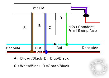
Assuming light blue is lock wire and BLACK/ red unlock and in each case they are at rest at 0v, i.e. ground, when you lock does the following happen? Light blue shows 12v+ and BLACK/ red stays at ground.
When you unlock vice versa?
If so wire as follows:-
211.bmp------------- Amateurs assume, don't test and have problems; pros test first. I am not a free install service.
Read the installation manual, do a search here or online for your vehicle wiring before posting.
Posted By: axle
Date Posted: September 28, 2011 at 9:04 AM
Yes, that is what I determined. Light blue and BLACK/ red are normally at rest, then provide 12volts when I activate my switch. (Lock) light blue, (unlock) BLACK/ red.
-------------
I will go and do
Posted By: howie ll
Date Posted: September 28, 2011 at 9:38 AM
Then that diagram I posted is correct.
-------------
Amateurs assume, don't test and have problems; pros test first. I am not a free install service.
Read the installation manual, do a search here or online for your vehicle wiring before posting.
Posted By: axle
Date Posted: September 28, 2011 at 9:41 AM
Okay, thanx for the diagram. I need to make a slight modification I believe since for my truck, the driver's switch controls the passenger switch and the passenger switch controls the motors. So from driver door light blue to WHITE/ black then GREEN/ black to other end of light blue. Then, RED / black from driver door to BROWN / black and blue/black to other end of RED / black. Does this make sense to you?
-------------
I will go and do
Posted By: axle
Date Posted: September 28, 2011 at 10:18 AM
Yup, that did it. System works as advertised now! Thanx for the help. BTW where did u get the diagram.
-------------
I will go and do
Posted By: howie ll
Date Posted: September 28, 2011 at 10:49 AM
My head, field installation work for 40 + years! A similar one is in the relay section on this site, also your instruction manual should have shown something similar.
-------------
Amateurs assume, don't test and have problems; pros test first. I am not a free install service.
Read the installation manual, do a search here or online for your vehicle wiring before posting.
Posted By: howie ll
Date Posted: September 28, 2011 at 12:50 PM
Updeate, I checked the install guide, it's a joke!
-------------
Amateurs assume, don't test and have problems; pros test first. I am not a free install service.
Read the installation manual, do a search here or online for your vehicle wiring before posting.
Posted By: howie ll
Date Posted: September 28, 2011 at 12:53 PM
Actually, it isn't a joke at all, consider:-
N/Closed = 87a = to the control unit
Normally open = 87 = 12v+ constant
Common = to the doors.
-------------
Amateurs assume, don't test and have problems; pros test first. I am not a free install service.
Read the installation manual, do a search here or online for your vehicle wiring before posting.
Posted By: axle
Date Posted: September 28, 2011 at 3:49 PM
Well, for me the confusing part was the lock/unlock #30 output. I expected this was somehow tying into the motors since it was the #30...I thought those relay pins normally associated with the higher amperage draws of the motor.
-------------
I will go and do
|