python 323, avital 4003, pkh34
Printed From: the12volt.com
Forum Name: Car Security and Convenience
Forum Discription: Car Alarms, Keyless Entries, Remote Starters, Immobilizer Bypasses, Sensors, Door Locks, Window Modules, Heated Mirrors, Heated Seats, etc.
URL: https://www.the12volt.com/installbay/forum_posts.asp?tid=128844
Printed Date: April 26, 2026 at 11:08 AM
Topic: python 323, avital 4003, pkh34
Posted By: superden
Subject: python 323, avital 4003, pkh34
Date Posted: October 14, 2011 at 3:49 AM
Hi, that's my first topic on this forum. So, please, don't judge me too hard  Correct me if I did something wrong 
Here is my problem. I just bought a Python 3203P (model 323) and about to install it myself. I've got wire guide for my 2004 Honda CR-V (thanks to https://www.the12volt.com, but the wire guide I got with alarm is a bit confusing to say at least. Eventually I was able to figure most of wiring out, but diagram doesn't show or explain where I suppose to connect 2 accessory wires from Honda. It shows none! And also what are those "Flex Relays"? How can I use it? Called Directech-no help, they said Pythons intended for only professional installation so they are restricted to give me information on installation! Total BS!!!
Here is what I was able to figure out. If anyone could check if I got it right I would really appreciate! 
PS couldn't upload PDF, sorry
Replies:
Posted By: superden
Date Posted: October 14, 2011 at 4:01 AM
Sorry for quality, but that is the best I could come up with...
Should I just post plain text?
Posted By: superden
Date Posted: October 14, 2011 at 4:22 AM
This one is probably easier to read, sorry for all confusion with my post - 1st timer
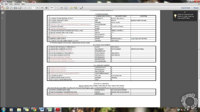
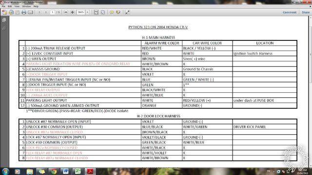
PYTHON 323 ON 2004 HONDA CR-V
H-1:MAIN HARNESS
ALARM WIRE COLOR / CAR WIRE COLOR
1 (-) 200mA TRUNK RELEASE OUTPUT RED / WHITE BLACK / YELLOW (-)
2 (+) 12VDC CONSTANT INPUT RED WHITE
3 (+) SIREN OUTPUT BROWN Siren( +) wire
4 PARKING LIGHT ISOLATION
WIRE-PIN 87a OF ONBOARD RELAY WHITE/ BROWN X
5 (-)CHASSIS GROUND BLACK Ground to Chassis
6 (+)DOOR TRIGGER INPUT VIOLET X
7 (-)TRUNK PIN/INSTANT TRIGGER
INPUT (NC or NO) BLUE GREEN / WHITE (-)
8 (-)DOOR TRIGGER DR.:GREEN(-)DIODE Isolate
INPUT (NC or NO) GREEN PAS.&REAR:GREEN/ RED(-)
9 FLEX RELAY OUTPUT BLACK/ WHITE X
10 (-) 200mA AUX1 OUTPUT WHITE/ BLUE X
11 PARKING LIGHT OUTPUT WHITE RED / YELLOW (+)
12 (-) 500mA GROUND WHEN
ARMED OUTPUT ORANGE GROUND(-)
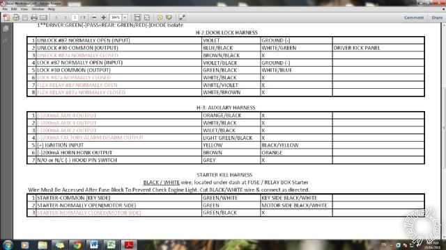
H-2:DOOR LOCK HARNESS
1 UNLOCK #87 NORMALLY OPEN(INPUT) VIOLET GROUND (-)
2 UNLOCK #30 COMMON (OUTPUT) BLUE/BLACK WHITE/ GREEN
3 UNLOCK #87a NORMALLY CLOSED BROWN / BLACK X
4 LOCK #87 NORMALLY OPEN (INPUT) VIOLET/BLACK GROUND (-)
5 LOCK #30 COMMON (OUTPUT) GREEN/ BLACK WHITE/ BLUE
6 LOCK #87a NORMALLY CLOSED WHITE/ BLACK X
7 FLEX RELAY #87 NORMALLY OPEN WHITE/ VIOLET X
8 FLEX RELAY #87a NORMALLY CLOSED WHITE/ BROWN X
H-3: AUXILARY HARNESS
1 (-)200mA AUX 4 OUTPUT ORANGE / BLACK X
2 (-)200mA AUX 3 OUTPUT WHITE/ BLACK X
3 (-)200mA AUX 2 OUTPUT WILET/BLACK X
4 (-)200mA FACTORY ALARM
DISARM OUTPUTLIGHT GREEN/ BLACK X
5 (+) IGNITION INPUT YELLOW BLACK / YELLOW
6 (-)200mA HORN HONK OUTPUT BROWN ORANGE
7 N/O or N/C (-) HOOD PIN SWITCH GREY X
STARTER KILL HARNESS
"BLACK / WHITE wire, located under dash at FUSE / RELAY BOX Starter "
Wire Must Be Accessed After Fuse Block To Prevent Check Engine Light.
Cut BLACK/ WHITE wire & connect as directed.
1 STARTER-COMMON (KEY SIDE) GREEN / WHITE KEY SIDE BLACK/ WHITE
2 STARTER-NORMALLY OPEN(MOTOR SIDE) GREEN MOTOR SIDE BLACK/ WHITE
3 STARTER-NORMALLY CLOSED(MOTOR SIDE) GREEN/ BLACK X
Posted By: superden
Date Posted: October 14, 2011 at 4:27 AM
Sorry, it looked better before posting... I guess it was formatted
Posted By: superden
Date Posted: October 14, 2011 at 4:36 AM

Here is my pdf: https://www.slideshare.net/superden001/excel-worksheet-9691324
Posted By: howie ll
Date Posted: October 14, 2011 at 4:49 AM
Is this an alarm or an R/Start. If you're using it as an alarm the ACC x 2 aren't relevant.
Also on the starter kill harness use 3 instead of 2 it's safer.
Everything else looks OK except the orange GWA. That should NOT be grounded, it's used for triggering accessories such as window closers.
-------------
Amateurs assume, don't test and have problems; pros test first. I am not a free install service.
Read the installation manual, do a search here or online for your vehicle wiring before posting.
Posted By: superden
Date Posted: October 14, 2011 at 1:28 PM
howie ll - Appreciate your help!
Yes, I'm trying to install remote start feature also, bypass module on it's way. Could it be that they moved ACCx2 wires to bypass module harness?
As to Orange GWA-I was told it is used by starter kill...
Where do I connect 3rd wire from starter kill harness?
Thanks
Posted By: howie ll
Date Posted: October 14, 2011 at 1:37 PM
No it isn't. Used for accessories such as window closers. You only need to use 1 and 3 of the starter kill.
You will eventually use the flex relay for ACC 2.
-------------
Amateurs assume, don't test and have problems; pros test first. I am not a free install service.
Read the installation manual, do a search here or online for your vehicle wiring before posting.
Posted By: superden
Date Posted: October 14, 2011 at 1:48 PM
Also no Tach wire on RS/Alarm harness! Doesn't need it?
Is that some kind of new generation alarm? So much confusion with wires...
Posted By: superden
Date Posted: October 14, 2011 at 1:54 PM
You will eventually use the flex relay for ACC 2 - That's what I thought!
But which one ACC1 or ACC2? if both then how?
Man, you are the best! No one ever helped me on other forums
Thank you
Posted By: superden
Date Posted: October 14, 2011 at 2:00 PM
Just received my bypass module! PKH34 It does have 10 pin harness, so I'm guessing I'll find all missing wires here. But it doesn't have Wiring Guide. Can I find it here?
howie ll - Thank you for all your help!
Posted By: kreg357
Date Posted: October 14, 2011 at 8:09 PM
Here is a link to the PKH34 info : https://www.xpresskit.com/product.aspx?productid=212
This module only handles the transponder bypass function. It does not power or control the vehicles ignition wires for a remote start. ------------- Soldering is fun!
Posted By: kreg357
Date Posted: October 14, 2011 at 8:24 PM
Also have some bad news for you. The Python 3203P is an Alarm System with Keyless Entry only. It does not have a remote start ability / function. Its' connection to the Ignition wire is for monitoring purposes only and the connections to the cut Starter wire are for "Starter Kill" security. The PKH34 is not required for this system.
Here is a link to the Python info : https://www.pythoncarsecurity.com/products/product.aspx?Productid=625
Here is a note about remote start capability : Upgradable remote start capability with 4003L ------------- Soldering is fun!
Posted By: superden
Date Posted: October 15, 2011 at 3:18 PM
kreg357 Thanks, if not you - I would be still looking for an answer! Now I got everything clear!
That will teach me to read fine prints all the way down 
Honestly, I was carried away by remote. Neat design and all necessary buttons... I just really wondering who would buy an alarm with HUGE remote and 3 extra buttons just to open/close doors!? Or it's a new trend? 
Posted By: superden
Date Posted: October 15, 2011 at 3:34 PM
Just one more thing! Do I still need Bypass module if get 4003L?
Thanks
Posted By: kreg357
Date Posted: October 15, 2011 at 4:50 PM
Yes, the PKH34 bypass is still necessary for a remote start.
-------------
Soldering is fun!
Posted By: superden
Date Posted: October 16, 2011 at 1:52 AM
Thank you!
Soldering is fun for sure !
Posted By: superden
Date Posted: November 05, 2011 at 2:30 AM
Hi, I'm trying to install all of that (Python 323 / Avital 4003 / PKH34) on my 2004 CR-V. Alarm is installed and functioning fine except that it doesn't go off when I open the hood. Hood pin is installed, but I don't think it's well grounded or does it have to...
Problem is that remote start doesn't work and when I press the button nothing happens, not even an error buzz-buzz from the fob which I was getting if I'd press the button before everything installed(???).
Also can't get this Bypass to work: I connected it via D2D cable which has a power and ground cable to it. So I used only 3 besides D2D (Data, Security Light-Key Side, Security Light-ECM side).
What am I doing wrong?
One more thing-when I installed Avital there wasn't any markings for Activation Input Polarity pin on the case, so (stupid) I assumed it's in (-) by default since 4003 is listed as accessory for Python on web site. So I connected everything and when nothing worked I started to troubleshoot and found out that it was in (+) by default. Is it possible that I burned something inside the unit since it doesn't have any visible fuses? But when I try to access programming menu Avital's LED is blinking corresponding number of times and seems to be in working condition.
Posted By: superden
Date Posted: November 05, 2011 at 4:06 AM
Here is my wire legend:
= to Car; ~ to Alarm, * to RS; # to Bypass; ------ N/C;
Python 323
H-1:MAIN HARNESS
H1/1(-) 200mA TRUNK RELEASE OUTPUT = BLACK / YELLOW side kick panel
H1/2(+) 12VDC CONSTANT INPUT = WHITE ignition Switch Harness
H1/3(+) SIREN OUTPUT = Siren(+) wire
------H1/4 PARKING LIGHT ISOLATION WIRE-PIN 87a OF ONBOARD RELAY
H1/5(-) CHASSIS GROUND = Ground to Chassis
------H1/6(+)DOOR TRIGGER INPUT
H1/7(-) TRUNK PIN/INSTANT TRIGGER INPUT (NC or NO) GREEN / WHITE sec.plug
H1/8(-) DOOR TRIGGER INPUT (NC or NO) = GREEN;GREEN/ RED(DIODE Isolate)
------H1/9 FLEX RELAY OUTPUT
H1/10(-)200mA AUX1 OUTPUT * (+/-) WHITE/ BLUE remote start H1/4 (???)
H1/11 PARKING LIGHT OUTPUT = RED / YELLOW (+) side kick
------H1/12 (-) 500mA GROUND WHEN ARMED OUTPUT
H2:DOOR LOCK HARNESS
H2/1 UNLOCK #87 NORMALLY OPEN (INPUT) = GROUND
H2/2 UNLOCK #30 COMMON (OUTPUT) = WHITE/ GREEN
------H2/3 UNLOCK #87a NORMALLY CLOSED
H2/4 LOCK #87 NORMALLY OPEN (INPUT) = GROUND
H2/5 LOCK #30 COMMON (OUTPUT) = WHITE/ BLUE
------H2/6 LOCK #87a NORMALLY CLOSED
------H2/7 FLEX RELAY #87 NORMALLY OPEN
------H2/8 FLEX RELAY #87a NORMALLY CLOSED
STARTER KILL HARNESS
BLACK / WHITE wire, located under dash at FUSE / RELAY BOX Starter Wire Must Be Accessed After Fuse Block To Prevent Check Engine Light
Cut BLACK / WHITE wire in half & connect as directed
1 STARTER-COMMON (KEY SIDE) = Cut BLACK / WHITE wire
2 STARTER-NORMALLY OPEN(MOTOR SIDE) = Cut BLACK / WHITE wire
------3 STARTER-NORMALLY CLOSED(MOTOR SIDE)
H-3: AUXILARY HARNESS
------H3/1 (-)200mA AUX 4 OUTPUT
------H3/2(-)200mA AUX 3 OUTPUT
------H3/3(-)200mA AUX 2 OUTPUT
------H3/4 (-)200mA FACTORY ALARM DISARM OUTPUT
H3/5 (+) IGNITION INPUT * YELLOW (RS ignition out) (???)
------H3/6 (-)200mA HORN HONK OUTPUT
H3/7 N/O or N/C HOOD PIN SWITCH = COMBINED (ALARM+RS TO HOOD PIN)???
AVITAL 4003
Primary Harness (H1):
------H1/1 (-)FACTORY ALARM DISARM
------H1/2 (-)FACTORY ALARM REARM
H1/3 (+)IGNITION OUT (TO ALARM) YELLOW ~ YELLOW (ALARM H3/5)
H1/4(+/-) ACTIVATION INPUT WHT/BLU ~ WHT/BLU (ALARM H1/10) (???)
------H1/5 GROUND WHEN LOCKED
------H1/6 HORN OUTPUT
------H1/7 TRUNK RELEASE OUTPUT
H1/8 GROUND = GROUND
------H1/9 (+/-) LIGHT FLASH
HEAVY GAUGE RELAY WIRING DIAGRAM
HG1 OUTPUT TO IGNITION CIRCUIT = BLACK / YELLOW
HG2 OUTPUT TO STARTER CIRCUIT = BLACK/ WHITE
HG3 OUTPUT TO ACCESSORY CIRCUIT = BLACK/ RED
HG4 (30A) HIGH CURRENT 12V INPUT = BATTERY DIRECTLY
HG5 PROGRAMMABLE OUTPUT FOR ACCESSORY OR IGNITION = WHITE/ RED
HG6 (30A) HIGH CURRENT 12V INPUT = BATTERY DIRECTLY
"HG5-some 2004 CR-V diagrams showing IGNITION2(WHITE/ BLACK), when 12volts.com says it doesn't exist. So connected it to ACCESSORY2 (WHITE/ RED) of the vehicle, but haven't programmed RS yet. Maybe I should try to check if I have that non-existent IGN2..."
Remote Start Harness (H2):
H2/1(-) NEUTRAL SAFETY SWITCH INPUT
------H2/2 TACH INPUT
H2/3 (+) BRAKE SWITCH SHUTDOWN = CONNECTOR ABOVE BRAKE PEDAL
H2/4 (-) HOOD PIN SWITCH SHUTDOWN = COMBINED (ALARM+RS TO HOOD PIN)
H2/5 (-) 200mA 2ND STATUS/REAR DEFOGGER = T.B.F
"H2/4 - is that OK to connect both HOOD PIN SWITCH SHUTDOWN wires to the same hood pin switch? Just double checking :)"
DOOR LOCK HARNESS
DL1 (-) UNLOCK OUTPUT ~ (ALARM H2/2)
DL2 EMPTY
DL3 (-) LOCK OUTPUT ~ (ALARM H2/5)
4-pin Satellite harness
------S1 (-) STATUS OUTPUT
------S2 (-) ACCESSORY OUTPUT
------S3 (-) STARTER OUTPUT
------S4 (-) IGNITION OUTPUT
Since the installation guide doesn't tell anything about Satellite Harness I am guessing that it's something optional, but still wondering what it is for.
I would really appreciate any help and hopefully it will help someone else too, because it was really a hassle to gain all this information. Especially for a novice. I really thought it would be much easier
Posted By: superden
Date Posted: November 05, 2011 at 4:18 AM
PKH34
wires:
(DATA) VIOLET = WHITE
(SL KEY SIDE) PINK/WHITE = BLUE/ORANGE (KEY SIDE)
(SL ECM SIDE) PINK = BLUE/ORANGE (ECM SIDE)
+ D2D 4pin cable
Manual says that D2D replaces all other connections...
Posted By: dasbogie
Date Posted: November 05, 2011 at 8:27 AM
your neutral safety wire is not listed as connected to anything. It needs to see constant ground in order for the remote start to function. Also, if the hoodpin switch is seeing ground, it will not allow the remote starter to function.
-------------
Advanced
Posted By: superden
Date Posted: November 05, 2011 at 11:25 AM
Thanks
Yes, neutral safety wire is connected to the ground wire.
Hood pin shows ~12V normally and 0V with hood open. Even though I didn't scrape paint under the bolt to make it well grounded.
Is everything else where it should be?
Posted By: dasbogie
Date Posted: November 05, 2011 at 1:04 PM
double check there is not voltage on the brake wire at the remote start. Disconnect the hoodpin briefly to make sure it's not seeing ground. Double check your nss wire that it is seeing ground and if you wired the switch in series, make sure it is switched on. If it's a transponder issue i believe the car will act like the ignition is on but not crank and flash the key light on the cluster. How are you activating the remote start? pulse your WHITE/ blue activation input wire to ground to make sure it isn't the output of your security system.
-------------
Advanced
Posted By: superden
Date Posted: November 05, 2011 at 3:40 PM
You're right, it's a Python that giving me problems. When I pulse-grounded WHITE/ blue,I heard all the relays clicking inside a RS box and car started. When I press a button on the remote I don't hear anything and nothing happens. So I probably have to program/activate remote starter feature on the alarm somehow, what do you think? It doesn't say anything about it in manual
( https://www.the12volt.com/installbay/forum_posts.asp?tid=126090&KW=viper3203 ).
Also can't get bybass to work. Could you please check my wire legend? When I check D2D connection (4pin) shows RED / (+)12.75V; BLACK/ GROUND; BLUE (+)4.86V; GREEN (+)4.97V. So it does get power and has a ground at least - but shows no life at all. LED doesn't lit up or even blink when I am trying to activate or reset it.
Thanks for helping me
|