04 colorado unlock wire weird behavior
Printed From: the12volt.com
Forum Name: Car Security and Convenience
Forum Discription: Car Alarms, Keyless Entries, Remote Starters, Immobilizer Bypasses, Sensors, Door Locks, Window Modules, Heated Mirrors, Heated Seats, etc.
URL: https://www.the12volt.com/installbay/forum_posts.asp?tid=128983
Printed Date: April 11, 2026 at 11:22 AM
Topic: 04 colorado unlock wire weird behavior
Posted By: jaxzin
Subject: 04 colorado unlock wire weird behavior
Date Posted: October 27, 2011 at 8:43 AM
Trying to add a OEM keyless entry alarm add on to my truck. Its the DEI Hornet 727T T. The 04 Colorado calls these wires out for the door lock and unlock.
Doorlocks/Windows
Power Unlock DARK BLUE (-) IN THE DRIVERS KICK PANEL OR PIN A12 IN A BLACK PLUG ATTHE BODY CONTROL MODULE
TO UNLOCK JUST THE DRIVERS DOOR ONLY, PULSE THE WHITE WIRE AT THE BCM, PIN # A12
PowerLock LIGHT BLUE (-) IN THE DRIVERS KICK PANEL OR PIN A11 IN A BLACK PLUG AT THE BODY CONTROL MODULE
Im running into difficulty with the unlocks. The dark blue I have hooked up to the disarm defeat wire on the alarm. That way if someone comes in with a coat hanger and presses the unlock switch at the door the alarm will go off because it senses the wrong unlock wire.
The white wire to disarm the drivers door is weird. I can probe that wire to ground and confirm that it does unlock just the drivers door first thus disarming the alarm but then it has 4.5V on it afterwards. Its interfering with the alarm, it has random disarms on its own and sometimes it goes off for no reason.
Should I use a diode on that line to block the 4.5V coming back the the disarm wire? Perhaps use a relay to boost to a strong ground signal?
Thanks in advance.
Replies:
Posted By: Mike M2
Date Posted: October 27, 2011 at 8:57 PM
You are not reading the instructions correctly. The 727T doesn't connect to the lock/unlock wires, but the motor leg wires. Basically, lock/unlock wires run between the switch and the relays, whereas the motor legs run between the relays and the actuators.
The wires you need are...
GREEN/ lock on the 727T gray, located in the drivers door harness in the DKP
RED / unlock tan, drivers window switch, white 8 pin plug, pin 2
RED / black tan, drivers door harness in the DKP ------------- Mike M2
Tech Manager
CS Dealer Services
Posted By: jaxzin
Date Posted: October 27, 2011 at 10:58 PM
Mike M2 wrote:
You are not reading the instructions correctly. The 727T doesn't connect to the lock/unlock wires, but the motor leg wires. Basically, lock/unlock wires run between the switch and the relays, whereas the motor legs run between the relays and the actuators.
The wires you need are...
GREEN/ lock on the 727T gray, located in the drivers door harness in the DKP
RED / unlock tan, drivers window switch, white 8 pin plug, pin 2
RED / black tan, drivers door harness in the DKP
Thanks. I understand the first two, what are you referencing when you say "RED / black"? Confused since the 727T doesnt have a RED / black wire.
Posted By: jaxzin
Date Posted: October 28, 2011 at 1:56 AM
jaxzin wrote:
Mike M2 wrote:
You are not reading the instructions correctly. The 727T doesn't connect to the lock/unlock wires, but the motor leg wires. Basically, lock/unlock wires run between the switch and the relays, whereas the motor legs run between the relays and the actuators.
The wires you need are...
GREEN/ lock on the 727T gray, located in the drivers door harness in the DKP
RED / unlock tan, drivers window switch, white 8 pin plug, pin 2
RED / black tan, drivers door harness in the DKP
Thanks. I understand the first two, what are you referencing when you say "RED / black"? Confused since the 727T doesnt have a RED / black wire.
OK. So I probed the grey and tan wires for motor lock and unlock. Are these supposed to actuate when pulsed with ground? I get nothng at those wires, and there are like 3 or 4 gray tan wires in the harness.
Posted By: Mike M2
Date Posted: October 28, 2011 at 6:40 AM
Sorry, i was dazed last night when i wrote that and gave colors for AVOX instead of DEI!!!
green is to gray, DKP
blue is to tan, door switch
red is to tan, DKP
The wires are not ground pulses. They are 5 wire, which means they rest at ground and go to 12volts when activated. Do not try to pulse 12volts to these wires as it will cause a dead short.
Some of the tan and gray wires are probably speaker since they are the same color. Use your meter and look for 12volts when you press the remote buttons. ------------- Mike M2
Tech Manager
CS Dealer Services
Posted By: jaxzin
Date Posted: October 28, 2011 at 9:10 AM
Mike M2 wrote:
Sorry, i was dazed last night when i wrote that and gave colors for AVOX instead of DEI!!!
green is to gray, DKP
blue is to tan, door switch
red is to tan, DKP
The wires are not ground pulses. They are 5 wire, which means they rest at ground and go to 12volts when activated. Do not try to pulse 12volts to these wires as it will cause a dead short.
Some of the tan and gray wires are probably speaker since they are the same color. Use your meter and look for 12volts when you press the remote buttons.
Thanks again. I was able to probe and find the 2 wires.
The gray wire that puts out 12Vdc when lock is pressed at the FOB or the switch at the door. ( connect to green wire at alarm module )
Then I found the tan wire that puts out 12Vdc when the unlock switch at the door is pressed but not when the FOB is pressed. This one will go to disarm defeat ( connect to red wire at alarm module )
I am having difficulty finding the pin 2 wire at the 8 pin plug that you mentioned above. Which would be the wire that unlocks just the drivers door with the FOB ( disarm for the module ) It seems that wire does not come out at the DKP. Have you installed one on a Colorado before? If so, how did you get the wire through there or find it because getting through that grommet connector at the door is virtually impossible.
Do I need to use a relay on each of these lines to convert them to a ground pulse? Or do I just hook them up directly to the alarm module?
Posted By: jaxzin
Date Posted: October 28, 2011 at 12:03 PM
OK. I think I may have found a solution for the unlock wire if I'm not able to get it at the door switches since there is vitually no way to pass it through the door grommet.
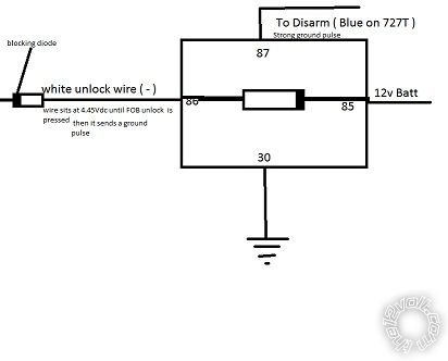
The white unlock wire sits at 4.45Vdc until the FOB is pressed then it pulses a ground. Second press on the FOB pulses ground again but by that time the system will be disarmed already.
What I am going to do is this. I've verified it works perfectly. See any potential problems?

Posted By: Mike M2
Date Posted: October 29, 2011 at 8:13 AM
May work, but 30 should be 12volts to send a 12volt pulse to the 727T.
-------------
Mike M2
Tech Manager
CS Dealer Services
Posted By: jaxzin
Date Posted: October 29, 2011 at 9:18 AM
Mike M2 wrote:
May work, but 30 should be 12volts to send a 12volt pulse to the 727T.
Got ya. I was thinking about that too. I'll keep them all at 12V to the 727T. It works also making the common ( 30 ) on the relay. I've confirmed it.
Once I get the alarm installed I'll report back and give a pinout for getting this installed on the colorado.
I just hate having to mess with that grommet on the door to run just 1 wire.
Posted By: jaxzin
Date Posted: November 14, 2011 at 6:08 PM
OK. So here is how I wired up the 727T to my 04 Colorado.
Main Harness on 727T
Red # to battery at the hidden super fuse cover
Black # to a grounded bolt by the DKP
White # set as ( - ) and attached to brown white at the headlight switch
Green # to GRAY/BLACK (-) and GREEN/ BLACK (-) at the PKP separated by 1N4001 Diodes.
Violet # to Tan 16 gauge wire at the DKP. The tan wire puts out 12V when pressed inside the truck but not with the FOB. This will sense if someone tries to press the unlock button with a coat hanger / wire and sound the alarm.
Blue # to hood pin
Yellow # to WHITE/ GREEN (+) IGNITION SWITCH HARNESS
Brown # to siren
Auxiliary Harness on 727T
Green # to Gray 16 gauge wire at the DKP ( puts out 12V when the FOB is pressed to lock )
Red # to Tan 16 gauge wire at the DKP ( puts out 12V when unlock is pressed inside the truck. This will be the disarm defeat if someone tries to go in with a slim jim / coat hanger or whatever to press the unlock button. That way it can;t be disarmed internally. This line also goes to Violet in Main Harness.
Blue # to white 18 gauge wire at the DKP. The white wire sits at 4.5V at rest and puts out a ground pulse when the FOB is pressed. As a safety measure I used the attached relay schematic to protect any back feed into the truck.
That's pretty much it. Then you have to follow the directions to learn the lock and unlock of the truck to the alarm module. The alarm works good. You can add a battery back up, extra sirens, hook up the horn honk output and add other sensors as you wish. Only thing I had to do is change it from delayed output when the doors are opened because for some reason the truck interferes with that and it had like a double delay of 20 seconds. Now when the doors are opened it immediately sounds the alarm.
Thanks for all your guys help.
|