3 days of trial/error still stumped
Printed From: the12volt.com
Forum Name: Car Security and Convenience
Forum Discription: Car Alarms, Keyless Entries, Remote Starters, Immobilizer Bypasses, Sensors, Door Locks, Window Modules, Heated Mirrors, Heated Seats, etc.
URL: https://www.the12volt.com/installbay/forum_posts.asp?tid=129186
Printed Date: April 08, 2026 at 3:57 AM
Topic: 3 days of trial/error still stumped
Posted By: supern00b
Subject: 3 days of trial/error still stumped
Date Posted: November 11, 2011 at 4:02 PM
Hello, all. I don't mean to be that guy that just comes on to post for help and dissappear but here is my first post lol. I plan on paying this forwards because I have not found enough information on my specific vehicle.
My electrical Background is pretty null, I've set up my sound system and put in my head unit, replaced alternators etc. but when it comes down to installing an alarm i'm pretty baffled.
I'm forcing myself to learn this so that I can do it in the future and be able to diagnose my own problems eventually. (And help others as well.) Before this I knew nothing at all about electronics besides our cars use 12 volt dc and thats what i test for to see if something works.
After literally 20 hours of trial and error/ripping my car apart, testing 100 different wires with my multimeter searching on the internet (Most of my searches led here) I've managed only to get my door triggers to work properly using a diode for one of the wires.
The part where i'm really baffled is the door lock/unlock. It is a one wire system that requires a negative pulse through 1.5k ohm resistor for unlock and just a negative ground pulse for lock. (Maybe the other way around but ill try both and see which one works)
I have a 2002 mazda protege5 and my alarm is a DEI Python 700.
Herein lies my problem. From what i've gathered you need 2 relays for this type of one wire system. Well, this alarm has 2 relays built into it (I found this out after i bought the relays)
I'm stumped as to how and where to place these wires. I tried a few combinations one of them ended up in SMOKE (Wires burning) and the other one ended up unlocking doors only when i touch the wire to bare metal. Now i know why wires are fused! lol. Surprisingly my unit is still intact. This is where i decided that i need help.
Well, the wires on my unit that come out are as follows.
WHITE/ black Lock #87a (Normally Closed)
Greend/black Lock #30 Common (Output)
Violet/Black Lock #87 Normally Open (Input)
BROWN / Black Unlock #87a Normally Closed
Blue/black Unlock #30 Common (Output)
Violet* Unlock #87 Normally open (Input)
*The violet and violet black are joined together at a fuse and end up in one wire at the end.
Which of these wires am i suppoed to connect where? I've searched and searched on relays and different relay combinations and haven't found out what the (Common) Wire is for. or if im supposed to connect them together.
All of the relay searches ive come across just lead me to the types of relays, SPDT and SPST and some other weird crazy ones. i've also already come across the different relay wiring diagrams for wiring to single wire systems but none of them seem to explain where to place my specific type of double relay.
IF someone can help id really appreciate it. I've tried my best on my own and am still stuck. I plan on posting what i've learned into a very understandable format that other people who own a similar one wire system and a similar type of alarm can understand.
Thank you.
Replies:
Posted By: i am an idiot
Date Posted: November 11, 2011 at 4:27 PM
Both common wires to your vehicle one wire. Violet either to ground, or to ground via the 1500 ohm resistor. Violet black gets the other, either ground or ground through the resistor.
Posted By: supern00b
Date Posted: November 11, 2011 at 5:41 PM
Do i put constant 12 volts at any point? or does the alarm power the relays through the 12 volts going through the main harness.
Before i looked at your reply I tried a combination of the common wires at the vehicles single wire, with WHITE/ black and BROWN / black grounded, and violet at constant 12 volt.
I also put the 1.k resistor on the lock wire. Well, this works! locks the car, but if i try and attatch BOTH wires to the one wire it doesn't go off at all, I'm gussing it's because one of the wires sends a positive pulse which nullifies the negative 1.5k resisted negative pulse that locks the door. So i was thinking that maybe i can get a single relay for the unlock wire to send just a straight ground pulse for unlock.
Ill try your method first though before i go into all that other business.
I'm going to try your combinatino right now,
Posted By: howie ll
Date Posted: November 11, 2011 at 6:14 PM
Just do as Mr. I says, alternatively purple and PURPLE / black to ground.
GREEN/ black via 1.5k resistor, join to blue/black then to vehicle wire.
Insulate and don't use WHITE/ black or BROWN / black.
Positive supply to the lock relays is internal to the alarm off the red 5amp supply line.
P.S. The above should be in your alarm instructions, remember RTFM.
-------------
Amateurs assume, don't test and have problems; pros test first. I am not a free install service.
Read the installation manual, do a search here or online for your vehicle wiring before posting.
Posted By: supern00b
Date Posted: November 11, 2011 at 6:42 PM
Trust me i went through every page of that manual. It only states that how the wires are correlated to the internal relay. and that it can "Directly interface with most door lock systems drawing 30 amps or less"
I appreciate the advice guys. It also has 4 auxillary options which i want to make the windows roll down/up or run something else. I'm considering taking a basic electronics class online or in college so i can really understand the why's and the hows and all i would need to make my car do what i want is some relays, motors and wires.
Posted By: supern00b
Date Posted: November 11, 2011 at 6:44 PM
Those were very quick replies and thanks again.
Posted By: supern00b
Date Posted: November 11, 2011 at 7:04 PM
Just tried this and it works!!!!!! Thanks a LOT.
God that's such a huge relief. Now i just have to figure out how to isolate the driver door for progressive unlocking...... ;). another 10 hours here we come.
Posted By: howie ll
Date Posted: November 11, 2011 at 7:15 PM
Trust me you will need 2 x 530t to make all 4 windows close and vent/open and you will need to use your orange ground out (GWA) wire and one aux to control that function.
Also trust me in that the only way to learn is hands on and understanding current flow (on DC work), diodes and relays.
Reading the diodes and relay section in this site will accomplish a lot.
-------------
Amateurs assume, don't test and have problems; pros test first. I am not a free install service.
Read the installation manual, do a search here or online for your vehicle wiring before posting.
Posted By: oldspark
Date Posted: November 11, 2011 at 7:52 PM
Hey supern00b - thanks for your thanks, and replying that it works.
Alas I keep telling that "idiot" that he isn't (and that I want his name!) and as to Howie - what can I say - is he ever wrong?
I've probably just popped in spurred by recent events on this forum...
I have nothing of value to add other than nice to read that you get solutions here, and that the advice you get - especially from the above - are probably bang on. (I should say "will be" band on!)
Don't reply to this - save it for the confirmation that the 2 x 530t etc works, else related question.
Good Luck!
Posted By: i am an idiot
Date Posted: November 11, 2011 at 8:52 PM
Howie, where did the windows come from?
Posted By: howie ll
Date Posted: November 12, 2011 at 3:41 AM
Craig, on the poster's third post.
Also could you email me please, we need to talk, Oldspark knows what it's all about.
-------------
Amateurs assume, don't test and have problems; pros test first. I am not a free install service.
Read the installation manual, do a search here or online for your vehicle wiring before posting.
Posted By: howie ll
Date Posted: November 12, 2011 at 4:02 AM
The driver's door motor wire will be a wire coming from the lock module and running into the driver's door, probably the best test place is if there's a plug in the driver's kick panel.
With your meter, 20VDC setting, place the black probe to a good ground and test the suspect wire with the red, it should go to 12v+ for 0.8 seconds on unlock. Then still with your black on ground set the meter to continuity buzzer or low ohms, it should read ground at rest* that's the driver door unlock.
Physical test, cut that wire, then with the doors locked, flash it to a 12v+ constant, it should only unlock the driver's door.
*Alternative test; with DMM set to 20VDC, place black probe on wire and red to 12v+ constant, you should get 12v+ at rest and 0V on unlocking.
I'll post a diagram.
-------------
Amateurs assume, don't test and have problems; pros test first. I am not a free install service.
Read the installation manual, do a search here or online for your vehicle wiring before posting.
Posted By: howie ll
Date Posted: November 12, 2011 at 4:50 AM
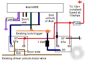
Here we go, you will need 2 relays and a 1N4004 diode.
I've used DEI wiring where known except the "second unlock" or aux, early versions nominated a second unlock wire, later versions just let you use a particular aux; see your instructions.
I've "assumed" orange as the lock/unlock multiplex trigger wire you now have and brown as the existing motor wire because they look pretty!
Don't forget the 1N4004 diode inline on the 85 wire to the right hand relay, it might save the life of your R/S, relays spike on shut down and send a couple of hundred volts back up that line, Mr I graphically explained that once.
Your vehicle will lock all the doors as normal; on unlock the left hand relay operates as a "5 wire" to break the ground continuity (see my last post) and feed pos to the motor. On the second unlock pulse the right hand relay feeds through the resistor to the existing lock/unlock trigger wire to unlock the other doors.
Look at, read and try to "catch" the current flow:- multiplex_priority_unlock.bmp------------- Amateurs assume, don't test and have problems; pros test first. I am not a free install service.
Read the installation manual, do a search here or online for your vehicle wiring before posting.
Posted By: howie ll
Date Posted: November 12, 2011 at 4:56 AM
The driver's door motor wire will be a wire coming from the lock module and running into the driver's door, probably the best test place is if there's a plug in the driver's kick panel.
With your meter, 20VDC setting, place the black probe to a good ground and test the suspect wire with the red, it should go to 12v+ for 0.8 seconds on unlock. Then still with your black on ground set the meter to continuity buzzer or low ohms, it should read ground at rest* that's the driver door unlock.
Physical test, cut that wire, then with the doors locked, flash it to a 12v+ constant, it should only unlock the driver's door.
*Alternative test; with DMM set to 20VDC, place black probe on wire and red to 12v+ constant, you should get 12v+ at rest and 0V on unlocking.
I'll post a diagram.
-------------
Amateurs assume, don't test and have problems; pros test first. I am not a free install service.
Read the installation manual, do a search here or online for your vehicle wiring before posting.
Posted By: howie ll
Date Posted: November 12, 2011 at 4:59 AM
Errata!!!
The last two posts are in the wrong bloody order, also where I mention the second lock wire OR an aux and show it as a violet/black on my diagram, this should be wire H2/1 light blue, listed as second lock wire.
One day I'll actually look at the install guide BEFORE doing the diagram.
-------------
Amateurs assume, don't test and have problems; pros test first. I am not a free install service.
Read the installation manual, do a search here or online for your vehicle wiring before posting.
Posted By: supern00b
Date Posted: November 12, 2011 at 2:30 PM
Wow thanks howie, I think i already have a relay and a diode as well, However i'm not sure what type of diode it is but i can always go to the electronics store and ask them for that specific type of diode.
When you first started were you as lost as i am or did someone teach you the ins and outs of this?
Posted By: oldspark
Date Posted: November 12, 2011 at 5:23 PM
If you were asking me, I'd say I'm too old to remember and that Howie is older than me... But Howie has a great memory.
I'd simply say that most of us are not born with it. (The 2002 Mazda Protege5 is definitely NOT in my genetic memory!)
We all start somewhere.
And how we get "here" is irrelevant, though the lucky or talented will have had others to learn from or been able to think and question and improve.
Eventually we all strike a new car or problem. Then it's a case of reduction - break it into segments (whether testing, or tracing; solve & learn one segment/section at a time).
Keeping "the big picture" in mind - ie, the overall (expected) circuit - is often an advantage provided that doesn't confuse the issue.
One advantage is knowledge. I often say that everything is the same - only different. That seems to come when you know enough to see the similarities, but even when beginning, it helps to draw analogies between with what you already know. (Electricity as water comes to mind.)
Unfortunately with knowledge, people forget the early learning. Though my fellow students once said I had my "head in the clouds" (and it was only some years ago I realised how absolutely correct they were LOL! - and they are still "down there"!), I am amazed that they cannot relate to the difficulties of early learning. I still feel and understand the "trickiness" of clicking to a concept or "having the penny drop" and take great or excessive pains to overcome that.
I could go on about the similarly parallel but incorrect ideas people have that only become evident with some high-level or detailed problem/discussion. I still have "path resets". (One example is oil-pressure controlled gasoline fuel pumps for vehicles. It took me 30 years to see how flawed that was. But smaller "resets" are not uncommon.)
We all learn differently. I seem to be able to see or understand the high-order concept or desire whilst being able to apply or learn the detail. IMO having "both ends" is not only advantageous, but very important.
But the basics and detail are the most important from "our" POV as hobbyists and installers etc.
A bit at a time, and with good solid information.
And always a wariness for the new, the misunderstood, and false egotism...
I'll leave it to Howie to disagree.
I just figured I'd get in before he gets up LOL.
Posted By: howie ll
Date Posted: November 12, 2011 at 5:50 PM
I partly disagree, I've had no formal training but years of experience, I know diodes and relays back to front, more type of relays from Jadeco to Bosch than you could imagine but can I test a transistor or design a circuit to include an NPN?
Of course not, I leave that to Mr. Oldie, Mr. Pierson amd Mr. Idiot.
Forget it but I can "SEE" current flow; back to the water analogy.
I'm lousy with my hands but like circuit design I always find someone to "put that A pillar trim back".
I'm a super fast learner and I still play mind training games even at my age, practising memory retention, I can still list the wiring configuration for the original Minis.
You learn by rote and mistakes, the trick is to damage limit the mistake and avoid it the next time.
If your diode is 1 amp or more and 100piv, then you're OK.
-------------
Amateurs assume, don't test and have problems; pros test first. I am not a free install service.
Read the installation manual, do a search here or online for your vehicle wiring before posting.
Posted By: oldspark
Date Posted: November 12, 2011 at 6:24 PM
Dang! He's up already... Rats.
But Howie "partly disagrees". Rubbish - you DO remember!
No - I don't think Howie disagrees - I think I understated and even omitted self-education...
And that is strange considering how I consider that the most important.
Or rather, that qualifications do not mean knowledge and expertise.
Despite my uni degree and post-grad qualifications, I received my education BEFORE that. There is little I can attribute to later formal education except for maths (hence I know of - but have never since used - Fourier transforms, s-domain analysis, complex integration, etc), and the post-grad marketing and business stuff.
uni was a nice way of understanding what I had been doing in practice those years before. But when I pointed out that pracs have been incorrectly answered for years etc etc.
Let's say I had little choice but to continue my "self education"!
But I just wanted to "not disagree" with Howie and correct my omission.
And say "listed to Howie".
And to sarcastically point out that despite all my gaff - who answered your question...?
1A 100PIV or greater...
Not that I EVER get distracted!
Posted By: howie ll
Date Posted: November 12, 2011 at 6:33 PM
Back to the point of hands on is the best education.
You WILL make mistakes, just learn from them. The person who claims never to have made a mistake is either delusional or a bloody liar!
Don't panic, it's 12:31 am here and for the next 90 minutes we're 6 hours ahead of US Eastern Seaboard and about 10 hours behind you; so I ain't gone to bed yet.
-------------
Amateurs assume, don't test and have problems; pros test first. I am not a free install service.
Read the installation manual, do a search here or online for your vehicle wiring before posting.
Posted By: howie ll
Date Posted: November 12, 2011 at 6:37 PM
No soccer today, we beat Spain 1-0,big deal, I meant no club football and I've been catching up on Terra Nova, Spielberg Presents, Castle and a couple of British dramas.
Terra Nova on HD,YES.
-------------
Amateurs assume, don't test and have problems; pros test first. I am not a free install service.
Read the installation manual, do a search here or online for your vehicle wiring before posting.
Posted By: oldspark
Date Posted: November 13, 2011 at 2:00 AM
howie ll wrote:
The person who claims never to have made a mistake is either delusional or a bloody liar!
Reminds me of the snoboarder...
" Did you fall over?"
"No"
" Then you ain't trying hard enough!"
Besides, you learn more from mistakes.
Allegedly...
Posted By: i am an idiot
Date Posted: November 13, 2011 at 6:35 AM
Howie, I just noticed your request. Let me go check my mail.
googlemail
Posted By: howie ll
Date Posted: November 13, 2011 at 6:44 AM
Craig, I'll email you now.
-------------
Amateurs assume, don't test and have problems; pros test first. I am not a free install service.
Read the installation manual, do a search here or online for your vehicle wiring before posting.
|