Power Window Kit, Wiring Diagram Lost
Printed From: the12volt.com
Forum Name: Car Security and Convenience
Forum Discription: Car Alarms, Keyless Entries, Remote Starters, Immobilizer Bypasses, Sensors, Door Locks, Window Modules, Heated Mirrors, Heated Seats, etc.
URL: https://www.the12volt.com/installbay/forum_posts.asp?tid=129190
Printed Date: April 10, 2026 at 11:34 PM
Topic: Power Window Kit, Wiring Diagram Lost
Posted By: laserbeak43
Subject: Power Window Kit, Wiring Diagram Lost
Date Posted: November 11, 2011 at 9:22 PM
I lost my power window conversion kit wiring diagram. How hard would it be to do this job without it? Almost have a bachelors in electronics engineering....and the closest thing i see to a logic circuit is the switch. everything else is wires, and a fuse on the power lead.
Replies:
Posted By: laserbeak43
Date Posted: November 11, 2011 at 9:22 PM
did i say hello? :)
Posted By: i am an idiot
Date Posted: November 11, 2011 at 9:50 PM
Does the wire with the fuse have the connectors on it to allow it to be connected to 2 different terminals on the switch?
Posted By: laserbeak43
Date Posted: November 11, 2011 at 10:03 PM
i am an idiot wrote:
Does the wire with the fuse have the connectors on it to allow it to be connected to 2 different terminals on the switch?
just one length of wire with a fuse in between, that connects to a wiring harness that connects to the switches (1 power/lock and 4 window)on the armrest.
Posted By: i am an idiot
Date Posted: November 11, 2011 at 10:22 PM
How many connections on each window switch?
Posted By: laserbeak43
Date Posted: November 12, 2011 at 4:32 AM
from what i can see there's a red +, 2 black -, and one for up and down. or is that what the two negatives are for?
Posted By: howie ll
Date Posted: November 12, 2011 at 5:10 AM
Stop! Go no further, this is factory and who knows what's in the module, Get that diagram, we can't guess.
-------------
Amateurs assume, don't test and have problems; pros test first. I am not a free install service.
Read the installation manual, do a search here or online for your vehicle wiring before posting.
Posted By: laserbeak43
Date Posted: November 12, 2011 at 6:27 AM
i could test the leads with a logic analyser and see what they do...
Posted By: laserbeak43
Date Posted: November 14, 2011 at 6:35 PM
havent tried the logic analyser yet,
but i did get the diagram... even though it doesnt tell you what kinds of diodes to use.
any suggestions?
Posted By: howie ll
Date Posted: November 14, 2011 at 6:59 PM
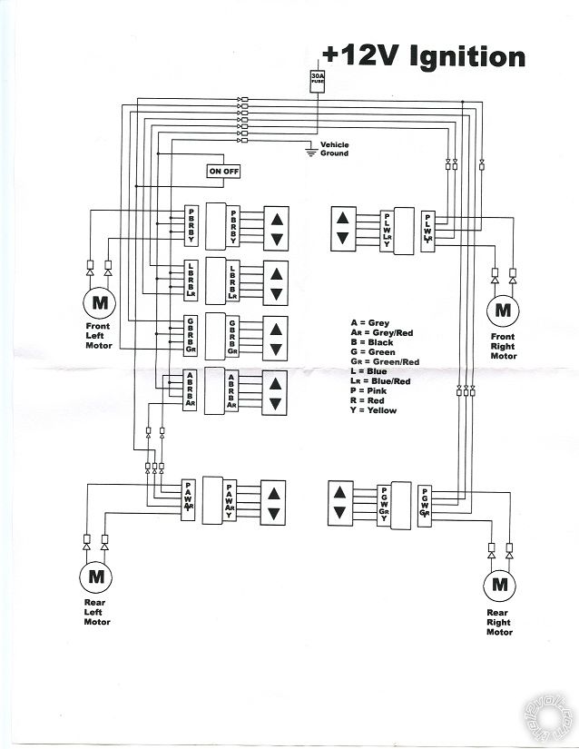
This is a bog standard window system type "A" negative at rest. Same wiring as most vehicles without comfort control or one touch.
What diodes? There aren't any in that diagram, incidentally what logic probe? All you would need for this set-up is a 12v test light.
-------------
Amateurs assume, don't test and have problems; pros test first. I am not a free install service.
Read the installation manual, do a search here or online for your vehicle wiring before posting.
Posted By: laserbeak43
Date Posted: November 15, 2011 at 7:06 AM
howie ll wrote:
What diodes? There aren't any in that diagram
I assumed that those symbols between the leads were variations of this one?

howie ll wrote:
incidentally what logic probe? All you would need for this set-up is a 12v test light.
oh, i was under the impression that i was told to stop cause the switches might contain digital logic.
Posted By: howie ll
Date Posted: November 15, 2011 at 7:16 AM
No they are connectors, if you look closely they are nothing like the diagram you just posted, also some would logically (intended pun) be reversed.
I agree with your logic probe comments but horses for courses, that diagram is exactly how I would (and have over the years) wire a 4 window set up.
The switches are all DPDT momentary, with the motor wires grounded at rest. No door modules, no one touch etc.
The satellite switches are all wired in series with the master switches (driver's door), even the cut out is how I would do it so the driver's door still works all.
Having said that there are later set-ups, especially Japanese, Toyota, Nissan etc. and the Germans, using CAN or 1 wire data from master to slave switches.
-------------
Amateurs assume, don't test and have problems; pros test first. I am not a free install service.
Read the installation manual, do a search here or online for your vehicle wiring before posting.
Posted By: laserbeak43
Date Posted: November 15, 2011 at 2:51 PM
Thanks,
I do want to use the switches (toyota) that fit my pontiac vibe and not the ones that came with this kit. I'll have to check the leads and see what i come up with.
Posted By: howie ll
Date Posted: November 15, 2011 at 4:08 PM
I would bet money that wiring isn't compatible with the factory switches. Try Googling Spal or Electric Life or MES to find compatible switches that look like the Toyota switches.
-------------
Amateurs assume, don't test and have problems; pros test first. I am not a free install service.
Read the installation manual, do a search here or online for your vehicle wiring before posting.
Posted By: laserbeak43
Date Posted: November 17, 2011 at 4:29 PM
i've just cut slots for the switches i have into my base model armrest plates. I'll try to make some kind of circuit to get the other switches working another day. Thanks for your help.
|