1991 nissan d21 viper 5101
Printed From: the12volt.com
Forum Name: Car Security and Convenience
Forum Discription: Car Alarms, Keyless Entries, Remote Starters, Immobilizer Bypasses, Sensors, Door Locks, Window Modules, Heated Mirrors, Heated Seats, etc.
URL: https://www.the12volt.com/installbay/forum_posts.asp?tid=129276
Printed Date: April 08, 2026 at 1:10 PM
Topic: 1991 nissan d21 viper 5101
Posted By: greazyrider
Subject: 1991 nissan d21 viper 5101
Date Posted: November 18, 2011 at 9:09 AM
Vehicle: 1991 Nissan d21 pickup, 2.4l MANUAL TRANSMISSION
System: Viper 5101
Not a pro, but have experience with other installs.. viper seems to be one of its own..
I have searched, read, re-read, and now want to ask some questions.
Here is the wiring for the system.. please double check me and let me know where I am wrong.
Everything was taped up and ran in the truck, now I just wait to connect them all..
H1, 12 PIN CONNECTOR
H1/1-RED / WHITE- TRUNK RELEASE- NOT USED
H1/2-RED- 12V CONSTANT- WHITE/ BLACK(STEERING COLUMN)
H1/3-BROWN-HORN HONK OUTPUT- RED LEAD FROM SIREN, with a relay to change siren lead to (-)
H1/4-WHITE/ BROWN- LIGHT FLASH- NOT USED
H1/5-BLACK-GROUND- GROUND TO FRAME
H1/6- VIOLET- (+)DOOR TRIGGER INPUT- NOT USED
H1/7- BLUE- FACTORY HORN INPUT- (+)LIGHT GREEN/ BLACK
H1/8- GREEN- (-)DOOR TRIGGER INPUT- RED / BLACK FROM DRIVERS KICK
H1/9- BLACK/ WHITE- (-) DOME LIGHT INPUT- USE DOOR TRIGGER WITH A RELAY- is a relay really needed since my triggers are (-)??
H1/10- WHITE/ BLUE- TURBO TIMER- NOT USED
H1/11- WHITE- PARKING LIGHT OUTPUT- PINK/BLUE(+) RELAY NEEDED
H1/12- ORANGE- GROUND WHEN ARMED- NOT USED
H2, 18-PIN CONNECTOR
H2/1-H2/8- NOT USED
H2/9- VIOLET/WHITE- TACH INPUT- WHERE THE HECK IS THIS INPUT AT?!!? I have gone probing every wire on the ecu looking for the dang thing.. I have a 4 prong connector behind my cluster.. thought that might have been it, but it gave off 12v on one connector and nothing on the other 3.. I also read somewhere that I could wrap it around the coil wire going to the distributor?! just trying to find that thing.
H2/10-H2/16- NOT USED
H2/17- BROWN- BRAKE SHUTDOWN- GREEN/ YELLOW OF BRAKE PEDAL SENSOR
H2/18- BLACK/ WHITE- NEUTRAL SAFETY INPUT(-)- I know that I am to connect this to the e brake cable, so that it is grounded at rest. I would also like to connect it to the neutral switch so that I can make dang sure it is in neutral.. is this coming off the side of the tranny or the top usually? I was going to run a wire from the ebrake and one from the tranny, then connect them both to this input. A little help here.
H3, 8-PIN CONNECTOR
H3/1- PINK- (+) IGNITION 1 INPUT/OUTPUT- BLACK/ WHITE- STEERING COLUMN
H3/2- RED / WHITE- (+)FUSED IGNITION 2- (+)12V CONSTANT??
H3/3- ORANGE- (+) ACCESSORY OUTPUT- BLACK/ BLUE- STEERING COLUMN
H3/4- VIOLET- (+) STARTER OUTPUT- BLACK / YELLOW- both of the wires under the column are connected to the starter output so that it can start when cold. But then one sheet says to out one B/Y wire to the starter output, and one to the Ignition 2 output.. hmmm
H3/5- RED- (+) FUSED IGNITION 1 INPUT- (+)12V CONSTANT??
H3/6- PINK/WHITE- (+) IGNITION 2 OUTPUT- Since both my BLACK / YELLOW wires are hooked to the starter output, is this input not used?
H3/7- PINK/BLACK- (+) FLEX RELAY- NOT USED
H3/8- RED / BLACK- (+) FUSED ACCESSORY/STARTER INPUT- (+) 12V CONSTANT?!
DOOR LOCK, 3-PIN CONNECTOR
I added 2 wire actuators to the doors, then proceeded to use the DEI relay and am left with a purple wire going to a 12V CONSTANT
I just need to make sure that these connections are correct. I know that most of them are, as I pulled diagrams from this site, bulldog, dei's site, and a few others.
I am also wondering about my constant 12V. Am I able to hook them all up to my WHITE/ Black wire under the dash and run them like that? Or do I need to run a wire from the battery, if so, how is that done? Fuse size? One wire that has 4 or 5 constant 12v's connected to it? Also, where am I pulling my constant 12V for the relays?
I think that covers all the issues that I have come up with so far..
I have ran the dmm at all my wires, just am getting confused on a few snagups.
Any and all help will be greatly appreciated.
Replies:
Posted By: kreg357
Date Posted: November 18, 2011 at 6:21 PM
Here are some updates :
H1, 12 PIN CONNECTOR
H1/1-RED / WHITE- TRUNK RELEASE- NOT USED
H1/2-RED- 12V CONSTANT- WHITE/ BLACK(STEERING COLUMN)
H1/3-BROWN-HORN HONK OUTPUT- RED LEAD FROM SIREN, with a relay to change siren lead to (-)
H1/4-WHITE/ BROWN- LIGHT FLASH- NOT USED
H1/5-BLACK-GROUND- GROUND TO FRAME
H1/6- VIOLET- (+)DOOR TRIGGER INPUT- NOT USED
H1/7- BLUE- FACTORY HORN INPUT- (-)LIGHT GREEN/ BLACK
H1/8- GREEN- (-)DOOR TRIGGER INPUT- RED / BLACK FROM DRIVERS KICK
H1/9- BLACK/ WHITE- (-) DOME LIGHT INPUT- USE DOOR TRIGGER WITH A RELAY- is a relay really needed since my triggers are (-)??
H1/10- WHITE/ BLUE- TURBO TIMER- NOT USED
H1/11- WHITE- PARKING LIGHT OUTPUT- PINK/BLUE(+) Set Viper Parking Light Jumper to Positive
H1/12- ORANGE- GROUND WHEN ARMED- NOT USED
H2, 18-PIN CONNECTOR
H2/1-H2/8- NOT USED
H2/9- VIOLET/WHITE- TACH INPUT- Tachometer white (AC) in large conn. by dr. kick ** Set Viper Menu 3, Item 2, Opt 4
H2/10-H2/16- NOT USED
H2/17- BROWN- BRAKE SHUTDOWN- GREEN/ YELLOW OF BRAKE PEDAL SENSOR
H2/18- BLACK/ WHITE- NEUTRAL SAFETY INPUT(-)- I know that I am to connect this to the e brake cable, so that it is grounded at rest. I would also like to connect it to the neutral switch so that I can make dang sure it is in neutral.. is this coming off the side of the tranny or the top usually? I was going to run a wire from the ebrake and one from the tranny, then connect them both to this input. A little help here.
H3, 8-PIN CONNECTOR
H3/1- PINK- (+) IGNITION 1 INPUT/OUTPUT- BLACK/ WHITE- STEERING COLUMN
H3/2- RED / WHITE- (+)FUSED IGNITION 2- WHITE/ BLACK (STEERING COLUMN)
H3/3- ORANGE- (+) ACCESSORY OUTPUT- BLACK/ BLUE- STEERING COLUMN
H3/4- VIOLET- (+) STARTER OUTPUT- BLACK / YELLOW - Steering Column
H3/5- RED- (+) FUSED IGNITION 1 INPUT- WHITE/ BLACK (STEERING COLUMN)
H3/6- PINK/WHITE- (+) IGNITION 2 OUTPUT- BLACK / YELLOW @ Steering Column ** Set Viper Menu 3, Item 8, Opt 3
H3/7- PINK/BLACK- (+) FLEX RELAY- NOT USED
H3/8- RED / BLACK- (+) FUSED ACCESSORY/STARTER INPUT- WHITE/ BLACK (STEERING COLUMN)
The two Starter wires should be isolated. Use the Viper Flex relay to power Starter2.
------------- Soldering is fun!
Posted By: greazyrider
Date Posted: November 18, 2011 at 8:58 PM
Thanks!
Any idea what that Tach wire should read? The only wires I saw were all white (14v at idle) or WHITE/ someothercolor.. and didn't get readings that confirmed the correct volts for a Tach..
Also, the starter wires.. you mentioned one to the flex.. is that to H3/7 Flex relay, or H3/6, like what you have marked?
Posted By: kreg357
Date Posted: November 18, 2011 at 9:31 PM
Tach should read between 0.6V and 5.0V AC. To test, set the DMM to 20V AC scale, Black lead to chassis ground, Red lead to suspect wire. Voltage should rise with RPM's. You could also go to a Fuel Injector or Ignition Coil.
Yes, H3/6 is the Flex relay output. It is marked Ignition2 because that is the Viper program default. H3/2 is the input that supplies the power for that output. ( Basically it's a relay with H3/2 RED / White as Pin 87, H3/6 Pink/White as Pin 30 and H3/7 Pink/Black as Pin 87A. ) ------------- Soldering is fun!
Posted By: greazyrider
Date Posted: November 18, 2011 at 9:52 PM
Ahhh ac.. I kept testing dc... whoops.
Ill test some wires in the morning!
Thanks
Posted By: howie ll
Date Posted: November 19, 2011 at 12:38 AM
If a single coil, that's the best place to go. You will have 2 terminals on your coil marked - and +, 61 and 15, or CB and switch, go to the first in each case. When you switch on the ignition but not engine, one will read 12v+, the other not, the one reading not is the one to use. As a guess the BLACK/ white wire at either coil or engine management. My 2000 Nissan has a NSS at the engined management. Check your pin-outs via a vehicle wiring diagram to see if your management has one, if it does use it and program your R/S as an auto.
Much better than parking brake, let me assure you from good experience.
As for the locking what type of locking system is listed?
I'm guessing one wire open circuit (type F) or add actuator.
-------------
Amateurs assume, don't test and have problems; pros test first. I am not a free install service.
Read the installation manual, do a search here or online for your vehicle wiring before posting.
Posted By: howie ll
Date Posted: November 19, 2011 at 1:30 AM
Just had another look at your post, yes you will need a relay for dome supervision, that dome supervision will be drawing 1 amp per 10watt bulb.
Sorry about my lock comments, didn't read your post too well, that spare wire goes again to a 12volt+ constant.
Ref your fuse question, why not by a multi way fuse box, thick lead from the battery with say a 100 amp maxi at the battery then run into the body and distribute it. Google car fuse holders then look for 6 and 8 way holders.
-------------
Amateurs assume, don't test and have problems; pros test first. I am not a free install service.
Read the installation manual, do a search here or online for your vehicle wiring before posting.
Posted By: greazyrider
Date Posted: November 19, 2011 at 8:13 AM
@howie- I was hoping to have an uncluttered mess and hook them all to my constant 12 under the dash,but realized with all the juice the thing is pulling, id have to go another route..
I've used the maxi fuses, ill look into that.. run a 4 or 6.
Posted By: howie ll
Date Posted: November 19, 2011 at 8:23 AM
It's neater to run a 100 amp at the battery then an 8 way fuse box for example, go to the Raw Components* website and look up fuse holders, that way you keep all the R/S and associated, siren, locks etc. in one place.
I would suggest pos and neg both taken from your battery on an older vehicle.
I got called in once because someone installed a Clifford AG4 to a Mkl Golf circa 1982 and the damn thing wouldn't work, I simply ran all the power and grounds to the battery and soaked the fuse holders in moisture retarder. Worked a treat.
*My Google search keeps taking me back to UK suppliers but that will give you an idea of what I mean.
-------------
Amateurs assume, don't test and have problems; pros test first. I am not a free install service.
Read the installation manual, do a search here or online for your vehicle wiring before posting.
Posted By: greazyrider
Date Posted: November 19, 2011 at 12:16 PM
Yeah. I needed to rethink how that'd look with one wire in one out..
So I would run one in, connect to fuse block, then wiring in from there, and put a fuse in each holder accordingly.
also, I wanted to run my nss since the local shop wants almost as much as a bitwriter costs to switch into auto mode.. thought it'd be safe enough with both nss and brake hooked up? But I am willing to learn from others mistakes, err, findings!
Posted By: howie ll
Date Posted: November 19, 2011 at 1:59 PM
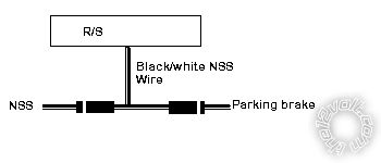
Assuming your vehicle has one...either or gearbox or engine management ECU, use this set up with 2 x 1n4004 diodes, it's belt and braces:- C63_nss.bmp------------- Amateurs assume, don't test and have problems; pros test first. I am not a free install service.
Read the installation manual, do a search here or online for your vehicle wiring before posting.
Posted By: greazyrider
Date Posted: November 19, 2011 at 8:59 PM
ran out of daylight, but everything but the nss/brake is hooked up..
so far so.. alright.
locks work great. up and down smooth.
siren works great with the locking/unlocking.
lights do not flash..
doors lock with the door open.. and no alarm is sounding when i open the hood while the vehicle is armed..so it seems like the trigger is not hooked up properly.
but i probed wires, and found the brown wire puts 12v when the trigger is pushed in. grounded when trigger is out.
so it feels like i have hooked that part right...
and the flash polarity is set to positive.
hmmm
found the tach, .6AC at idle, changes with rpm. also, neutral switch is coming from ecu also.
I'll look into the diode hookup tomorrow.
any ideas with the non-remote start issues at hand?
Posted By: greazyrider
Date Posted: November 19, 2011 at 9:27 PM
did a little looking.. with the parking light flash, am I in need of that relay?
install guide states that with circuits that draw 10 amps or more, the polarity needs to be switched and a relay is needed.
now if i did my math right.. that would 8.4 amps for all the parking lights.
is this correct? that would mean i would not need the relay, maybe that is my issue..
just thinking outloud.
Posted By: howie ll
Date Posted: November 20, 2011 at 1:44 AM
If you directly ground via your DMM or a test light and the lights work, change the polarity of the white output and correct directly, if not report back and I'll tell you how to do it.
Hood switch MUST NOT see ground.
NSS wire MUST see ground.
-------------
Amateurs assume, don't test and have problems; pros test first. I am not a free install service.
Read the installation manual, do a search here or online for your vehicle wiring before posting.
Posted By: greazyrider
Date Posted: November 21, 2011 at 7:37 PM
Ill try that first thing in the morning!
I finished hooking all the wiring up. Changed the Tach option, the starter option, and the transmission to auto.
grounded the nss out and tried to start remotely.
the truck horn blares.
What causes this?!
Also, the Tach will not learn... I am getting .6-7ac at idle, so im not worried about that.. pulled straight from ecu.
Why wont it learn the dang thing?!
Posted By: greazyrider
Date Posted: November 22, 2011 at 3:05 PM
tried the remote start again today.
switched tach to virtual. transmission mode auto.
ran the virtual tach. good. pushed clutch in, pushed button, started right up.
now to make it safe with the clutch(bypass im guessing? hopefully not)...
I never leave it in gear, so I am not to worried about that aspect.. just want to make it safe.. any suggestions? I know howie said to change it to auto and run from the nss.. just wasnt sure on the numbers for that.
The neutral safety coming from the viper unit is putting out 12v with the key out of the ignition. also shows 12 in starting and at idle. I thought this wire is to put out (-) ? I measured my nss coming from the ecu, and it is reading ~4v at rest.
thoughts?
Posted By: howie ll
Date Posted: November 22, 2011 at 4:20 PM
That wire has to see a ground, either through the NSS or the parking brake. If you go to a library or on-line see the engine management pin-outs, that will tell you if it's there connect to that and leave in auto mode.
Or connect to parking brake indicator wire and leave in manual mode.
You will need to by-pass the clutch switch.
-------------
Amateurs assume, don't test and have problems; pros test first. I am not a free install service.
Read the installation manual, do a search here or online for your vehicle wiring before posting.
Posted By: greazyrider
Date Posted: November 22, 2011 at 11:09 PM
so after much research, have come to the conclusion that the neutral switch and the NSS are two different switches.. the neutral switch is my clutch switch, which i thought was the nss coming from the ecu..
anywho, I will attach my nss BLACK/ white output to the ebrake accordingly(ground out when brake is on) and attach the [H2/10- (-) 200mA status output] to my clutch switch(seeing ground when pressed in) with a diode inline, to "bypass" my clutch.
My only problem still, is that the unit WILL NOT learn the tach.
I turn the truck on, within 5 seconds press and hold the valet button..
wait for 3 seconds... NOTHING, no lights, no blinks, no chirps, nothing..
I switched over to auto and virtual tach and it learned the tach just fine...
whats up with it not learning (in manual mode) the tach?!!
|