2009 vibe remote start
Printed From: the12volt.com
Forum Name: Car Security and Convenience
Forum Discription: Car Alarms, Keyless Entries, Remote Starters, Immobilizer Bypasses, Sensors, Door Locks, Window Modules, Heated Mirrors, Heated Seats, etc.
URL: https://www.the12volt.com/installbay/forum_posts.asp?tid=129605
Printed Date: April 08, 2026 at 12:08 AM
Topic: 2009 vibe remote start
Posted By: rnorman3
Subject: 2009 vibe remote start
Date Posted: December 09, 2011 at 7:57 AM
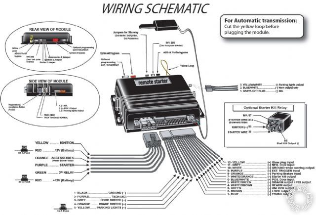
Hi All, I'm new to the forum. I'm buying a basic ProStart CT-3271 (https://www.autostart.ca/prostart/prod-en_CT-3200.php) remote starter for the '09 vibe.
I understand I might need a security bypass? I'm not sure what the '09 vibe has (i.e. PLI, PLII, VATS, etc...). I was checking out the XpressKit bypass system (https://www.xpresskit.com/categories.aspx?categoryid=2) but I'm not sure which one to get. Is this combination going to work (ProStart and XpressKit)?
These two devices will be about $170 total. Is there a better package out there for the 09 vibe?
Thanks,
Richard
Replies:
Posted By: offroadzj
Date Posted: December 09, 2011 at 8:43 AM
As far as the bypass goes, you will need one. If you have access to a XKLoader-2 update device then you can get the xpresskit DB-ALL and it will make life a lot easier. But it needs to be flashed with the proper firmware which requires the XKLoader.
If you do not have access to the XKLoader then you can get the PK-ALL which will do your immobilizer bypass but will not integrate the door locks, or any other feature like the DB-ALL will. It will also require 2 keys to program.
As far as pricing, I've been getting all of my remote start parts (install them on the side) from Amazon. I've been getting the Python 4103 as a nice basic remote start / keyless entry system for around $60. Or you can get the upgraded Python 1401 unit for around $80. Then the bypass is usually around another $60 or so.
-------------
Kenny
Owner / Technician
KKD Garage LLC
Albany, NY 12205
Posted By: rnorman3
Date Posted: December 16, 2011 at 11:42 AM
Hi again, ok, I bought the PK-ALL and the Prostart basic 2 button. I just want to start and stop the car with it.
XpressKit instructions are not clear. For my purposes (start only), will I need to connect the D2D harness between the XpressKit and the ProStart?
Thanks,
RN
Posted By: tedmond
Date Posted: December 16, 2011 at 12:06 PM
the pkall is a rebranded fortin key override all. good bypass to use.
the d2d cable wont do you any good as its only offering ground, 12v and ground when running. i would rather snip off the end and physically connect them.
a compustar pro p1wg4-ss with bypass for 230 if installed by me.
i can help you out if you are in the GTA
-------------
Ted
2nd Year Tier 1 Medical School
Still installing as a hobby...pays for groceries
Compustar Expert
Posted By: rnorman3
Date Posted: December 16, 2011 at 1:49 PM
Thanks, I'll do that.
So I have 2 conenctions (the +12V and GND from the D2D harness after cutting the cable) good stuff.
For the other PKALL connector, it looks like (from the instructions) it needs 4 connections to the car? I'll list them below along with where I think they are supposed to be connected to the car (2009 Vibe):
(1) Rx(Data In):
(2) Tx (Data out):
(3) while running(-):
(4) Key Sense: "Sense Wire (-): 'Dark Blue' Location: Ignition Switch Harness"
Well, actually after looking I don't know where the 1,2,3 wires are. I have all the wiring lists for the '09 vibe from several sites but none have a wire called Data In/Out or "while running"...
Is there another name on these wires?
Thanks,
RN
Posted By: tedmond
Date Posted: December 16, 2011 at 2:26 PM
(1) rx is located at white 7pin plug into the transponder ring. Pin 4
(2) tx located in the same 7 pin plug as rx, pin number 5.
note, you have the correct connector if pin 3 is empty.
(3) while running(-) connect that to the BLUE (-) status output form the python unit.
(4) key sense look for a small white or black connector with 2 wires in it. One will have a WHITE/ black wire and a blue wire. Connect keysense to the blue wire next to the WHITE/ black
-------------
Ted
2nd Year Tier 1 Medical School
Still installing as a hobby...pays for groceries
Compustar Expert
Posted By: rnorman3
Date Posted: December 16, 2011 at 2:49 PM
Thanks Tedmond, question however... Where would I find the transponder ring?
Also, you say 'while running' is BLUE from the Python, however I don't have a Python, I have a ProStart (https://www.autostart.ca/prostart/prod-en_CT-3200.php and attached picture of wiring). I don't see a 'status output' wire from the remote starter. Could this be going to a different wire on this unit?
Posted By: kreg357
Date Posted: December 16, 2011 at 2:55 PM
The transponder ring is on the vehicle at the ignition switch. The PKALL bypass works in Data mode on the RX & TX wires.
-------------
Soldering is fun!
Posted By: rnorman3
Date Posted: December 16, 2011 at 3:32 PM
Thanks again. Sounds like all these wires are in the steering column?
Still though, how about the: "(3) while running(-)" wire from the PKALL.
Where does this connect? I have a prostart remote starter, there's no sign of a "while running(-)" wire coming out of it, unless it's called something else. Here's the wires I have coming from the prostart:

Posted By: buddholly
Date Posted: December 16, 2011 at 3:45 PM
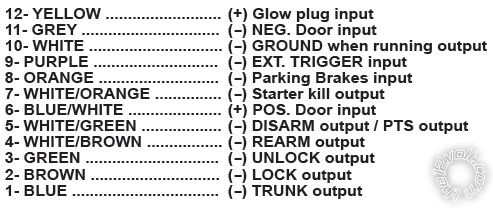
Use 10- White.....(-) GROUND when running output.
-------------
Posted By: rnorman3
Date Posted: December 16, 2011 at 4:09 PM
Excellent, Thanks again all. I think I have it now for connecting the PKALL. Another question about the starter however.
I have 4 harnesses listed above that come out of the ProStart unit. Of those 4 harnesses I'm thinking I don't have to connect every single wire. I'm thinking I can get away with making only the following connections (since I just want to start the car only):
3 Pin Harness
- 1. No connect
- 2. Horn ouput (No connect?)
- 3. Yellow (parking lights output- )
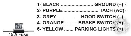
5 Pin Harness
- 1. Black (ground-)
- 2. Purple (TACH/AC)
- 3. Grey Hood Pin Don't connect (use the 'programming assistance' button on unit to program?)
- 4. Orange (brake switch+).
- 5. Yellow (Parking Lights+)
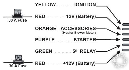
6 Pin Harness
- 1. Yellow (IGN)
- 2. Red (+12V battery)
- 3. Orange (accessories)
- 4. Purple (starter)
- 5. Green (5th relay) No connection required?
- 6. Red (+12V battery)
12 Pin Harness
- 10 only. GROUND when running - output (connect to PKALL)
Does this look correct?
Thanks,
RN
Posted By: buddholly
Date Posted: December 16, 2011 at 4:33 PM
Horn Output - Connect to the horn wire in the vehicle if you want to honk during lock/unlock or to use panic/car finder feature. Not required.
Use either postive or negative parking lights not both, I normally use negative.
Grey Hood Pin should go to the hood shutdown switch. They are included with most remote start systems. You must hook this up for safety reasons.
Green 5th Relay should go the 2nd ignition wire in the vehicle.
-------------
Posted By: rnorman3
Date Posted: December 16, 2011 at 6:08 PM
OK Thanks, almost got it!!! Hopefully just two more questions:
The car has 2 Ignition wires (first IGN+(green) and second IGN+(brown)), but the ProStart only has 1....should I just use the first IGN+ wire from the car?
Then, from the 6 pin harness on the ProStart there are two fused +12V Red wires. Do these need to be run separately all the way to the battery (perhaps to carry enough current)? Or would you tie these together and go to the "Vehicle Battery Positive Wire (+)(Blue or Red) in the ignition Switch Harness"?
Thanks again,
RN
Posted By: tedmond
Date Posted: December 16, 2011 at 9:45 PM
the second ign wire that to green (5th relay output)
run tach and the hood switch. the programming button on the unit is used as a bypass for the hood pin.
-------------
Ted
2nd Year Tier 1 Medical School
Still installing as a hobby...pays for groceries
Compustar Expert
Posted By: rnorman3
Date Posted: December 17, 2011 at 8:11 AM
OK, Thanks again for that. One more thing before I dig into this Vibe's steering column.
There's two separate 30A fused red wires coming from the ProStart remote starter's 6 pin harness.
Should both reds be extended and tied directly to the battery + terminal?
Or can you just join these reds together and run one extension to the battery.
Or can you join them and connect to the "Vehicle Battery Positive Wire (+)(Blue or Red) in the ignition Switch Harness"?
Thanks,
RN
Posted By: buddholly
Date Posted: December 17, 2011 at 5:07 PM
Just tie them in together and run them to the 12v power source in the ignition harness, or the thick white 12v wire in the fuse box.
-------------
Posted By: rnorman3
Date Posted: December 17, 2011 at 5:44 PM
Sounds like a plan. And just one more thing before I start in...there's two starter wires in the car (from the wiring info I have):
Automobile Engine Starter Wire (+): White
Automobile Engine Starter Wire Location: Ignition Switch Harness
Automobile Second Engine Starter Wire (-): Black
Automobile Second Engine Starter Wire Location: Ignition Switch Harness
Looks like a white and a black.
The 6-pin harness from the ProStart remote starter says the purple wire should go to the 'starter' wire of the car. Do I tie this purple from the ProStart to the white starter wire in the ignition switch harness?
Thanks,
Richard
P.S. once I get going i'll be taking some pictures and will attach them to this thread for anyone else wanting to do this same job in the future.
Posted By: kreg357
Date Posted: December 18, 2011 at 3:25 PM
Toyota designed the vehicle to have separate, isolated Starter wires. You should wire in the remote starter to maintain this separation. Unfortunately, to achieve this will require extra 30/40A SPDT relays and 20A fuses. Here is a link to an install guide that has a nice diagram on Page 12 of the proper way to get two Starter wires from one R/S Starter Output. ( This is considering that you have only one GWR output, which is used by the PKALL, and no (-) Starter output. And yes, there are other ways to do this.) https://www.readyremote.com/pdf/manuals/24921.pdf ------------- Soldering is fun!
Posted By: rnorman3
Date Posted: December 18, 2011 at 3:55 PM
Holy c**p! OK, well when I dig into this thing I'll be testing these wires to see how they respond before putting this relay in place. I have a DPDT relay that would work for sure. Will let you know how it goes!
RN
Posted By: rnorman3
Date Posted: December 26, 2011 at 10:26 AM
Hi again guys, I have the remote started connected in the basement to a bread-board just to make sure it's working the way I expect. It all seems to work great. I have the remote programmed etc...
One question, there's a "(3)Yellow/White (-)parking lights output" coming out of a 3 pin harness (next to the horn output). What do I do with this wire?
Thanks,
RN
Posted By: kreg357
Date Posted: December 26, 2011 at 10:46 AM
Depends, are using the Yellow (+) Parking Light output already? You only need
to connect one & it's your choice. Here are the vehicles Parking Light connections from Bulldog.
PARKING LIGHTS ( - ) BROWN (-) @ VEHICLE LIGHT SWITCH
PARKING LIGHTS ( + ) GREEN (+) @ FUSEBOX ,UNDER DASH, PIN 29, WHITE 30-PIN PLUG (A)
If you don't use this wire, insulated it and secure it out of the way. ------------- Soldering is fun!
Posted By: rnorman3
Date Posted: December 26, 2011 at 4:24 PM
OK. However I don't think this thin 22AWG yellow/white parking lights output(-) wire serves the same purpose as the heavy gauge yellow parking lights + wire coming from a different harness. This yellow/white seems to be more of a logic level output, perhaps for a different car model?
Posted By: kreg357
Date Posted: December 26, 2011 at 5:38 PM
The (+) Parking Light output of a remote starter is generally rated at 10 Amps while the (-) Parking Light output is usually only 200mA. On most cars the (+) Parking Light wire does flow a few amps while the cars' (-) Parking Light wire only triggers a relay ( ~90mA ).
-------------
Soldering is fun!
Posted By: rnorman3
Date Posted: December 26, 2011 at 9:42 PM
I figured it would be something like that... Hey check this picture out, it's the output from my TACH (grey wire on the diagnostics connector). I setup the remote starter on the bench to test. All seemed to be working ok. I figured if I injected this same signal (using frequency generator) into the TACH-AC (purple wire of the remote start) (after pressing the start button on the remote) the R/S would disengage the start and ignition wires (i.e. bring them to low) but this did not happen. Instead the R/S continues to supply +12V on the STARTER and IGN wires until the preset time expires and it tries again. If this condition were present when I connected the R/S to the vehicle the starter would just run on until the timer expires even if the car started I believe...
Question: Is it the TACH wire reaching some pre-set frequency (in this case like 30Hz or so) only that tells the R/S the vehicle is started and then to bring the STARTER wire to low?
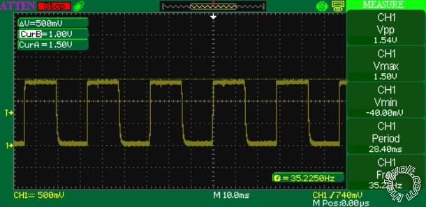
2009 Pontiac Vibe TACH
Posted By: rnorman3
Date Posted: December 27, 2011 at 2:36 PM
OK, got it now for sure. I didn't even know I was supposed to program the TACH using the remote starter so it would recognize the signal. After I did that it all worked good. I've simulated the entire operation of the unit on the bench...without the xpresskit that is. I'm ready to install!!
Posted By: rnorman3
Date Posted: December 30, 2011 at 4:34 PM
Hi again all. I'm in the process of putting this in the Vibe 2009 now. I got the ignition wires exposed. From the wiring instructions I have from "https://www.S P A M.com/2009-pontiac-vibe-keyless-entry-starter-wiring-guide/" is says the green and brown are for the two ignition wires:
Vehicle Ignition Wire (+): Green
Vehicle Ignition Wire Location: Ignition Switch Harness
Vehicle Second Ignition Wire (+): Brown
Vehicle Second Ignition Wire Location: Ignition Switch Harness
In the picture below, are these the brown and green wires they are referring to? (the ones with the red arrows going to them).
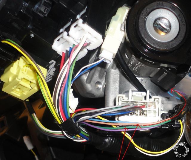
Thanks,
RN
Posted By: rnorman3
Date Posted: December 30, 2011 at 5:57 PM
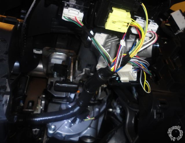
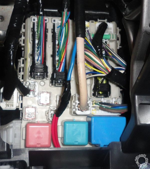
Hi all, I have another thread as well with slightly different question. This one's easy...where is the ignition harness? Some threads specify wire colors for the 2009 Vibe that I can't find up around where the key goes in which is what I thought would have been the ignition harness. Here's two pictures, I'm looking for the two ignition wires and the two starter wires.
Which from another post: "https://www.the12volt.com/installbay/forum_posts.asp?tid=115947" are:
Battery BLUE & RED (+) IGNITION SWITCH HARNESS
Ignition 1 GREEN (+) IGNITION SWITCH HARNESS
Ignition 2 BROWN (+) IGNITION SWITCH HARNESS
Accessory 1 GRAY (+) IGNITION SWITCH HARNESS
Starter 1 WHITE (+) IGNITION SWITCH HARNESS
Starter 2 BLACK (+) IGNITION SWITCH HARNESS
Posted By: rnorman3
Date Posted: January 01, 2012 at 10:14 AM
Thanks for all your help. I managed to figure out the rest of the stuff on my own...I got the starter installed and it works (as long as the key is in the ignition because I'm still waiting on my XpressKit PKALL). Some of the wiring diagrams and info here didn't apply to my Canadian version of the 2009 Vibe so I'm putting a pictorial on the site for anyone wanting to do the same install.
Thanks,
RN - NEWFIE
Posted By: charley b
Date Posted: December 17, 2012 at 1:38 PM
I need help setting up one of these remote starters in a 1996 toyota corolla sedan with automatic transmission...Help greatly appreciated
|