bulldog 500 deluxe anti grind
Printed From: the12volt.com
Forum Name: Car Security and Convenience
Forum Discription: Car Alarms, Keyless Entries, Remote Starters, Immobilizer Bypasses, Sensors, Door Locks, Window Modules, Heated Mirrors, Heated Seats, etc.
URL: https://www.the12volt.com/installbay/forum_posts.asp?tid=129614
Printed Date: April 07, 2026 at 1:10 PM
Topic: bulldog 500 deluxe anti grind
Posted By: micky-b
Subject: bulldog 500 deluxe anti grind
Date Posted: December 09, 2011 at 8:30 PM
Hi guys.
Just installed a Bulldog 500 Deluxe into a 2002 Dodge Dokota, everything works great, the Bulldog 500 seems to be a nice unit, great range, the only thing that I did not install is an Anti-Grind feature, I have found information on wiring the relay for an Anti rind feature, but i`m not sure which wires from the Bulldog 500 to use for the Anti Grind feature, could some-one please help.
T.I.A.
https://www.bulldogsecurity.com/manualsnew/D500installmanuallow.pdf
Replies:
Posted By: 91stt
Date Posted: December 09, 2011 at 10:11 PM
You can use the H7/8 Lt GREEN/ Black wire. Make sure to set it for Start Status. Your relay should wired as follows:
85 = H7/8 + anode side of diode
86 = +12V + cathode side of diode
30 = Starter wire motor side
87a = Starter wire key side
87 = no connection
-------------
This information is provided only as a reference.
All circuits should be verified with a digital multi-meter prior to making any connections.
Posted By: micky-b
Date Posted: December 09, 2011 at 11:46 PM
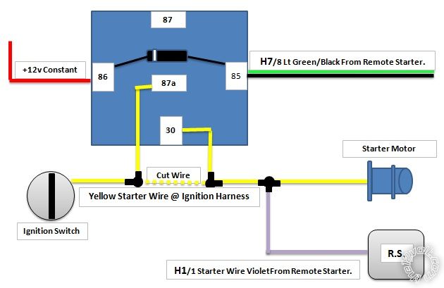
Hi 91stt, many thanks for the reply, does the attached image look correct.
Thank you..
Posted By: lectricguy
Date Posted: December 10, 2011 at 12:11 PM
What you show will work fine for anti-grind.
You could also use the blue/black Ignition3 wire (H7/1) for the anit-grind control without having to change programming. You may also connect the orange ground when armed (H7/10) to the same control wire, giving you a starter kill along with anti-grind.
If you choose to add the starter kill functionality, and there is nothing else wired to either the control wire of your choice or the orange ground when armed, you can directly connect these to each other, and to your relay. If you are using either of these wires for another function (i.e., bypass, sensor enable, etc.) then you would use a diode (such as a 1N4001) in each line and connect the banded end of the diode to the Bulldog signal, and then tie both unbanded ends of the diodes together and also to the relay coil. ------------- Lectric Guy
Posted By: micky-b
Date Posted: December 10, 2011 at 2:32 PM
Many thanks for the replies, I am going to do the anti-grind today..
I`ll post how I got on.
Posted By: lectricguy
Date Posted: December 10, 2011 at 3:37 PM
I just realized you show the relay tied to +12V. You may want to tie this to the IGN wire of your remote start. This will avoid current draw while the car is off--this is particularly important if you do decide to add starter kill.
------------- Lectric Guy
Posted By: micky-b
Date Posted: December 10, 2011 at 6:15 PM
Ok, wired 12v to Ignition wire of remote start and relay as described, works great thanks for your help..
Much appreciated..
Posted By: lectricguy
Date Posted: December 10, 2011 at 7:12 PM
To be clear, you tied the relay to IGN instead of 12V, correct? You would not want to connect 12V to IGN... ------------- Lectric Guy
Posted By: micky-b
Date Posted: December 10, 2011 at 7:49 PM
Yes, I guess I didnt make myself very clear, the 12v Constant in the image I uploaded was tied into the ignition wire not 12v..
Thanks again..
|