I am installing a viper 5501 into a Malibu. I have been out of the remote start/ security business for a good amount of time. That explains why I'm asking for help. Favor for a friend.
I have diagrams for the vehicle, but got a refurb unit and hooked the heavy gauge starter wires I pulled from engine bay (I know there are other ways) but used the RED / black wire and the violet wires on the viper. I have the tach signal and all that because I can valet take over.
I think I have a bad unit. But besides that how can I do the door locks and simulate the key with resistors and which wires? Help on this would be appreciated.
Thanks
Not sure if I understand but I don't think that is how you are supposed to do it. The Starter wire listed in the engine compartment is only used for starter kill, not to start the car. The Viper H3/4 wire is not used for your application. That car will crank the starter after it sees an ignition sequence ( Accessory and Ignition go the +12V simultaneously then Accessory drops to 0V ). The car has one touch starting with anti-grind.
I would recommend something like a DLPK bypass module to go with your Viper R/S. It will handle the immobilizer and the locks, trunk & factory alarm system.
Recently did a 2011 Malibu ( 2008 thru 2011 are the same ) using an Ultra Start U1272 and an iDatalink bypass module.
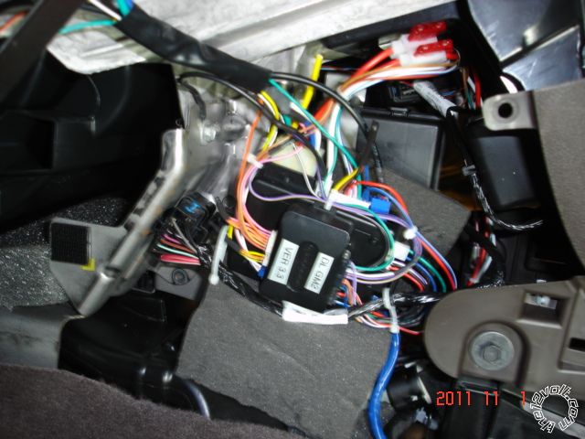
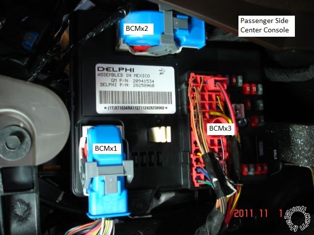
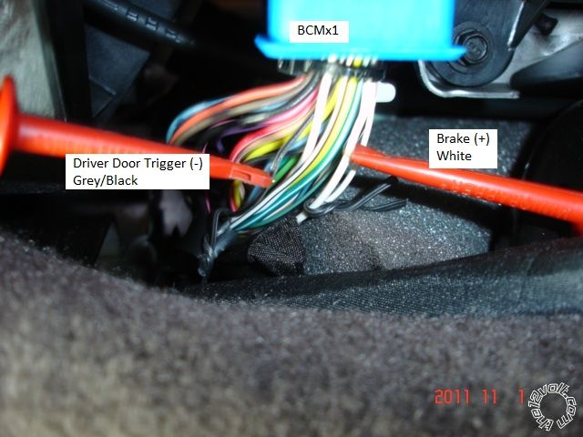
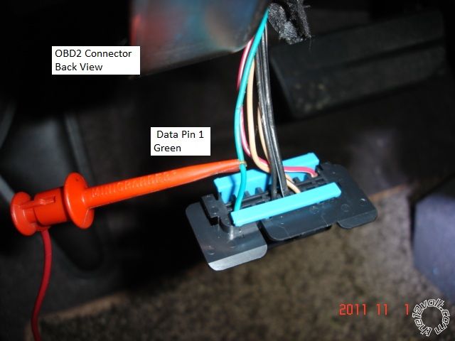
All the necessary connections were at the BCM ( passenger side of the center console ), ignition switch harness and one wire to the OBD2 diagnostics plug.
-------------
Soldering is fun!
Thank you very much, any insight really helps point me in the right direction.
I will get this bypass module and hopefully all goes well.
Here is the wiring for your Viper 5501 & DLPK install into the 2008 Malibu. ( Used the Viper 5301 diagram which I believe is the same as the 5501 )
Went with the W2W setup which slightly more work but extremely reliable. Mate the Viper & DLPK on the bench before install using solder & heat
shrink. Only the necessary connections are listed.
Viper 5501 2008 Malibu DLPK
H1/1 RED / WHITE (-) 200mA AUX/TRUNK RELEASE OUTPUT CN2 RED / White
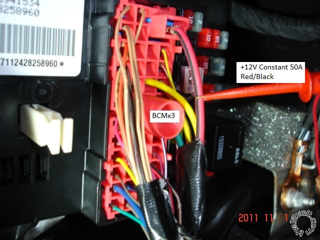
H1/2 RED (+)12VDC CONSTANT INPUT BCMx3 RED / Black CN1 Blue
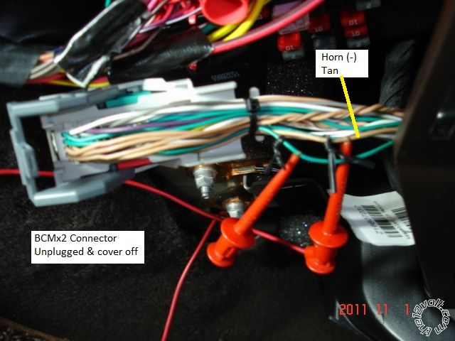
H1/3 BROWN (-) 200mA HORN HONK OUTPUT BCMx2 Tan
H1/4 WHITE/ BROWN PARKING LIGHT ISOLATION WIRE -
H1/5 BLACK (-) CHASSIS GROUND Chassis Ground CN1 Black
H1/6 VIOLET (+) DOOR TRIGGER INPUT
H1/7 BLUE* FACTORY HORN INPUT (Use jumper to set polarity)
H1/8 GREEN (-) DOOR TRIGGER INPUT (N/C** OR N/O) CN2 Green
H1/9 BLACK/ WHITE (-) 200mA DOME LIGHT SUPERVISION OUTPUT
H1/10 WHITE/ BLUE (-) REMOTE START/ TURBO TIMER ACTIVATION
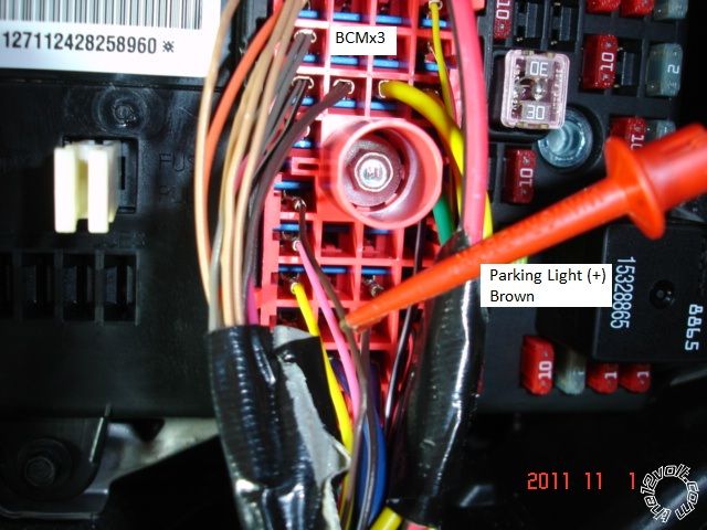
H1/11 WHITE PARKING LIGHT OUTPUT *** set to (+) BCMx3 Brown
H1/12 ORANGE (-) 500mA GROUND WHEN LOCKED OUTPUT
H2/1 LIGHT GREEN/ BLACK (-) 200mA OEM ALARM DISARM OUTPUT
H2/2 ORANGE / BLACK (-) 200mA AUX 4 OUTPUT
H2/3 GREEN / WHITE (-) 200mA OEM ALARM ARM OUTPUT
H2/4 VIOLET/BLACK (-) 200mA AUX 2 OUTPUT
H2/5 WHITE/ BLACK (-) 200mA AUX 3 OUTPUT
H2/6 WHITE/ VIOLET (-) 200mA AUX 1 OUTPUT
H2/7 GREY/BLACK (-) DIESEL WAIT TO START INPUT
H2/8 N/A
H2/9 VIOLET/WHITE TACHOMETER INPUT ***Set Viper to Tach Mode - Menu3, Item2, Opt4 CN2 Violet/White
H2/10 DARK BLUE (-) 200mA STATUS OUTPUT CN2 Blue/White
H2/11 PINK/WHITE (-) 200mA FLEX RELAY CONTROL OUTPUT
H2/12 ORANGE (-) 200mA ACCESSORY OUTPUT
H2/13 PURPLE (-) 200mA STARTER OUTPUT
H2/14 PINK (-) 200mA IGNITION 1 OUTPUT
H2/15 GREY (-) HOOD PIN INPUT (N/C OR N/O) Hood Pin
H2/16 BLUE/WHITE (-) 200mA 2ND STATUS /REAR DEFOG OUT ***Set to 2nd Status Extra Relay
H2/17 BROWN (+) BRAKE SHUTDOWN INPUT BCMx1 White
H2/18 BLACK/ WHITE (-) NEUTRAL SAFETY INPUT Chassis Ground
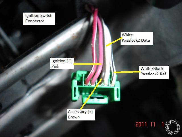
H3/1 PINK (+) IGNITION 1 INPUT/OUTPUT Pink @ Ign Switch *** DLPK guide lists as Yellow
H3/2 RED / WHITE +12V FUSED (30A) IGNITION 2/FLEX RELAY INPUT
H3/3 ORANGE (+) ACCESSORY OUTPUT Brown @ Ign Switch CN2 Pink
H3/4 VIOLET (+) STARTER OUTPUT
H3/5 RED +12V FUSED (30A) IGNITION 1 INPUT BCMx3 RED / Black
H3/6 PINK/WHITE IGNITION 2/FLEX RELAY OUTPUT
H3/7 PINK/BLACK FLEX RELAY INPUT 87a (IF REQUIRED) OF FLEX RELAY
H3/8 RED / BLACK +12V FUSED (30A) ACCESSORY/STARTER INPUT BCMx3 RED / Black
1 BLUE (-) 500mA UNLOCK OUTPUT CN2 Blue
2 EMPTY NOT USED
3 GREEN (-) 500mA LOCK OUTPUT CN2 Light Green
DLPK
CN2 Orange White @ Ign Switch Pin 5 - Key side
CN2 Yellow White @ Ign Switch Pin 5 - Car side
CN3 Light Green OBD2 Green Pin1
CN3 Brown WHITE/ Black @ Ign Switch Pin 6
Pictures :
-------------
Soldering is fun!
Great information as always kreg! im doing my research to take on an 09.
-------------
No better feeling then getting a remote start to work right!
Ah, the power of the search function.  And knowledge is power!
Space is a little tight but a fairly easy car to do with the right bypass module.
Good luck!
-------------
Soldering is fun!
With the IData Module this car is as easy as they get. Glad I switched to Idatalink modules....Rock Solid!!!!!
Kreg357 recommend them with my very 1st install. I fell in love with them.
-------------
No better feeling then getting a remote start to work right!
Great post straight forward I was able to follow your guides and got mine installed on an 09 Malibu with the idataalca model flashed to gm2 but my only question is related to the pin6 which is the white reference wire. if you can please explain how this is supposed to be wired you said brown at cn3 to pin6 but my diagram does show it and I'm not able to locate a brown wire from cn side and instead I have an orange data swc going to green. Guidance would be appreciated thanks
-------------
knowledge is power