2001 gmc yukon xl and clifford 50.7x
Printed From: the12volt.com
Forum Name: Car Security and Convenience
Forum Discription: Car Alarms, Keyless Entries, Remote Starters, Immobilizer Bypasses, Sensors, Door Locks, Window Modules, Heated Mirrors, Heated Seats, etc.
URL: https://www.the12volt.com/installbay/forum_posts.asp?tid=130061
Printed Date: April 09, 2026 at 5:23 PM
Topic: 2001 gmc yukon xl and clifford 50.7x
Posted By: marshallstone
Subject: 2001 gmc yukon xl and clifford 50.7x
Date Posted: January 05, 2012 at 11:47 AM
Hello all,
I have a remote start from clifford 50.7x, a 2001 gmc yukon xl, and a pljx bypass that I want to install. Now, my issues: I have the remote start, but there was no install guide in the box, and I am having trouble finding one online. Also, I want to make sure that the guides posted here for a 2000-2002 suburban will also work for me. I know they are the same vehicle but I want to make sure that all the wiring is the same. Anyhow so I guess I'm requesting for a diagram of the alarm and a diagram of the truck. If anyone could let me know any issues I might run into, that would be great. Also how to wire the pljx... I got the diagram from xpresskit.com and its pretty vague. Any help would be great!!! Thanks,
Marshall
Replies:
Posted By: shortcircuit161
Date Posted: January 06, 2012 at 9:06 AM
I just uploaded the file to the Downloads/Manuals section. Enjoy!!
Posted By: shortcircuit161
Date Posted: January 06, 2012 at 9:15 AM
Hope this helps.
Posted By: shortcircuit161
Date Posted: January 06, 2012 at 9:18 AM
I didn't realize how small the diagram would look. I will post a better copy.
Posted By: shortcircuit161
Date Posted: January 06, 2012 at 9:25 AM
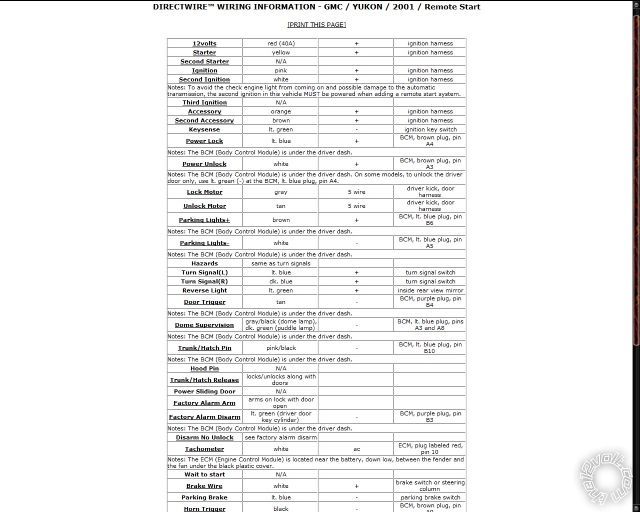
DIRECTWIRE WIRING INFORMATION - GMC / YUKON / 2001 / Remote Start
12volts
red (40A) + ignition harness
Starter
yellow + ignition harness
Second Starter
N/A
Ignition
pink + ignition harness
Second Ignition
white + ignition harness
Notes: To avoid the check engine light from coming on and possible damage to the automatic transmission, the second ignition in this vehicle MUST be powered when adding a remote start system.
Third Ignition
N/A
Accessory
orange + ignition harness
Second Accessory
brown + ignition harness
Keysense lt. green - ignition key switch
Power Lock
lt. blue + BCM, brown plug, pin A4
Notes: The BCM (Body Control Module) is under the driver dash.
Power Unlock
white + BCM, brown plug, pin A3
Notes: The BCM (Body Control Module) is under the driver dash. On some models, to unlock the driver door only, use lt. green (-) at the BCM, lt. blue plug, pin A4.
Lock Motor
gray 5 wire driver kick, door harness
Unlock Motor
tan 5 wire driver kick, door harness
Parking Lights+
brown + BCM, lt. blue plug, pin B6
Notes: The BCM (Body Control Module) is under the driver dash.
Parking Lights-
white - BCM, lt. blue plug, pin A5
Notes: The BCM (Body Control Module) is under the driver dash.
Hazards same as turn signals
Turn Signal(L) lt. blue + turn signal switch
Turn Signal(R) dk. blue + turn signal switch
Reverse Light lt. green + inside rear view mirror
Door Trigger
tan - BCM, purple plug, pin B4
Notes: The BCM (Body Control Module) is under the driver dash.
Dome Supervision
gray/black (dome lamp), dk. green (puddle lamp) - BCM, lt. blue plug, pins A3 and A8
Notes: The BCM (Body Control Module) is under the driver dash.
Trunk/Hatch Pin
pink/black - BCM, lt. blue plug, pin B10
Notes: The BCM (Body Control Module) is under the driver dash.
Hood Pin
N/A
Trunk/Hatch Release
locks/unlocks along with doors
Power Sliding Door N/A
Factory Alarm Arm
arms on lock with door open
Factory Alarm Disarm
lt. green (driver door key cylinder) -
BCM, purple plug, pin B3
Notes: The BCM (Body Control Module) is under the driver dash.
Disarm No Unlock see factory alarm disarm
Tachometer white ac ECM, plug labeled red, pin 10
Notes: The ECM (Engine Control Module) is located near the battery, down low, between the fender and the fan under the black plastic cover.
Wait to start N/A
Brake Wire white + brake switch or steering column
Parking Brake lt. blue - parking brake switch
Horn Trigger
black - BCM, brown plug, pin A9
Notes: The BCM (Body Control Module) is under the driver dash.
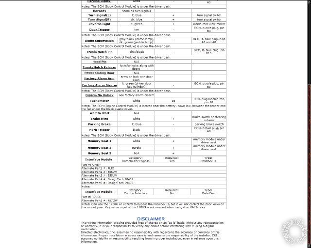
Memory Seat 1 white + memory module under driver seat
Memory Seat 2 purple + memory module under driver seat
Memory Seat 3 N/A +
Interface Module: Category:
Immobilizer Bypass Required:
Yes
Type:
Passlock II
Part #: GMBP
Alternate Part1 #: PLJX
Alternate Part2 #: 556LW
Alternate Part3 #: 555LW
Alternate Part4 #: DesignTech 20402
Alternate Part5 #: DesignTech 29402
Notes:
Interface Module: Category:
Combo Interface Required: No
Type: Data Bus
Part #: 1700G
Alternate Part1 #: 457GW
Notes: Can use the 1700G or 457GW to bypass the Passlock II, but it will not control the door locks on this model year. Key sense input of the 1700G is not needed when using it on GM Trucks
This wiring information is being provided free of charge on an "as is" basis, without any representation or warranty. It is your responsibility to verify any circuit before interfacing with it using a digital multimeter.
Directed electronics, Inc. assumes no responsibility with regards to the accuracy or currency of this information. Proper installation in every case is and remains the responsibility of the installer. DEI assumes no liability or responsibility resulting from improper installation, even in reliance upon this information.
Posted By: marshallstone
Date Posted: January 08, 2012 at 11:19 AM
Thanks for the diagram for the truck. I really appreciate it. What I really needed though was the diagram for the alarm itself. It did not come with one at all.
Posted By: marshallstone
Date Posted: January 08, 2012 at 12:30 PM
Never mind I'm an idiot, I found it in the downloads section... Thanks guys let you know if I have any issues!
Posted By: marshallstone
Date Posted: January 08, 2012 at 4:08 PM
So, I am having difficulties installing this... I'm not sure what the labels on DEI's stuff means, can you or someone else possibly tell me what I need to connect where??? I found all the wires that were on the direct wire diagram inside of the truck. What I don't understand is what wires from the alarm harness I hook where... I'm assuming I have to make the door locks a positive output???
Posted By: shortcircuit161
Date Posted: January 13, 2012 at 6:27 PM
I'm sorry about the late reply. My next post will go into a little more detail about where to connect most of the wires.
Posted By: shortcircuit161
Date Posted: January 13, 2012 at 7:02 PM
On the thick gauge harness (10 pin harness)
Pin H3/1 - Pink - connects to the Pink ignition wire
Pin H3/2 - RED / White - connects to the Red 12v constant wire
Pin H3/3 - Orange - connects to the orange accessory wire
Pin H3/4 - Violet - connects to the yellow starter wire
Pin H3/5 - Green - not used unless you want the starter anti-grind function (optional)
Pin H3/6 - Red - also connects to the Red 12v constant wire
Pin H3/7 - Pink/White - connects to the white 2nd ignition wire (must connect this wire to prevent possible transmission damage or check engine light from coming on)
Pin H3/8 - Pink/Black - (optional) no connection (just cut and tape it)
Pin H3/9 - RED / Black - also connects to the Red 12v constant wire
Pin H3/10 - No Connection
There is also a 2nd Accessory wire (Brown) that will require a relay to power up.
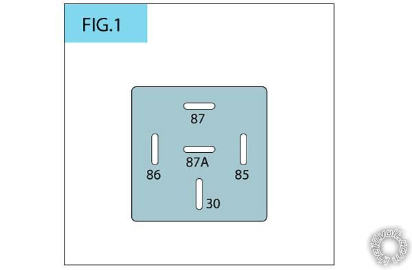
- Connect Pins 30 and 85 to the Red 12v constant wire of the car
- Connect Pin 87 to the Brown 2nd Accessory wire of the car
- Connect Pin 86 to the orange wire (H2/12) of the 18 pin Viper harness
Posted By: shortcircuit161
Date Posted: January 13, 2012 at 7:19 PM
The power lock wires require a positive trigger. The 3 pin lock harness (which only has 2 wires) only gives a negative output so you will need relays or a door module such as the DEI 451M to convert the negative pulses to positive ones.
Blue - unlock output
Green - Lock output
If not using the 451M, you would wire 2 relays like this
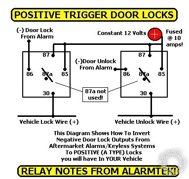
On the Yukon, the power lock wires are in the Brown Plug of the BCM
Lock - Light Blue (pin A4)
Unlock - White (pin A3)
Posted By: shortcircuit161
Date Posted: January 13, 2012 at 7:46 PM
Primay 12 pin harness on the Viper system
H1/1 - RED / White (for trunk) - not used since the trunk unlocks with the rest of the doors
H1/2 - Red - goes to a 12v constant wire (Red from ignition harness)
H1/3 - brown - connects to the red positive wire of the siren
H1/4 - WHITE/ brown - not used (just cut and tape)
H1/5 - black - chassis ground
H1/6 - violet - not used (just cut and tape)
H1/7 - Blue - connects to pink/black for trunk trigger at BCM it's the light blue plug, pin B10
H1/8 - Green - connects to tan door trigger at BCM purple plug
H1/9 - BLACK/ white - connects to gray/black at BCM blue plug
H1/10 - WHITE/ blue - not used
H1/11 - white - connects to negative parking light white wire at BCM blue plug, pin A5 (make sure to set the polarity on the remote start brain to negative trigger for the lights)
H1/12 - orange - not used
Posted By: shortcircuit161
Date Posted: January 13, 2012 at 8:09 PM
The 18 pin harness should be fairly simple but I can post info on that one also if needed. Hope that helps you!
Posted By: marshallstone
Date Posted: January 16, 2012 at 11:48 PM
I could use the 18 pin harness as well but i should be able to figure it out. man great work really appreciate your help!!!
Posted By: shortcircuit161
Date Posted: January 17, 2012 at 8:26 AM
Sure, not a problem at all.
H2/1 LIGHT GREEN/ BLACK (-) 200mA OEM ALARM DISARM OUTPUT
connects to light green at BCM, purple plug, pin B3
H2/2 ORANGE / BLACK (-) 200mA AUX 4 OUTPUT
optional - not needed in this setup
H2/3 GREEN / WHITE (-) 200mA OEM ALARM ARM OUTPUT
arms on lock with door open - you would have to split this wire into two ends and place diodes (1 amp 1N400x) with the band facing the GREEN / WHITE wire. Connect one end to the DOOR TRIGGER wire and the other to the LOCK wire.
H2/4 VIOLET/BLACK (-) 200mA AUX 2 OUTPUT
optional - not needed in this setup
H2/5 WHITE/ BLACK (-) 200mA AUX 3 OUTPUT
optional - not needed in this setup
H2/6 WHITE/ VIOLET (-) 200mA AUX 1 OUTPUT
optional - not needed in this setup
H2/7 GREY/BLACK (-) DIESEL WAIT TO START INPUT
not used for this vehicle
H2/8 BROWN / BLACK (-) 200mA HORN HONK OUTPUT
black wire at BCM, brown plug, pin A9
H2/9 VIOLET/WHITE TACHOMETER INPUT
any fuel injector's uncommon wire OR at the ECM, plug labeled "red", pin 10, The ECM (Engine Control Module) is located near the battery, down low, between the fender and the fan under the black plastic cover. Might just be easier to go to an injector.
H2/10 DARK BLUE (-) 200mA STATUS OUTPUT
used to power the Ground when running input of the bypass unit
H2/11 PINK/WHITE (-) 200mA FLEX RELAY CONTROL OUTPUT
optional - not needed in this setup
H2/12 ORANGE (-) 200mA ACCESSORY OUTPUT
optional - not needed in this setup
H2/13 PURPLE (-) 200mA STARTER OUTPUT
optional - not needed in this setup
H2/14 PINK (-) 200mA IGNITION 1 OUTPUT
optional - not needed in this setup
H2/15 GREY (-) HOOD PIN INPUT (N/C OR N/O)
connects to your hood pin that came with the alarm
H2/16 BLUE/WHITE (-) 200mA 2ND STATUS /REAR DEFOGGER OUTPUT
optional - not needed in this setup (can be setup to turn on the rear defroster but i don't know which wire controls it on your vehicle)
H2/17 BROWN (+) BRAKE SHUTDOWN INPUT
white at the brake switch
H2/18 BLACK/ WHITE (-) NEUTRAL SAFETY INPUT
if it's automatic, connect with your ground. if it's manual, connect to the parking brake wire (light blue wire at the parking brake switch)
Hope that helps!! I'm sorry I didn't post it before. Let us know if you need any other info. It's our pleasure to help you.
|