2007 toyota highlander, remote start
Printed From: the12volt.com
Forum Name: Car Security and Convenience
Forum Discription: Car Alarms, Keyless Entries, Remote Starters, Immobilizer Bypasses, Sensors, Door Locks, Window Modules, Heated Mirrors, Heated Seats, etc.
URL: https://www.the12volt.com/installbay/forum_posts.asp?tid=130188
Printed Date: April 25, 2026 at 3:52 AM
Topic: 2007 toyota highlander, remote start
Posted By: toyo07
Subject: 2007 toyota highlander, remote start
Date Posted: January 13, 2012 at 10:41 AM
Hey all, Im installing a 5704 viper into my Highlander.. well issue is The remote start runs but does NOT crank... Would anyone know the correct color codes for the starter wires on the Highlander? And are both starter wires used and connected to the 2 starter wires on the remote starter? which wires are connected to which?
I have on the Highlander starter 1= black @ igntion ... starter 2 = WHITE/ black... remote starter wires are starter output= violet & starter input= green. Lost with which go where....
Anyone!? Thanks in advance.
Replies:
Posted By: shortcircuit161
Date Posted: January 13, 2012 at 1:15 PM
12volts white (40A), yellow (30A) + ignition harness
Starter BLACK/ white + ignition harness
Second Starter black + ignition harness
Ignition gray + ignition harness
Second Ignition green + ignition harness
Third Ignition N/A
Accessory blue + ignition harness
Second Accessory N/A
Keysense green - ign harn or BECU, 2nd plg dwn, pin 2
Notes: Using the status output from the remote start to trigger this wire will disarm the alarm without unlocking the doors.
You would need to trigger both the BLACK/ white and the black wires to engage the starter. Use a relay to isolate the two from each other.
Posted By: toyo07
Date Posted: January 13, 2012 at 1:40 PM
Sorry lost of what you said... when you say I need to trigger both starter wires... with a relay I dont understand... trigger both with which wires? with both starter input & output (remote starter).. can you explain abit..
Posted By: shortcircuit161
Date Posted: January 13, 2012 at 6:01 PM
The harness from the Viper system only has one thick starter wire (violet i believe). In order to get your car to remote start, you would have to power up both starter wires (BLACK/ white and black)at the same time. You would need to use a relay to power up that second starter wire while the main Viper harness powers up the primary starter wire.
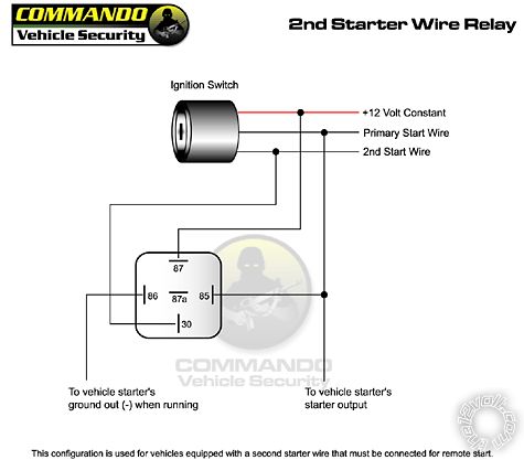
The only thing I would change is connecting Pin 86 directly to ground instead of using the "ground out when running" wire as that one might be used for the immobilizer bypass.
Posted By: aztec06
Date Posted: January 13, 2012 at 7:44 PM
hey thanx so much...... just one other question... on the remote starter there is a STARTER INPUT... now do I not use that wire.. or DO I use it... if so where does that one go... I understand about the 2nd starter wire now.. but I dont know if that starter Input is connected..????
Thanks again.
Posted By: zerepdivad
Date Posted: January 13, 2012 at 7:48 PM
shortcircuit161 wrote:
The harness from the Viper system only has one thick starter wire (violet i believe). In order to get your car to remote start, you would have to power up both starter wires (BLACK/ white and black)at the same time. You would need to use a relay to power up that second starter wire while the main Viper harness powers up the primary starter wire.
The only thing I would change is connecting Pin 86 directly to ground instead of using the "ground out when running" wire as that one might be used for the immobilizer bypass.
No, the proper way is to do this with the Ground when running wire. Otherwise you're triggering the relay every time that you start the vehicle with the key. ------------- A DMM is a beautiful thing.
MECP Advanced Installer Certified.
Posted By: shortcircuit161
Date Posted: January 13, 2012 at 7:52 PM
- if it says starter input (key side), you don't need it.
- if it says starter input 12v, then you would connect that to 12v constant.
What is the color of that wire that is labeled STARTER INPUT?
Generally on the Viper remote start (thick gauge) harnesses, there are 3 red wires. Red, RED / Black and RED / White. All of these would go to a 12v constant on your ignition harness.
In your vehicle, it would connect to either the white (40Amp) or the yellow (30Amp) wire at your ignition harness. That would provide the current needed to power all the ignition, accessory and starter wires.
Posted By: aztec06
Date Posted: January 13, 2012 at 7:57 PM
gotcha zerepdivad, thanx yea thats true.... and shortcircuit161 thanx again... YES that starter input says (KEY SIDE) and its (Green) and yes those are the exact wires I connected to 12v... Im going to try this in abit. need to go buy a few fuse holders.. Thanks guys so much....!! Wife said Thanx hahah....
Posted By: aztec06
Date Posted: January 13, 2012 at 8:10 PM
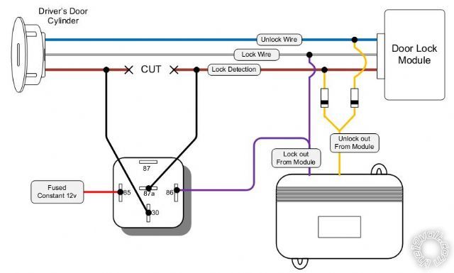
By any Chance do you guys..... know how to wire a Toyota Highlander locks.... I used a diagram provided ... wondering if im doing something wrong.... Heres what I did.. I used 2 diodes and a relay.... I divided the unlock output w/2 diodes one to unlock & other to unlock detection then I cut the unlock detection and placed car side to 87a on relay, other side lock side to #30 on relay, the Lock output to Lock & #86 on relay. & #87 goes to ground & #85 to 12v constant.
Is that correct...
Posted By: shortcircuit161
Date Posted: January 13, 2012 at 9:32 PM
Thank you zerepdivad, I didn't realize that. I'm sorry for suggesting to do it that way.
Posted By: shortcircuit161
Date Posted: January 13, 2012 at 9:45 PM
Lock wire - Green
Unlock wire - Yellow
Lock Detection - Brown
These are located inside the door
Posted By: aztec06
Date Posted: January 13, 2012 at 11:07 PM
Thanks awhole lot.. ok so i went installed it exactly the way it is displayed on the diagram... so The Unlock works great but the LOCK does Not work... it does not lock the doors.... does it matter if its all done right next to the door lock module or does it need to be done right next the lock cylinder?
What can cause it not to Lock.. but it does unlock the door if i lock them with either the wireless remote or @ the door panel.
anyone?!
Posted By: toyo07
Date Posted: January 14, 2012 at 7:34 AM
Hey guys, I have been installing my viper 5704 viper in my highlander and I did the directfax 1070, and the unlock works but the lock doesn't. Can anyone tell me or know why it doesn't lock.... I was messing with it and some how made it work to lock but then it wouldn't unlock. Can anyone help out or know what the problem is.? Thanks in advance.
Posted By: metz35
Date Posted: January 14, 2012 at 8:13 AM
It will only lock if all the the doors are closed. If you are confident you did the relay lock detection diagram right.
Posted By: aztec06
Date Posted: January 14, 2012 at 10:13 AM
Yes ...I made sure all the doors were closed before tried it.. since it didnt lock im lost of why it doesnt.... do anyone know what the issue is?
Posted By: metz35
Date Posted: January 14, 2012 at 10:40 AM
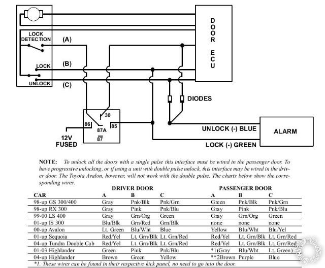
04-up Highlander Brown Green Yellow **2Brown Purple Blue
**2. The passenger side wires are at the BECU behind the glove box, 2nd plug down from the top. They are:
lock - PURPLE in pin 8, unlock - LIGHT BLUE in pin 13, and lock detection - BROWN in pin 11.
NOTE: If you experience a no lock or unlock condition, check the resistance to ground on the keyless/alarm
module. The door lock outputs on all Directed systems are only 200 milliamps and any resistance may cause
the door locks not to work. If you meter less than .001 resistance and the door locks still do not work, use a
relay to increase the ground amperage or contact *******s technical department for assistance.NOTE
Posted By: shortcircuit161
Date Posted: January 14, 2012 at 10:40 AM
Things to check-
-Are you using the GREEN/ blue lock/unlock harness for this?
-Make sure you have no diodes on the lock wire (not needed for this setup)
-test the blue lock wire to make sure you are getting a negative pulse when you hit lock on the viper remote
-double check you are using the correct wires in the door. Test them while turning the key in the door to the lock position
-Make sure you have constant 12v going to pin 85 of the relay
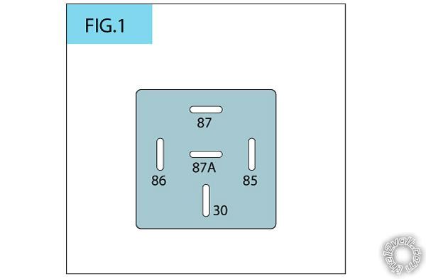
-Check the connections on the relay. Pin 87 should have no connection.
-Do you hear the relay engage or click when you press lock on the remote?
-Ensure you have a good solid chassis ground going to the viper system. You can't imagine the issues you get with a bad ground.
To lock, the relay has to engage to "break" the connection of the Brown lock detection wire AT THE SAME TIME as the Green lock wire gets the ground pulse from the alarm.
Something I would personally try also, (if i felt i had everything wired correctly), is to take a different wire and connect that directly to a good chassis ground and touch the other end to the blue wire from the viper harness. If the doors lock, then it may be a bad ground or a weak ground going through the blue lock wire.
Posted By: aztec06
Date Posted: January 14, 2012 at 11:12 AM
Yes im using the blue/green viper harness... made sure there is no diodes on the lock output.. actually green is the LOCK wire.. so im guessing thats the one I test for a negative pulse when the lock it pressed on the viper alarm? correct?
Ill test for a negative from the lock in a few with the key turned and 12v constant ill also check.. there was a ground wire connected to the 87 but took it off.. and I'll retrace the ground for the viper main unit system.
when you said take a different wire and connect that directly to a good chassis ground and touch the other end to the blue wire from the viper harness.. do you mean blue as in (LOCK wire)?? or unlock wire..? the viper harness color code is Green= LOCK OUTPUT Blue=UNLOCK output.
I hope I didnt fry the lock on the viper module.
Posted By: aztec06
Date Posted: January 14, 2012 at 11:27 AM
Okay just was out there... heres what I've found... tested the Lock and when the doors are unlocked... the locked tested at 7volts... and when locked it also tested at 7 volts from the relay. I Locked with key and unlocked as well. I did try using a grounded wire and nothing happened to the relay... DO you guys think its a BAD Relay? didnt engage how its suppose to.
Posted By: shortcircuit161
Date Posted: January 14, 2012 at 11:57 AM
I'm sorry for the wrong color on the Viper system. Yes I meant the green lock wire from the Viper. Do you have a 12v constant wire going to Pin 85 of the relay?
What I meant about a different wire was an unrelated spare wire just for testing. About 2 feet long or so, connecting one side to a ground connection (bare chassis metal under the dash) either on a screw or with a test clip to hold it in place. The other bare end of the test wire I would touch to where the green lock wire connects to inside the door. Either to Pin 86 at the relay or to the lock wire. Since the green Viper lock wire is already connected, using this "test" wire should automatically provide a ground connection to both the relay and the lock wires.
If your relay isn't clicking or engaging, first check all the connections are wired correctly.
Pin 85 - 12v Constant (test with meter)
Pin 86 - First half of green lock wire from Viper (other half goes to the lock wire)
Pin 87 - no connection
Pin 87a (center) - one half of the lock detection wire
Pin 30 - other half of the lock detection wire
Posted By: aztec06
Date Posted: January 14, 2012 at 5:08 PM
Okay were going to start from the beginning... To test the alarm unlock & lock outputs how would I test for them correctly??? anyone!
Posted By: shortcircuit161
Date Posted: January 14, 2012 at 9:29 PM
Ok to start from the very beginning with the lock/unlock setup
-Take your multimeter and find a 12v constant power feed (probably from the remote starter harness or ignition harness. Possibly at the fuse box)
-Plug or clip your positive test wire from your multimeter to this 12v constant connection.
-You will then use your negative test wire to test each of the lock and unlock wires from the Viper harness. The blue and green ones.
-First connect the negative test wire to the blue unlock wire and press unlock on the Viper remote. Your test meter should quickly show 12v and then 0v again.
-Then try the same test on the green lock wire while pressing the lock button on the Viper remote.
Once you've established that both wires are working correctly by sending ground pulses, you would check the connections made in the door.
-First connect the blue unlock wire from the Viper system that's split into two wires with diodes (bands toward the blue unlock wire); one split to the Brown lock detection wire and the other to the Yellow unlock wire in the car.
-Test that first with the Viper remote to make sure you can unlock the doors.
-Then, connect the relay with
Pin 87 to one side of the Brown lock detection wire
Pin 30 to the other side of the lock detection wire
Pin 85 needs a wire providing 12v constant power (must have this setup for the relay to work)
Pin 86 - see below
-Then from the Green wire from the Viper system, (split into 2 wires), one end goes to Pin 86 of the relay and the other end goes to the Green lock wire in the car.
-Test that with the Viper remote to make sure you can lock the doors.
Here is a different image of the whole setup that may help.
Posted By: Mike M2
Date Posted: January 15, 2012 at 9:52 AM
You can get power for the relay right at the drivers window switch. I think it is a thicker green wire, and this will be one less wire you need to run. A few years back one of my installers ran it thru the boot and it shorted out, cost us a thousand bucks to fix. ------------- Mike M2
Tech Manager
CS Dealer Services
Posted By: zerepdivad
Date Posted: January 15, 2012 at 10:17 PM
I just did one of these yesterday and got my locks in the passengers kick panel. But I imagine at this point you're a bit past that point.
-------------
A DMM is a beautiful thing.
MECP Advanced Installer Certified.
Posted By: aztec06
Date Posted: January 16, 2012 at 1:46 PM
zerepdivad ... did you do it like the diagram displayed on top?? or did you do this a different way? I am going to make the harness .... as above but for the pass. kick panel instead... what colors were used on the passenger side... did you used the harness coming from the BECU or the plug already going inside the Door panel?
Thanks Alot guys for you guy's help... well the drivers side didnt work so I'll be doing this on the other side.. see how it goes... this same setup... Also I was given another method.. going direct with the lock output & unlock output from the remote.. using on the unlock output divide it with 2 diodes one on unlock & other on unlock detection then going direct with the lock. but Im not sure if thats going to work.... if the diagram on top doesnt work.. then if not I'll go and buy the xk01 module instead... I Cant believe im actually struggling with this.. i've done so many different mods on different cars and this one is getting to me...
Posted By: zerepdivad
Date Posted: January 20, 2012 at 7:42 PM
14 pin plug grey and purple. straight negatie triggers. Test to verify as always.
I would hope by now you figured this out though.....
-------------
A DMM is a beautiful thing.
MECP Advanced Installer Certified.
|