1991 toyota land cruiser hdj81 japan spec
Printed From: the12volt.com
Forum Name: Car Security and Convenience
Forum Discription: Car Alarms, Keyless Entries, Remote Starters, Immobilizer Bypasses, Sensors, Door Locks, Window Modules, Heated Mirrors, Heated Seats, etc.
URL: https://www.the12volt.com/installbay/forum_posts.asp?tid=130583
Printed Date: May 14, 2026 at 4:41 PM
Topic: 1991 toyota land cruiser hdj81 japan spec
Posted By: veiloctane
Subject: 1991 toyota land cruiser hdj81 japan spec
Date Posted: February 11, 2012 at 12:14 PM
Looking for a diagram for a 1991 Toyota Land Cruiser Hdj81 Japan Spec Diesel 80 Series
Replies:
Posted By: howie ll
Date Posted: February 11, 2012 at 12:33 PM
The Japanese version will be identical to US/Canadian as regards Alarm-R/S and Audio.
Dead easy to do.
You will need indicators rather than lights, GREEN/ black and GREEN/ YELLOW, POS with steering column loom.
12V+, ACC, Ign. 1 and 2 and starter all in ignition switch loom (test).
Lock and unlock, low current NEG, in white plugs in driver kick panel.
Door triggers and possibly hatch, wire that goes NEG at domelight when a door is opened possibly RED / white, or red with silver dots, also to be found in driver side (assuming right hand drive) floor loom at kick panel.
Tach either at rear of tach gauge if one is present, or use a DEI 454T induction tach generator.
You will need to fit a hood pin switch but you won't need a by-pass.
Headlights and horn, both NEG trigger in steering column loom.
Sorry I can't be more precise but I haven't worked on one of these since about 94!
-------------
Amateurs assume, don't test and have problems; pros test first. I am not a free install service.
Read the installation manual, do a search here or online for your vehicle wiring before posting.
Posted By: howie ll
Date Posted: February 11, 2012 at 12:48 PM
US petrol (gasoline) version is now in the Downloads/Manuals section search as "91 Toyota Land Cruiser".
The wiring should be the same.
-------------
Amateurs assume, don't test and have problems; pros test first. I am not a free install service.
Read the installation manual, do a search here or online for your vehicle wiring before posting.
Posted By: veiloctane
Date Posted: February 11, 2012 at 1:01 PM
Hi guys I have got some questions I would like answered.
My Truck is a 1991 Toyota Land Cruiser Diesel Japan Spec 80 Series
I have found this wire diagram in the vehicle section the wiring should be the same as the 1991-1997 US Spec as my diesel has power windows and electronic door locks and Automatic Trans.
https://www.the12volt.com/installbay/alarmdetail/2096.html
I am sure most of the wiring is the same I will find out more when I have the dash apart and I can access the wires.
The main differences are - Diesel - Wait-to-start to diesel glow plug light. It is also known that the Tachometer is low voltage less than 3v? when I find the wire I will verify.
I need to know what relays and diodes will I require or if I can attach to a factory relay on the H2 Harness, 24-pin connector?
Do I need Diodes for door locks and door triggers?
and does the Brain have any built in relays? Does this mean that every (-)200mA accessory will need to be connected to a external relay or factory relay?
I am also not quite sure where to hook up the wires below and what there function is for?
H2/1 PINK/WHITE (-) 200mA IGNITION/FLEX RELAY CONTROL OUTPUT
H2/7 BLACK / YELLOW (-) 200mA DOME LIGHT SUPERVISION OUTPUT
H2/9 DARK BLUE (-) 200mA STATUS OUTPUT
H2/10 PINK (-) 200mA IGNITION 1 OUTPUT
H2/18 VIOLET / YELLOW (-) 200mA STARTER OUTPUT
any help would be great thanks :)
Posted By: veiloctane
Date Posted: February 11, 2012 at 1:12 PM
Thanks howie II
this helps out a lot seems like all i need to find is the tach wire and glow plug wire.
I also have more questions specific to the Viper 5904 alarm and I have posted here.
https://www.the12volt.com/installbay/forum_posts.asp~TID~130584~PN~1
Posted By: howie ll
Date Posted: February 11, 2012 at 1:15 PM
Well, I told you one place with an external option for the tach wire, Directechs mentions another, the check connector adjacent to the battery.
Glow plug wire will be at the gauges or when you program the 5904 you set it up for diesel and you have a built in starter delay.
-------------
Amateurs assume, don't test and have problems; pros test first. I am not a free install service.
Read the installation manual, do a search here or online for your vehicle wiring before posting.
Posted By: howie ll
Date Posted: February 11, 2012 at 1:21 PM
In answer to your other post there's a built in relay for starter cut/anti grind and I believe one for 2nd. ignition.
The only diode you will need will be a 1N4004 on the unlock side look at the info I posted before.
Remember to power up ALL the constants, red x 2, RED / white and RED / black.
You will have no problem with tach voltage and hardwire the tach and program it as such, voltage settings just won't work on a diesel especially at your latitude.
-------------
Amateurs assume, don't test and have problems; pros test first. I am not a free install service.
Read the installation manual, do a search here or online for your vehicle wiring before posting.
Posted By: veiloctane
Date Posted: February 12, 2012 at 6:10 PM
I am currently building a list of wire colors making a cheet sheet of all the wires I need to hook up to my truck and reading thru the 5904 manual from dei it states that it is not compatible with the 508D Field Disturbance Sensor...
"Note: Sensor ports 1 and 2 cannot support sensor 508D due to current limitations. These ports are also
constant power and ground connections."
I have the 508D module and was wondering if it is still possible to hook it up to the 5904 and if so where do I hook it up??
Posted By: howie ll
Date Posted: February 13, 2012 at 1:11 AM
I'm wondering the same thing! Unless they are asking you to hardwire it to H2/19 trunk trigger via diode separation.
Might be worth a call to DEI from your end, I can't call toll free to the US.
-------------
Amateurs assume, don't test and have problems; pros test first. I am not a free install service.
Read the installation manual, do a search here or online for your vehicle wiring before posting.
Posted By: veiloctane
Date Posted: February 13, 2012 at 2:39 AM
it states "current limitation"
if its only current limitation I should be able to get by using power and ground from the chassis..
Posted By: howie ll
Date Posted: February 13, 2012 at 3:15 AM
I agree but I don't understand it, it's the same basic design as the 57/59 01 02 04 so WHY is there a current limitation?
You're correct I think in what you say, let me know if it works please.
-------------
Amateurs assume, don't test and have problems; pros test first. I am not a free install service.
Read the installation manual, do a search here or online for your vehicle wiring before posting.
Posted By: veiloctane
Date Posted: February 13, 2012 at 3:31 AM
Hi here is my wire list I hope I have it all going to the right places. If some one can verify how I hooked up the sensors id greatly appreciate it or if there any errors.
I would really like to figure how to wire-up the turbo timer wire on H2/21?
Viper Wire (5904) Wire discreption (5904) DEI MODULES Toyota Wire color Wire Location Extra Notes
Main Harness (H1), 6-pin connector
H1/1 RED (+)12VDC CONSTANT INPUT (+) GRAY 12V OUTPUT 520T; (+) RED 507M; (+)RED 515R; (+)12V 620V BLACK (+) and WHITE/ RED (+) @ IGNITION SWITCH HARNESS
H1/2 BLACK (-) CHASSIS GROUND (-) BLACK GROUND 520T; (-) BLACK 514N; (-)BLACK 515R; chassis ground
H1/3 BROWN (+) SIREN OUTPUT (+) RED 514N SIREN; (+) VIOLET 515R BACKUP SIREN/BATTERY;
H1/4 WHITE/ BROWN PARKING LIGHT ISOLATION WIRE - PIN 87a of onboard relay unknown/unused ?
H1/5 WHITE PARKING LIGHT OUTPUT Dark Green Driver's Kick Panel
H1/6 ORANGE (-) 500mA GROUND WHEN ARMED OUTPUT (-) BLUE OUTPUT TO CONTROL MODULE DEI BACKUP BATTERY 520T; (-) BLACK 620V VIPER INDICATOR LIGHT ?
H2 Harness, 24-pin connector
H2/1 PINK/WHITE (-) 200mA IGNITION/FLEX RELAY CONTROL OUTPUT unknown/unused Not used
H2/2 BLACK/ WHITE (-) NEUTRAL SAFETY INPUT YELLOW /GREEN(PARK AND T-CASE NEUTRAL) or RED / BLUE(PARK ONLY) trans parklight parklight cluster?
H2/3 BLUE/WHITE (-) 200mA 2ND STATUS /REAR DEFOGGER OUTPUT BLUE/ORANGE defogger switch?
H2/4 GREEN/ BLACK (-) 200mA OEM ALARM DISARM OUTPUT no factory alarm not used
H2/5 RED / WHITE (-) 200mA TRUNK RELEASE OUTPUT not used
H2/6 GREEN (-) DOOR TRIGGER INPUT (N/C* OR N/O) RED / YELLOW (-) IN DRIVERS KICK PANEL
H2/7 BLACK / YELLOW (-) 200mA DOME LIGHT SUPERVISION OUTPUT RED / YELLOW (-) IN DRIVERS KICK PANEL
H2/8 BROWN / BLACK (-) 200mA HORN HONK OUTPUT GREEN/ BLUE (-) Steering Column
H2/9 DARK BLUE (-) 200mA STATUS OUTPUT unknown/unused ?
H2/10 PINK (-) 200mA IGNITION 1 OUTPUT unknown/unused
H2/11 WHITE/ BLACK (-) 200mA AUX 3 OUTPUT not used
H2/12 VIOLET (+) DOOR TRIGGER INPUT RED / YELLOW (-) IN DRIVERS KICK PANEL
H2/13 WHITE/ VIOLET (-) 200mA AUX 1 OUTPUT not iused
H2/14 VIOLET/BLACK (-) 200mA AUX 2 OUTPUT not used
H2/15 ORANGE / BLACK (-) 200mA AUX 4 OUTPUT not used
H2/16 BROWN (+) BRAKE SHUTDOWN INPUT GREEN / WHITE Brake Switch
H2/17 GREY (-) HOOD PIN INPUT (N/C OR N/O) hood pin viper kit hood pin
H2/18 VIOLET / YELLOW (-) 200mA STARTER OUTPUT unknown/unused ?
H2/19 BLUE (-) TRUNK PIN/ INSTANT TRIGGER INPUT (N/C OR N/O) (-) BLUE 570M TILT SENSOR RED / YELLOW (-) IN DRIVERS KICK PANEL
H2/20 GREY/BLACK (-) DIESEL WAIT TO START INPUT yellow/white (-) Glow plug light on cluster
H2/21 WHITE/ BLUE (-) REMOTE START/ TURBO TIMER ACTIVATION INPUT truck is a turbo diesel but dont know where to put this wire.
H2/22 ORANGE (-) 200mA ACCESSORY OUTPUT (-) ORANGE 570M TILT SENSOR
H2/23 VIOLET/WHITE TACHOMETER INPUT Black Behind cluster
H2/24 GREEN / WHITE (-) 200mA OEM ALARM ARM OUTPUT no facory alarm no factory alarm not used
Remote Start, (H3) 10-pin connector
H3/1 PINK (+) IGNITION 1 INPUT/OUTPUT BLACK / YELLOW (+) @ IGNITION SWITCH HARNESS
H3/2 RED / WHITE (87) FLEX RELAY +12V INPUT (30A FUSED) IGNITIION2 blk/grn or blk/red @ IGNITION SWITCH HARNESS
H3/3 ORANGE (+) ACCESSORY OUTPUT BLUE/RED (+) @ IGNITION SWITCH HARNESS
H3/4 VIOLET (+) STARTER OUTPUT (CAR SIDE OF THE STARTER KILL) BLACK/ WHITE (+) @ IGNITION SWITCH HARNESS
H3/5 GREEN (+) STARTER INPUT (KEY SIDE OF THE STARTER KILL) BLACK/ WHITE (+) @ IGNITION SWITCH HARNESS
H3/6 RED IGNITION 1 +12V INPUT (30A FUSED) BLACK / YELLOW (+) @ IGNITION SWITCH HARNESS
H3/7 PINK/WHITE (30) FLEX RELAY OUTPUT (car side of ign, acc or starter wire) IGNITION2 blk/grn or blk/red @ IGNITION SWITCH HARNESS
H3/8 PINK/BLACK (87a) FLEX RELAY INPUT (key side of ign, acc or starter wire if needed) unknown/unused
H3/9 RED / BLACK ACCESSORY/STARTER RELAY +12V INPUT (30A FUSED) BLACK (+) and WHITE/ RED (+) @ IGNITION SWITCH HARNESS
H3/10 NC No Connection
Door Lock, 3-pin connector
1 BLUE (-) 500mA UNLOCK OUTPUT blu/yel & blu/org IN DRIVERS DOOR HARNESS Both wires must be used and diode isolated.
2 EMPTY NOT USED
3 GREEN (-) 500mA LOCK OUTPUT blue/black IN DRIVERS DOOR HARNESS
SENSOR 1 506T AUDIO SENSOR
SENSOR 1 SHOCKSENSOR DAISY CHAINED OFF OF 506T CABLE
Posted By: howie ll
Date Posted: February 13, 2012 at 4:23 AM
As you have it wired right now it won't start!
H3/2 RED / white and H3/6 Red should both go to a constant either the black or WHITE/ red at the ignition switch.
H2/12 Reverse if auto; if manual parking brake switch (at base of parking brake or switched side of warning light on gauge cluster, goes to ground when brake is pulled up).
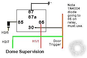
H2/7 Will need a relay See dia. 1.
H2/12, not used.
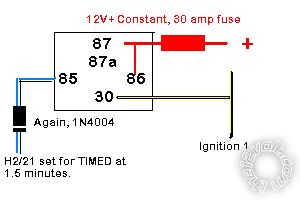
H2/21 Will need a relay. See dia. 2.
You are going to give yourself a world of grief with all those sensors interfering with each other, frankly in the real world all you need is a 508d. Cut both loops on the 507M.
dia._1.bmp
dia._2.bmp------------- Amateurs assume, don't test and have problems; pros test first. I am not a free install service.
Read the installation manual, do a search here or online for your vehicle wiring before posting.
Posted By: veiloctane
Date Posted: February 13, 2012 at 1:34 PM
question about dia.2 for the turbo timer setup
I do not see a connection for #87
is 87 +12V constant as well?
#85 - H2/21 DIODE on ALARM SIDE
#30 - IGNITION 1
#86 - CONSTANT +12V
#87 -
Posted By: howie ll
Date Posted: February 13, 2012 at 1:38 PM
Bad drawing it's definitely connected.
In both diagrams 87a isn't connected.
-------------
Amateurs assume, don't test and have problems; pros test first. I am not a free install service.
Read the installation manual, do a search here or online for your vehicle wiring before posting.
Posted By: veiloctane
Date Posted: February 13, 2012 at 4:26 PM
so i am planning to try and plug in the 508D red and black to
red 12v constant power
black to h1/6 -ground when armed output
Blue - Sensor port 2
Green - Sensor port 2
do I need a relay because I have a backup battery 520T and a 620V also attached?
H1/6 ORANGE (-) 500mA GROUND WHEN ARMED OUTPUT (-) BLUE OUTPUT TO CONTROL MODULE DEI BACKUP BATTERY 520T; (-) BLACK 620V VIPER INDICATOR LIGHT;508d Black
Posted By: howie ll
Date Posted: February 13, 2012 at 4:35 PM
No, that lot is drawing about 2 amps.
-------------
Amateurs assume, don't test and have problems; pros test first. I am not a free install service.
Read the installation manual, do a search here or online for your vehicle wiring before posting.
Posted By: offroadzj
Date Posted: February 13, 2012 at 4:37 PM
Howie, I just wanted to check on one thing regarding your 2nd diagram. The WHITE/ blue is just an activation input on the unit if I'm not mistaking; therefore it would just be connected through a momentary button to a ground source. Then to activate the turbo timer you would simply press the momentary button to activate. Another option would be to just use the remote to activate the turbo timer mode and the WHITE/ blue connection would not be required. The turbo timer run time is set in the programming menu.
This is all assuming this is a DEI unit.. which it appears to be by the wire coloring...
-------------
Kenny
Owner / Technician
KKD Garage LLC
Albany, NY 12205
Posted By: howie ll
Date Posted: February 13, 2012 at 4:39 PM
Quite right Kenny, my only excuse is we have never had any 59XX series here.
-------------
Amateurs assume, don't test and have problems; pros test first. I am not a free install service.
Read the installation manual, do a search here or online for your vehicle wiring before posting.
Posted By: veiloctane
Date Posted: February 13, 2012 at 5:00 PM
ok great so no needed to hookup to the blue/white wire for turbo timer.
does this mean that I can program the 5904 to always turbo time when the ignition is off??
I have a bitwriter 2.7 so I have access to the additional settings.
I am also putting in a push-to-start from advanced keys and both the viper 5904 and advanced keys module use the tachometer and (+)break sense and (-) ebrake/neutral do I need to isolate these wires with a diode?
Manual to the standalone push-start-button is here
https://advancedkeys.com/docs/AK-PSB05.pdf
I also want to enable the push-to-start module when the viper is disarmed.
so i am thinking of using one of the aux ports on the viper default timed 30second to the "push-to-start enable" (purple wire (-) input) on the ak-psb05.
Posted By: offroadzj
Date Posted: February 13, 2012 at 5:27 PM
I believe its just a typo in your post, but its the WHITE/ blue wire you do not need. The blue/white is the defrost output which also is not needed if you do not wish to have your rear defrost come on with the remote starter.
As far as I know (and I can be wrong; I'm not 100% familiar with the newer DEI units), there is no option to automatically run the turbo timer. I believe that you have to activate it either by remote or by the momentary push button. On my car, I chose to use the activation input and then used a factory intercooler sprayer button (factory momentary contact button) to activate the turbo timer so that it remained factory appearing. Its a lot easier than dealing with the remote.
From what I can tell, they appear to be input signals for both units. It would not hurt to diode isolate the signals, but it should not be required. As far as the push start ignition, are you completely eliminating a need for a key in the vehicle or will you still need to use it for the steering wheel lock (if applicable). If the key is still required in the ignition then the push button starter is not needed. A simple ground signal on the WHITE/ blue activation input will do everything that the push to start system is doing.
As far as the push to start enable wire (purple), how I understand the module is that this requires a CONSTANT ground signal to maintain the push to start module functionality. The vehicle should remote start without this wire connected. If you want the remote start to activate and provide the ground to allow the push to start module to operate then you will have to use a latching relay setup (momentary/pulse input to constant signal) that will maintain the ground signal to the module. See Here------------- Kenny
Owner / Technician
KKD Garage LLC
Albany, NY 12205
Posted By: offroadzj
Date Posted: February 13, 2012 at 5:34 PM
Another option you have for the ground signal when the viper is disarmed is to connect the activation wire of the PTS module through a relay to a chassis ground, and use the Viper ground when armed to open/disconnect the relay. The downside to this is that every time the vehicle is armed the relay will be drawing power (minimal draw, but a draw none the less). So if you leave the vehicle armed for a long period of time it could drain the battery. Also, if you ever left the viper disarmed, anybody could simply get in your car and activate the ignition and drive away. Your best bet will probably be to pick up the dedicated key module that goes with that PTS system for the best protection.
-------------
Kenny
Owner / Technician
KKD Garage LLC
Albany, NY 12205
Posted By: howie ll
Date Posted: February 13, 2012 at 5:35 PM
Kenny is right on both counts, use any aux to 85 on diagram 2, set up as timed for 1.5 minutes. Activate that aux before turning off the ignition.
On the second topic Kenny's point about a momentary switch to the white blue is spot on. Will save you the cost and time installing the push start.
KISS which is probably an oxymoron with ref. to this thread.
-------------
Amateurs assume, don't test and have problems; pros test first. I am not a free install service.
Read the installation manual, do a search here or online for your vehicle wiring before posting.
Posted By: howie ll
Date Posted: February 13, 2012 at 5:38 PM
7 to 10 hrs. at 1.3 amps (coil load) to flatten the battery.
-------------
Amateurs assume, don't test and have problems; pros test first. I am not a free install service.
Read the installation manual, do a search here or online for your vehicle wiring before posting.
Posted By: offroadzj
Date Posted: February 13, 2012 at 5:50 PM
Wow... I was never aware how much amperage a relay pulled (never really measured it). I was thinking milliamps... not amps. haha. Yea, I wouldn't suggest going that route.
-------------
Kenny
Owner / Technician
KKD Garage LLC
Albany, NY 12205
Posted By: veiloctane
Date Posted: February 13, 2012 at 11:00 PM
So the reason why im converting to push to start is
is because my ignition and door lock cylinders is busted as the truck was stolen there is no ignition steering wheel lock anymore
I have asked advancedkeys how they did it because there is a video on youtube of a scion that had a viper 5902 and the pushtostart
youtube video link:
https://www.youtube.com/watch?v=ADWWpuIRMno
i also sent a email to advanced keys to see if i need a relay to hook up the aux port from the viper to the advanced keys and here is there reply:
"You can directly connect to Vipers (-) aux output and you also need to change Jump JP2 to Ground Enable type and reboot power to the controller to take effect. After which you should be able to see the Amber light on the Push-Start button whenever Viper aux supply the ground signal to it."
i am thinking of wiring both of these modules together making one harness to tap in to the rest of the trucks wiring.
Posted By: offroadzj
Date Posted: February 14, 2012 at 5:48 AM
Ok, so going by their response, it seems like the ground is only required to activate the ignition and then once activated, the ground can go away... but I would verify that with them just to be 100% sure. You don't want to get a mile from your house and all of a sudden have the ignition shut down because the ground was lost.
-------------
Kenny
Owner / Technician
KKD Garage LLC
Albany, NY 12205
Posted By: veiloctane
Date Posted: February 16, 2012 at 4:03 PM
Just in the process of putting my wiring harness together. and I have a few more questions.
is there a specific manual for the 5904 that tells what each wire does?
what are the best practices for diode usages how do you know when to use a diode???
I have been using the manual for the 5901 from the downloads selection only for the wire descriptions but since its a different model I just want to make sure I am not missing anything.
wires I am not hooking up.
H1/4 WHITE/ BROWN PARKING LIGHT ISOLATION WIRE - PIN 87a of onboard relay unknown/unused
H2/1 PINK/WHITE (-) 200mA IGNITION/FLEX RELAY CONTROL OUTPUT unknown/unused Not used
H2/4 GREEN/ BLACK (-) 200mA OEM ALARM DISARM OUTPUT no factory alarm Not used
H2/9 DARK BLUE (-) 200mA STATUS OUTPUT unknown/unused
H2/10 PINK (-) 200mA IGNITION 1 OUTPUT unknown/unused
H2/18 VIOLET / YELLOW (-) 200mA STARTER OUTPUT unknown/unused
H2/22 ORANGE (-) 200mA ACCESSORY OUTPUT unknown/unused
H2/24 GREEN / WHITE (-) 200mA OEM ALARM ARM OUTPUT no factory alarm no factory alarm not used
H3/8 PINK/BLACK (87a) FLEX RELAY INPUT (key side of ign, acc or starter wire if needed) unknown/unused
Posted By: howie ll
Date Posted: February 16, 2012 at 4:12 PM
First there should be an installation guide with your unit, if not or you purchased from fleabay good luck.
Think of a diode as a stop valve, in this case current flow, generally any device incorporating relays or a relay trigger such as lock, the feed wire should have a diode inserted to block feedback from the relay coil.
Neg outputs from the 5904 should have band towards the alarm.
Also look at the diode section on this site.
-------------
Amateurs assume, don't test and have problems; pros test first. I am not a free install service.
Read the installation manual, do a search here or online for your vehicle wiring before posting.
Posted By: veiloctane
Date Posted: March 12, 2012 at 10:33 PM
help programing the tachometer..
T tried following these instructions in the manual and I cannot seem to get a status light light after 3 seconds.. i have verified the tachometer wire using a voltmeter AC and I am reading 0.3 to 0.35 ~ volts AC.
Here are the steps I tried to follow below
To learn the tach signal:
1. Start the vehicle with the key. Within 5 seconds, press and hold the Control button.
2. After 3 seconds the status LED on your Control Center lights constant when the tach signal is learned.
3. Release the Control button.
Note: When the tachometer is programmed, the main unit automatically enters the Tachometer engine
checking mode.
Since this unit has the capability to learn the tachometer with the analog input or through D2D from an
interface module, the unit gives confirmation as to which source the unit has learned from. After learning the
tach and releasing the Control button, the system:
Flashes the parking lights once if programmed using the analog tach wire.
Flashes the parking lights twice if programmed using the interface module through D2D.
Posted By: veiloctane
Date Posted: April 01, 2012 at 11:52 PM
so i picked up a DEI 454t tach signal generator
i now have the tach signal learned
i am using the orange and green wire on the 454T
my landcruiser starts fine when engine is warm with remote start and with key
i have problems cold starting only with remote start and it seems to under crank when remote starting.
i have tried increasing the Starter Release Fine Tune default from 6 up to 20 and it still under cranks.
what can i do to get a reliable cold remote start??
Posted By: howie ll
Date Posted: April 02, 2012 at 2:08 AM
One or two starter wires?
-------------
Amateurs assume, don't test and have problems; pros test first. I am not a free install service.
Read the installation manual, do a search here or online for your vehicle wiring before posting.
Posted By: veiloctane
Date Posted: April 02, 2012 at 2:13 AM
It has 2 starter wires
And 2 ignitions
I have flex relay set to ign 2
Posted By: howie ll
Date Posted: April 02, 2012 at 2:34 AM
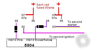
Use this, follow the wiring and use the diodes (1N4004):-
2nd._ignition_and_starter.bmp
Also I suggest relearn tach, this time increase the engine revs to about 1300 when you hit the learn. ------------- Amateurs assume, don't test and have problems; pros test first. I am not a free install service.
Read the installation manual, do a search here or online for your vehicle wiring before posting.
Posted By: veiloctane
Date Posted: April 02, 2012 at 2:56 AM
Ok so i neen 2 more relays and 2 more diodes
If im guessing correctly starter3 and ign2 are not getteng enfough power
I have been using the bitewriter for most of the programing
But there is a nother option thats not avaiable in the bitwriters options
Under menu 3 - 14 "tach mode starter release"
Options are:
Normal
Increase
Decrease
Should i bother playing with those setting? Or is it the same as the 0-20 crank time ajustment ob the bitwriter?
Posted By: howie ll
Date Posted: April 02, 2012 at 3:01 AM
Sorry, flex relay can only handle EITHER one or the other so you will still need a relay and diode.
What starter 3?
Ignore the bitwriter and do as I said, as a a last resort if the other suggested remedies fail increase the revs on programming.
You must have a separate relay (either flex or internal) for each extra ignition and or starter wire.
-------------
Amateurs assume, don't test and have problems; pros test first. I am not a free install service.
Read the installation manual, do a search here or online for your vehicle wiring before posting.
Posted By: veiloctane
Date Posted: April 02, 2012 at 3:20 AM
Sorry starter 3 is a typo.
Ok thanks for clearing that up. It makes sence now
Posted By: kreg357
Date Posted: April 02, 2012 at 6:26 AM
A couple of thoughts...
Any chance the "Diesel Wait to Start" function isn't working properly? Just a
thought being as it starts OK when warm. Maybe as a test, you could switch to a
a fixed delay of 15 or even 30 seconds and see if it remote starts when cold.
Remote Start, (H3) 10-pin connector
H3/1 PINK(+) IGNITION 1 INPUT/OUTPUT BLACK / YELLOW (+) IGN1 @ IGNITION SWITCH HARNESS
H3/2 RED / WHITE FLEX RELAY +12V INPUT Black (+) +12V @ IGNITION SWITCH HARNESS
H3/3 ORANGE(+) ACCESSORY OUTPUT BLUE/RED (+) ACC @ IGNITION SWITCH HARNESS
H3/4 VIOLET(+) STARTER OUTPUT (CAR SIDE) BLACK/ WHITE (+) Starter @ IGNITION SWITCH HARNESS
H3/5 GREEN(+) STARTER INPUT (KEY SIDE) BLACK/ WHITE (+) Starter @ IGNITION SWITCH HARNESS
H3/6 RED IGNITION 1 +12V INPUT (30A FUSED) WHITE/ Red (+) +12V @ IGNITION SWITCH HARNESS
H3/7 PINK/WHITE FLEX RELAY OUTPUT Set to IGN2 blk/grn or blk/red IGN2 @ IGNITION SWITCH HARNESS
H3/8 PINK/BLACK FLEX RELAY INPUT unused
H3/9 RED / BLACK ACC/STARTER RELAY +12V INPUT BLACK (+) +12V @ IGNITION SWITCH HARNESS
H3/10 NC No Connection
If the vehicle does have a Starter2 wire, the easiest way to wire that using one 30/40A SPDT relay below:
Relay Pin 85 to Viper H2/18 (-)200ma Starter Output Violet / YELLOW
Relay Pins 86 and 87 to +12V constant (WHITE/ Red) thru 20 or 30 Amp fuse
Relay Pin 30 to vehicle Starter2 wire
------------- Soldering is fun!
Posted By: howie ll
Date Posted: April 02, 2012 at 8:08 AM
I believe I suggested diesel setting when the OP was asking about WTS wire, quite a while back, also the OP has a bitwriter though I've already suggested he doesn't use for all the obvious reasons.
The main being that most people make small errors when they use these systems for the first time. Instead of going back on what they've done they panic and compound the errors. I'm very much against newbies using software loaders. The UK version of the bitwriter wouldn't even work until the ignition was on, who had to work that one out?
-------------
Amateurs assume, don't test and have problems; pros test first. I am not a free install service.
Read the installation manual, do a search here or online for your vehicle wiring before posting.
Posted By: veiloctane
Date Posted: April 02, 2012 at 11:13 AM
I have. Checked the wait to start
The glow plug wire works
As soon as the light goes out the starter engages
Flex relay already set to ign2
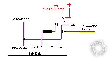
I need to get a second relay for start2
Posted By: howie ll
Date Posted: April 02, 2012 at 12:04 PM
You're quite correct, use this set-up for the second starter relay:-
2nd._starter.bmp------------- Amateurs assume, don't test and have problems; pros test first. I am not a free install service.
Read the installation manual, do a search here or online for your vehicle wiring before posting.
Posted By: veiloctane
Date Posted: April 02, 2012 at 2:13 PM
Relay is hooked up and tried Re programing the tach. Having the same problem should i try different wires on the 454t
Orange / YELLOW?
ORANGE / white?
Posted By: howie ll
Date Posted: April 02, 2012 at 3:11 PM
Try increaseing the revs and reprograming.
-------------
Amateurs assume, don't test and have problems; pros test first. I am not a free install service.
Read the installation manual, do a search here or online for your vehicle wiring before posting.
Posted By: veiloctane
Date Posted: April 05, 2012 at 12:56 AM
my truck currently idles around 600 rpm
i have tried to re-learn the tach at around 1300 rpm and the truck still will not start when it is cold...
however if i change it to timed mode truck will start at 0.8 seconds..
im not sure what else i can do unless to try relearning at even higher rpms 1400 to 2000 rpm??
Posted By: howie ll
Date Posted: April 05, 2012 at 3:48 AM
Did you say you had a Bitwriter, disconnect the glow plug and make wait to start 5 seconds at least, wire that relay as I showed you or all bets are off, leave the crank at 0.8 seconds and the revs at 1200+, also renew your batteries and take into account the age of the vehicle.
-------------
Amateurs assume, don't test and have problems; pros test first. I am not a free install service.
Read the installation manual, do a search here or online for your vehicle wiring before posting.
Posted By: veiloctane
Date Posted: April 05, 2012 at 3:23 PM
yes I do have a bitwriter.
and the relay is hooked up according to the diagram you sent me.
the tach is learned at around 1200-1300 rpm
the crank time feature only works if the engine checking mode is set to off..
if the engine check mode is set to "Tach" the timed changing the crank time does nothing..
I just replaced the batteries in the truck... I know the truck is old 1991 but it starts fine with the key.
i tried virtual tach but it will not stay running
seems like only timed mode works.
|