aftermarket unlock/lock switch wiring he
Printed From: the12volt.com
Forum Name: Car Security and Convenience
Forum Discription: Car Alarms, Keyless Entries, Remote Starters, Immobilizer Bypasses, Sensors, Door Locks, Window Modules, Heated Mirrors, Heated Seats, etc.
URL: https://www.the12volt.com/installbay/forum_posts.asp?tid=131578
Printed Date: April 07, 2026 at 10:53 AM
Topic: aftermarket unlock/lock switch wiring he
Posted By: deeryders
Subject: aftermarket unlock/lock switch wiring he
Date Posted: June 10, 2012 at 1:23 PM
So I hooked up a viper 5901 into my cousins 95 civic 4 door. No power windows no power locks. I put 4 Dei door actuators and wired them through a 451m to the 5901. It works perfectly. He ordered an aftermarket lock and unlock switch which have 5 pins in the back. Pin one is motor pull Pin two is ground Pin three is power Pin 4 is ground and Pin 5 is motor push. Seemed simple enough. I hooked it up and the motor push and pull wires are reading a constant ground and when the switch is depressed it cuts out all power and ground to that particular wire. If I run it to he 451m wires I need the wires to reas about a 7.2 volts when theater particular button is depressed if I run it to the brain wire I need it to read a ground when that particular part of the switch is depressed. However the switch cut out all power when the button is depressed for that wire (ex. Would read a constant ground and when hit unlock the unlock wire on the switch would read nothing until you take your fingure off the switch)How would I wire this switch up to get it to work I'm confused. Thanks guys.
-------------
MECP Certified
Dont Ground Out!!!
Replies:
Posted By: howie ll
Date Posted: June 10, 2012 at 1:32 PM
Go to the thin green and orange wires on the 5901 side of the 451.
Wire as follows:-
Green to pin 2 (lock)
Ground to pin 3
Blue to pin 5 (unlock)
Job done.
-------------
Amateurs assume, don't test and have problems; pros test first. I am not a free install service.
Read the installation manual, do a search here or online for your vehicle wiring before posting.
Posted By: deeryders
Date Posted: June 10, 2012 at 3:00 PM
It didn't work ... I hooked up pin 2 and 4 to ground and it still reads a constant ground and when the switch is depressed it reads nothing .. this is weird
-------------
MECP Certified
Dont Ground Out!!!
Posted By: howie ll
Date Posted: June 10, 2012 at 4:18 PM
Did you not read what I posted, follow what I said.
-------------
Amateurs assume, don't test and have problems; pros test first. I am not a free install service.
Read the installation manual, do a search here or online for your vehicle wiring before posting.
Posted By: howie ll
Date Posted: June 10, 2012 at 4:27 PM
By the way I could alarm and R/S the BMW in my sleep, I've done so many!
-------------
Amateurs assume, don't test and have problems; pros test first. I am not a free install service.
Read the installation manual, do a search here or online for your vehicle wiring before posting.
Posted By: deeryders
Date Posted: June 10, 2012 at 4:47 PM
Yea I did what you said and I also did the way I posted before none of them work
-------------
MECP Certified
Dont Ground Out!!!
Posted By: howie ll
Date Posted: June 10, 2012 at 5:24 PM
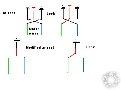
All you needed to do assuming that switch was a momentary 2 pole changeover was to convert it to grounding. Remember on those switches the grounds at rest are always connected to the outputs, hence ground the POWER input which isn't connectred.
If you apply a ground to the INPUT side of the 451, the thin green and blue, one at a time you will lock and unlock the vehicle that's what reconfiguring the switch emulates.
This is so basic how did you ever get to be a lead installer.
The following diagram shows you original configuration and an example then modified and an example:- 5C1_switch.bmp------------- Amateurs assume, don't test and have problems; pros test first. I am not a free install service.
Read the installation manual, do a search here or online for your vehicle wiring before posting.
Posted By: deeryders
Date Posted: June 10, 2012 at 7:42 PM
I totally understand that before the relay you get the ground singnal. Do not question my work ethics. Your not clearly understanding what I'm saying about the switch. The out output wires for the switch read a constant ground at all times. When the switch is depressed that certain line that was reading a constant ground wire reads nothing. I just needed advice soon so I can get it done but if cannot help and have nothing nice to say don't bother posting anything. If you can't help me I will just sit down and I will get it. Thanks.
-------------
MECP Certified
Dont Ground Out!!!
Posted By: howie ll
Date Posted: June 11, 2012 at 4:46 AM
You just don't understand, did you read the diagrams I posted? Of course the outputs are grounded at rest this is equivalent to type one electric windows as on a 530t.
Don't connect the grounds, connect 1 x ground to the power input and the the "outputs" go back to the thin input wires of the 451.
How much simpler can this be?
I'm not questioning your work ethic, I'm questioning your basic lack of electrical knowledge and why you can't make such a simple thing work.
All the switch is doing is sitting parallel to the 451 inputs and emulating the alarm.
Which is effectively the same as controlling type "A" central locking.
-------------
Amateurs assume, don't test and have problems; pros test first. I am not a free install service.
Read the installation manual, do a search here or online for your vehicle wiring before posting.
Posted By: howie ll
Date Posted: June 11, 2012 at 5:00 AM
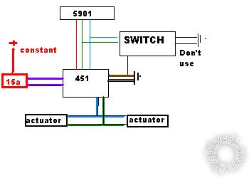
Here is a layout, perhaps this might help:-
36F_untitled.bmp------------- Amateurs assume, don't test and have problems; pros test first. I am not a free install service.
Read the installation manual, do a search here or online for your vehicle wiring before posting.
|