02 Pontiac Grand Prix, Viper 5704
Printed From: the12volt.com
Forum Name: Car Security and Convenience
Forum Discription: Car Alarms, Keyless Entries, Remote Starters, Immobilizer Bypasses, Sensors, Door Locks, Window Modules, Heated Mirrors, Heated Seats, etc.
URL: https://www.the12volt.com/installbay/forum_posts.asp?tid=131898
Printed Date: May 03, 2026 at 12:05 PM
Topic: 02 Pontiac Grand Prix, Viper 5704
Posted By: alexp1289
Subject: 02 Pontiac Grand Prix, Viper 5704
Date Posted: July 28, 2012 at 6:42 PM
Hey guys I'm new here and have just purchased a viper 5704 alarm with remote start. I also go the bypass module Xpresskit xk05, I did a lot of research before coming here and buying my alarm. Can someone just double check for me that I got a compatible bypass module? It says in the xk05 website that my car is compatible with v1.00 firmware. I got the bypass module and alarm on eBay. The bypass module says it shipped with the latest firmware which I suppose builds off of the firmware versions before it so there should be no need to flash the old version? Correct?
Replies:
Posted By: kreg357
Date Posted: July 28, 2012 at 7:10 PM
The XK05 bypass module can be flashed with many ( 11 ) different firmware "flavors" to support many different vehicle applications. Your '02 GP needs PKG3 firmware and the current version is V1.0. The XK05 box and module should have a sticker that shows the firmware that was factory loaded. Any one with internet access and the XKLoader USB cable can change that. The only way to know or sure exactly which firmware / version that is currently loaded is to use the XKLoader cable and check. Here is a link for more info and the install guides for the XK05 : https://www.xpresskit.com/product.aspx?productid=346------------- Soldering is fun!
Posted By: alexp1289
Date Posted: July 28, 2012 at 7:20 PM
I got xkloader2 usb, off eBay that's all they had. That will work just fine to flash my firmware, right?
Posted By: kreg357
Date Posted: July 28, 2012 at 7:27 PM
Absolutely. The XKLoader2 cable is the newer version that will handle the new DB-ALL module plus all the older modules. BTW, good decision to get the XKLoader cable. 
Here is a link to DEI to download the software to support the XKLoader2 : https://www.xpresskit.com/XpressVIP4.aspx The firmware selection and flash process is pretty straight forward. You can change / update the module firmware as often as you wish. ------------- Soldering is fun!
Posted By: alexp1289
Date Posted: July 28, 2012 at 7:42 PM
okay 1 more question about the bypass module. I've heard that if it's hooked up incorrectly on some vehicles it will trip the service anti theft system error code if you hook it up to the wrong wire. I'm not sure which wire it is on my car but is there a correct and incorrect wire to prevent this code from popping up on my dashboard? also I have not been able to find any good wiring diagrams for the viper 5704 alarm system and remote start. I found a good wiring diagram for my car, just have not found a good diagram for the alarm itself. that way I could match everything up before I do the install. And hopefully this will help others in the future :-)
Posted By: kreg357
Date Posted: July 28, 2012 at 8:33 PM
The XK05 w/PKG3 firmware install guide has a good diagram of the wires
and connections required. The PK3 connector at the ignition switch should
be no problem to locate and the guide lists all the wires on that connector.
You should have no problems if you follow that diagram exactly and solder /
insulate all the connections properly.
The Viper 5704 should have come with a Quick Reference Guide. The complete
install guide is only distributed to authorized dealers / installers. Check
in the Downloads section for the complete install guide. If you have the
latest 5704 there could be some differences. Typically the wire colors,
name designation and wire function stay the same, just its connector /
pin location might change.
Your plan is excellent. Locate and download several wire guide lists from
all available sources. Compare them to be ready for any conflicting info.
Preparation is the key to a successful installation. Make up a chart with
the Viper to vehicle, Viper to XK05 bypass and XK05 bypass to vehicle connections
listed. You can post it here for a check by other forum members and get
some good input / feedback and possibly some tips form prior experience.
During the actual install, verify all wires with a Digital Multi Meter prior
to soldering and making the connection. ( With the exception of the Blue PK3
Data wire.)
You will need 2 diodes to connect the alarm to the door triggers and possibly
a relay for the trunk release ( the Vipers Trunk Release output is (-) ).
Here is a note from DEI concerning the trunk release :
On vehicles with keyless entry, can also use brown (-) at the trunk release
relay to the left of the steering column.
------------- Soldering is fun!
Posted By: alexp1289
Date Posted: July 28, 2012 at 8:48 PM
Could someone post the type of diodes that I will need and the relay I will need? And possibly how I will have to hook them up?
Posted By: kreg357
Date Posted: July 28, 2012 at 9:21 PM
The diodes are standard blocking diodes, like the 1N4004 that should be
available at RadioShack. Here is a link to the diode isolation diagrams :
https://www.the12volt.com/diodes/diodes.asp The diagram on the left is
correct for your application with negative door triggers. Bulldog
Security also has a door trigger isolation diagram that is for 4 doors :
https://www.bulldogsecurity.com/diagrams/extrainfo/diagrams/14301_GRAND-PRIX_(-)%20NEGATIVE%20DOOR%20PIN%20ISOLATION%20CIRCUIT.pdf
If you use the Vipers (-) 200mA Trunk Release output for the G.P.'s
(+) BLACK/ White wire at the trunk release switch, use a standard 30/40A
SPDT Bosch style relay. All the relay is doing is converting the Vipers
(-) output to a (+) output the G.P. needs. Here is a diagram :
https://www.the12volt.com/relays/page1.asp#n2p Both diagrams are the same
but the lower one is more appropriately labeled for your application. Fuse
at 10 Amps.
As you can see, most all the information you need is readily available on
this site, with the various wiring guides or via an internet search. ------------- Soldering is fun!
Posted By: howie ll
Date Posted: July 29, 2012 at 1:33 AM
KM, I couldn't make the Bulldog link, is that that a multi diode sleep circuit configuration, if so Ford DEI 1076 in the Downloads/Manuals section above will show it.
Also a comment as if I would, even the installer guides for the new ranges are woefully inadequate, they don't have the typos and wrongly listed wires, they just don't explain what things are for!
-------------
Amateurs assume, don't test and have problems; pros test first. I am not a free install service.
Read the installation manual, do a search here or online for your vehicle wiring before posting.
Posted By: kreg357
Date Posted: July 29, 2012 at 5:07 AM
Hi, Howard! Thanks for catching the link problem. It was just the standard (-)
door pin isolation diagram but for 4 doors instead of just 2 doors. The OP's
G.P. only has 2 doors anyway but it was a part of Bulldogs wire guide for the
G.P. This is a link to Bulldog Security where you can look up the G.P. and view
that door pin isolation link and all their wire info :
https://www.bulldogsecurity.com/bdnew/vehiclewiringdiagrams.asp
I concur on you views about the newer DEI / Viper Install Guides. They are
very brief and do not give any explanations. Think I recently recommended
to another member to download the older guides for a more detailed description
of wire functions and programming options ( 5901 vs 5904, etc ).
------------- Soldering is fun!
Posted By: howie ll
Date Posted: July 29, 2012 at 5:14 AM
The problem there Kregg is that some of the wires have different functions, second unlock on 5901, gone by 5904.
I think your new name might well have to be either Kregg.22 or Kregg Airsoft.  ------------- Amateurs assume, don't test and have problems; pros test first. I am not a free install service.
Read the installation manual, do a search here or online for your vehicle wiring before posting.
Posted By: alexp1289
Date Posted: July 29, 2012 at 5:42 AM
Actually my grand prix is a 4 door. Hopefully these directions are for a 4 door and not just a 2 door.
Posted By: howie ll
Date Posted: July 29, 2012 at 6:01 AM
None, except double the connections and diodes.
-------------
Amateurs assume, don't test and have problems; pros test first. I am not a free install service.
Read the installation manual, do a search here or online for your vehicle wiring before posting.
Posted By: alexp1289
Date Posted: July 29, 2012 at 6:01 AM
Also I wanted to get a little electrical tester. But my question is do I need a continuity tester or circuit tester. it was in 1 of the bulldog videos it lights up when you have the right wire or something like that.
Posted By: howie ll
Date Posted: July 29, 2012 at 6:27 AM
Get a DMM with a 10 or 20 amp AC current tester.
A bulb tester would be dangerous for someone who like yourself isn't sure.
No insults intended but your questions bear out your levels of experience/skill.
You shouldn't even consider attempting a job like this with at least the following:=
Soldering iron
solder
heat shrink sleeving
required extra cable
diodes
relays
insulated tape AND Scotch 33+ for the solder joints you can't sleeve
DMM from Sears, Radio shack.
Philips screwdriver
1/4" socket set 6-13mm
side cutters quality crimper (not $3 in Walmart)
strippers
Stanley knife
cordless drill driver and 2.5mm and 7mm bits (3/16" and 9/32")
assorted size Philips and Torx bits for above
I wouldn't even consider making a joint without first testing.
-------------
Amateurs assume, don't test and have problems; pros test first. I am not a free install service.
Read the installation manual, do a search here or online for your vehicle wiring before posting.
Posted By: alexp1289
Date Posted: July 29, 2012 at 6:43 AM
Are there digital multimeters that I can poke the wires with instead of having to strip it? And by the way I have wired a car radio before.
Posted By: kreg357
Date Posted: July 29, 2012 at 6:50 AM
A good quality DMM and a set of "Bed of Nails" test leads will work well. Search on "Bed of Nails" for pictures of these leads.
You have chosen a very sophisticated alarm system to install. It will require a lot of research, reading and learning to install properly. It will provide an excellent learning experience. ------------- Soldering is fun!
Posted By: howie ll
Date Posted: July 29, 2012 at 7:50 AM
Craftsman at Sears, DMM 0348234400 about $32, "bed of nails" alligator clips (or croc in the UK) about $20, but go to a Sears and look around.
Solder
Portasol by Weller about $90 Irish and I never liked them especially when they used to be sold by Snap-On, Bluepoint badged for about $150 or for a one-off, Portasol mini for under $16.
I personally use Weller Pyropen and Pyropen Jnr., but the US price is believe it or not 50% more than the UK!!
Craftsman lists them as about $140 and $170, the UK prices are $90 and $110.
-------------
Amateurs assume, don't test and have problems; pros test first. I am not a free install service.
Read the installation manual, do a search here or online for your vehicle wiring before posting.
Posted By: alexp1289
Date Posted: July 29, 2012 at 8:14 AM
I got the bed of nails test lead adapters and going to borrow my dads dmm. And I already have a Weller soldering gun and shrink tubing and wire strippers. Anything else I'm missing?
Posted By: howie ll
Date Posted: July 29, 2012 at 8:39 AM
No you're basically there, other tools:=
Trim poppers if you have to remove trims.
"Bojo" plastic trim tools.
T20 Torx bits.
Ref the Weller prices:-
STA-1 (Now WP60) $80.
Junior $72.
-------------
Amateurs assume, don't test and have problems; pros test first. I am not a free install service.
Read the installation manual, do a search here or online for your vehicle wiring before posting.
Posted By: kreg357
Date Posted: July 29, 2012 at 10:58 AM
Looks like only two diodes for the door triggers on the 4 door sedan, as per this note from DEI :
The tan is located in the drivers kick and catches only the drivers door. The dark/blue is located in the passenger kick panel and
catches all other doors, must diode isolate these wires.
------------- Soldering is fun!
Posted By: alexp1289
Date Posted: August 01, 2012 at 3:23 PM
ok so i am trying to flash the 1.00 firmware and Optimax Flash doesnt see my bypass module 0_0 wth????? Any help would be great :) It does say usb device found but thats all it says :(
Posted By: kreg357
Date Posted: August 01, 2012 at 5:59 PM
Not sure where you are at on this. The Optimax section is only for bypass modules that DEI OEM's from Fortin, like the PKALL
and DLPK. The XK0x series are standard DEI modules. With the XKLoader plugged in, try going to this URL : https://www.xpresskit.com/
At that point, select your vehicle from the pull down menus.
That should give you this screen :
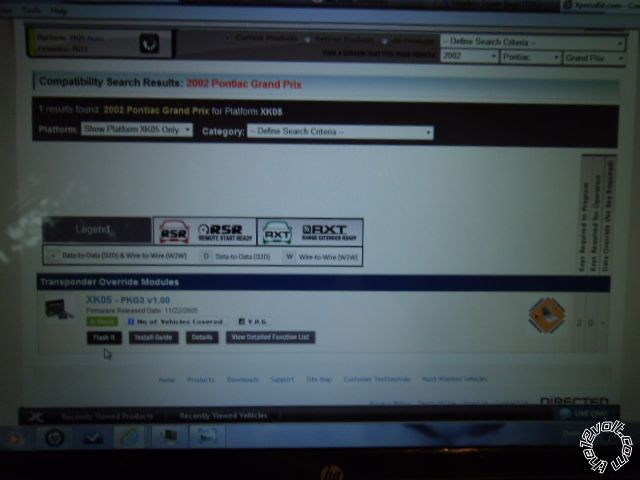
Notice that the box in the upper left area ID's your bypass module. Click on "Flash It" in the lower left area. That should give you this screen :
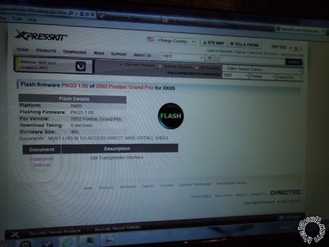
You will need to have previously downloaded some S/W and drivers from DEI to get these screens. ------------- Soldering is fun!
Posted By: alexp1289
Date Posted: August 21, 2012 at 6:08 PM
Ok guys i need a little help and guidance here. Im making my wiring refrance diagram for the viper remote starter connections. Here is a refrence sheet for my car--- https://www.dropbox.com/s/cg8ui2kx19sahsj/2002%20Grand%20Prix%20Wire%20Diagram.doc
And here is what i have so far for the remote start wires.
REMOTE START 10-PIN HEAVY GUAGE CONNECTOR
Fused Connections-
Red (Ignition Input- 1)
RED / White (Ignition- 2 Flex Relay Input)
RED / Black (Starter Input/Accessory)
Regular Connections-
Pink (Ignition Input/Output- 1)
Orange (Accessory Output)
Green (Starter Input- Key Side Kill)
Violet (Starter Output- Car Side Kill)
Pink/White (Ignition- 2 Flex Relay Output)
Pink/Black (Flex Relay Input Key Side If Required)
The other thing im not sure of is if some of these need to be just need to be tapped into and which ones need to be cut. So that one side can be input from the key side and the other is hooked up to output for car side. Im learning slowly :/
Please help me figure out which wires go where and feel free to edit and add to what i have. Im hoping to have a complete document i can look at while installing. But i need your help :)
Posted By: howie ll
Date Posted: August 21, 2012 at 6:25 PM
Cut the starter wire, key side to green and starter motor side to violet.
All others are soldered, remember pink to ignition 1 and pink/white to ignition 2.
Also 3 ACC wires, orange to ACC 1.
Satellite loom orange low NEG 2nd. ACC output via 2 1N4004 diodes in a "Y" shape to a pair of relays, orange to both 85, 30amps fused to 86 and 87 each relay, then 30 on each relay to ACC 2 and ACC 3.
Absolutely mandatory or you WILL throw a DTC.
When you say "patch" how are you joining the cables?
Over to Kregg, it's 12:30am and I'm off to sleep.
-------------
Amateurs assume, don't test and have problems; pros test first. I am not a free install service.
Read the installation manual, do a search here or online for your vehicle wiring before posting.
Posted By: howie ll
Date Posted: August 21, 2012 at 6:28 PM
Cut the starter wire, key side to green and starter motor side to violet.
All others are soldered, remember pink to ignition 1 and pink/white to ignition 2.
Also 3 ACC wires, orange to ACC 1.
Satellite loom orange low NEG 2nd. ACC output (H2/22) via 2 1N4004 diodes in a "Y" shape to a pair of relays, orange to both 85, 30amps fused to 86 and 87 each relay, then 30 on each relay to ACC 2 and ACC 3.
Absolutely mandatory or you WILL throw a DTC.
When you say "patch" how are you joining the cables?
Over to Kregg, it's 12:30am and I'm off to sleep.
-------------
Amateurs assume, don't test and have problems; pros test first. I am not a free install service.
Read the installation manual, do a search here or online for your vehicle wiring before posting.
Posted By: alexp1289
Date Posted: August 21, 2012 at 6:41 PM
I'm soldering all my connections. When you ask about me patching wires I meant tapping into them because I have a tool that allows me to strip the wire without cutting. The others I have to cut so I have a key side input and a car side output.
Also I have a question about the flex relay wires. Are they needed on my car or not? And if so where do they go and yo what colors? I'm slowly gaining the confidence for the install but I'm doing a lot of asking questions and planning as you can see.
Posted By: kreg357
Date Posted: August 21, 2012 at 7:46 PM
Use a DMM and verify all wires at ignition switch harness.
Constant 12V+ Wire: Red ( and possibly RED / White ) Split load between H3/2, H3/6
Constant 12V+ Wire Location: Ignition Switch Harness and H3/9 ( and H1/2 )
Starter Wire (+): Yellow Cut wire H3/4 car side
Starter Wire Location: Ignition Switch Harness H3/5 key side
Second Starter Wire (+): N/A
Second Start Wire Location: N/A
Ignition Wire (+): Pink H3/1
Ignition Wire Location: Ignition Switch Harness
Second Ignition Wire: White H3/7 Program default = IGN2
Second Ignition Wire Location: Ignition Switch Harness
Accessory Wire: Orange H3/3
Accessory Wire Location: Ignition Switch Harness
Second Accessory Wire: Brown External Relay controlled by
Second Accessory Wire Location: Ignition Switch Harness ORANGE (-) 200mA ACCESSORY OUTPUT
This Brown ACC2 wire might not be
necessary for remote start.
H3/1 PINK (+) IGNITION 1 INPUT/OUTPUT Pink
H3/2 RED / WHITE (+) FUSED (30A) IGNITION 2 / FLEX RELAY INPUT 87 Red
H3/3 ORANGE (+) ACCESSORY OUTPUT Orange
H3/4 VIOLET (+) STARTER OUTPUT (CAR SIDE OF THE STARTER KILL) Yellow
H3/5 GREEN (+) STARTER INPUT (KEY SIDE OF THE STARTER KILL WIRE) Yellow
H3/6 RED (+) FUSED (30A) IGNITION 1 INPUT Red
H3/7 PINK/WHITE (+) IGNITION 2 / FLEX RELAY OUTPUT White
H3/8 PINK/BLACK (+) FLEX RELAY INPUT 87A key side of FLEX RELAY N.U.
H3/9 RED / BLACK (+) FUSED (30A) ACCESSORY/STARTER INPUT Red
H3/10 NC (no connection) NC
ACC2 external relay ( 30/40 Amp SPDT ) if needed :
Relay Pin 85 to ORANGE (-) 200mA ACCESSORY OUTPUT
Relay Pin 86 and 87 to +12V constant fused at 20 Amps
Relay Pin 30 to Brown ACC2 wire
Relay Pin 87A not used - insulate ------------- Soldering is fun!
Posted By: howie ll
Date Posted: August 22, 2012 at 2:53 AM
Now you've had the satellite relay question answered 3 times, once by me before you even posted!
Sorry, I somehow read it as 3 ACC wires not two, scratch the post regarding 2 relays, only one required.
AFIK not connecting BOTH ACC wires will throw trouble codes/transmission problems (DTC s).
-------------
Amateurs assume, don't test and have problems; pros test first. I am not a free install service.
Read the installation manual, do a search here or online for your vehicle wiring before posting.
Posted By: alexp1289
Date Posted: August 22, 2012 at 9:54 AM
What do you guys mean when you say to split the load of the 12v constant wire? Also the reference sheet you posted is a little confusing. Is the left side the wires coming from the viper? And the right side the color of the car wires? Also what do you mean about the satellite relay?
Posted By: howie ll
Date Posted: August 22, 2012 at 11:08 AM
Split load simply means all those wires mentioned H1/2, H3/2, H3/6 and H3/9 all go to a constant source, be it red or red white or if thicker and readily accessible the constant feed to the interior fusebox from the battery.
Join so that all the fuses are intact.
Viper on the left and Pontiac on the right, surely you can see that?
What used to be called "flex relay output" or "satellite relay" is now covered by the 24 pin plug (h/2) and the wire to give you second accessory is the orange at H2/22.
Sorry, Kregg is right the brown 3rd. ACC wire doesn't need to be powered up.
-------------
Amateurs assume, don't test and have problems; pros test first. I am not a free install service.
Read the installation manual, do a search here or online for your vehicle wiring before posting.
Posted By: alexp1289
Date Posted: August 22, 2012 at 1:35 PM
the colors on the left hand side match the diagram I have for my car and the right side seems to match what I have for the Viper.
Posted By: howie ll
Date Posted: August 22, 2012 at 1:50 PM
2 thoughts
a) The left hand side of your screen has a blue border.
b) Do you actually have an installation guide for the 5704?
I GIVE UP.
-------------
Amateurs assume, don't test and have problems; pros test first. I am not a free install service.
Read the installation manual, do a search here or online for your vehicle wiring before posting.
Posted By: alexp1289
Date Posted: August 22, 2012 at 4:10 PM
One problem if the left side is supposed to be the viper then my harness isn't colored right. There is no yellow starter wire on the 10 pin connector, there is however a yellow starter wire for my car. So I'm very confused Howie please don't give up on me :-P
Posted By: howie ll
Date Posted: August 22, 2012 at 4:57 PM
Looking back from your point of view I realise it must be confusing.
Go to the last paragraph before the relay description, work from that with the alarm wires and colours on the left.
As you realised the Pontiac STARTER is yellow.
That one gets cut, key side to green and motor (i.e. away from the switch) to the violet.
The others all get joined.
-------------
Amateurs assume, don't test and have problems; pros test first. I am not a free install service.
Read the installation manual, do a search here or online for your vehicle wiring before posting.
Posted By: alexp1289
Date Posted: August 22, 2012 at 10:56 PM
1 question about the flex relay. Do the wires that come off of the 10 pin connector get rid of the need for the diodes? If not then what do I do with the diodes I'm still having a hard time picturing how they would go together with the wires how I would do that? also does the 24 pin connector use some kind of mechanism to stop the DTC from popping up or are the diodes required for that as well. I'm starting to realize that there's a lot of wires that are going to be connected to the ignition harness is it okay to tap into the ignition wire harness then wrap all the wires on to their connections together and then solder?
Posted By: howie ll
Date Posted: August 23, 2012 at 2:03 AM
The only wire needing a diode is the thin orange at h2/22 for the ACC.
The thick wires won't need diodes just join.
-------------
Amateurs assume, don't test and have problems; pros test first. I am not a free install service.
Read the installation manual, do a search here or online for your vehicle wiring before posting.
Posted By: alexp1289
Date Posted: August 23, 2012 at 12:37 PM
I got a 40 amp single pole double throw relay for the trunk release, that will work just fine right?
Posted By: howie ll
Date Posted: August 23, 2012 at 12:50 PM
Yes.
-------------
Amateurs assume, don't test and have problems; pros test first. I am not a free install service.
Read the installation manual, do a search here or online for your vehicle wiring before posting.
Posted By: alexp1289
Date Posted: August 25, 2012 at 12:31 PM
About how big are the ignition wires typically? Are there any tips that you guys have for making the install it easier? I was thinking maybe removing the front seats. Any other tips you might have that would make life easier that would be cool :-)
Posted By: alexp1289
Date Posted: August 25, 2012 at 1:10 PM
Also does it matter where I hook up the main Power for the alarm? doesn't have to be hooked up directly to the battery or can I choose any 12 volt constant wire? And then ground it to somewhere in the dash? I'm just not sure if or what wires will always be powered on even if the cars not when it's locked. sorry for the simple questions but I just want to make sure I don't make any mistakes the first time.
Posted By: howie ll
Date Posted: August 25, 2012 at 1:39 PM
Red and RED / white at ignition loom, split the load, i.e. 2 to one and 2 to the other.
If you enjoy removing the seats fine, NOT if there are built in air-bags.
-------------
Amateurs assume, don't test and have problems; pros test first. I am not a free install service.
Read the installation manual, do a search here or online for your vehicle wiring before posting.
Posted By: alexp1289
Date Posted: August 26, 2012 at 3:27 PM
Does anybody have a diagram for the satellite relay? And which way do the diodes go?
Posted By: alexp1289
Date Posted: August 26, 2012 at 3:32 PM
The 10 pin connector has a flex relay already on it isn't that the same thing?
Posted By: alexp1289
Date Posted: August 26, 2012 at 4:28 PM
This is all I need help on I need more details.
Posted By: kreg357
Date Posted: August 26, 2012 at 7:28 PM
Not sure what you mean by "satellite relay". If you are referring to the extra relay
for the cars Brown ACC2 wire, it was given previously.
ACC2 external relay ( 30/40 Amp SPDT ) if needed :
Relay Pin 85 to ORANGE (-) 200mA ACCESSORY OUTPUT ( from Viper )
Relay Pin 86 and 87 to +12V constant fused at 20 Amps
Relay Pin 30 to Brown ACC2 wire at Grand Prix Ignition Harness
Relay Pin 87A not used - insulate
The 1N400x diode would be added between Relay Pins 86 and 85 with the band towards Pin 86.
If you are referring to the Vipers Flex relay that will be used for the cars IGN2 wire,
it was included in the previously listed Viper H3 wire connections :
Viper H3 harness wires 2002 Pontiac Grand Prix Ignition Harness
H3/1 PINK (+) IGNITION 1 INPUT/OUTPUT Pink
H3/2 RED / WHITE (+) FUSED (30A) IGN 2 / FLEX RELAY INPUT 87 Red ( or RED / White )
H3/3 ORANGE (+) ACCESSORY OUTPUT Orange
H3/4 VIOLET (+) STARTER OUTPUT (CAR SIDE) Yellow
H3/5 GREEN (+) STARTER INPUT (KEY SIDE) Yellow
H3/6 RED (+) FUSED (30A) IGNITION 1 INPUT Red ( or RED / White )
H3/7 PINK/WHITE (+) IGNITION 2 / FLEX RELAY OUTPUT White
H3/8 PINK/BLACK (+) FLEX RELAY INPUT 87A FLEX RELAY N.U.
H3/9 RED / BLACK (+) FUSED (30A) ACC/STARTER INPUT Red ( or RED / White )
H3/10 NC (no connection) NC
Here is a picture of a generic GM vehicle with similar wires / colors in the ignition harness :
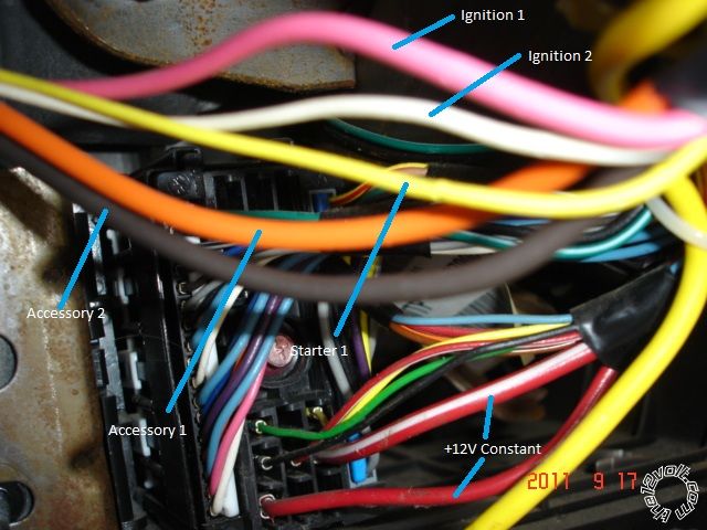
------------- Soldering is fun!
Posted By: alexp1289
Date Posted: August 26, 2012 at 7:31 PM
I thought you said something about using diodes on 1 of the wires or else I will throw transmission trouble codes? that's on trying to figure out is the specific send anything that I can look at to make it easier to understand.
Posted By: kreg357
Date Posted: August 26, 2012 at 7:34 PM
Not sure but I think that info came from Howard.
-------------
Soldering is fun!
Posted By: howie ll
Date Posted: August 27, 2012 at 1:48 AM
I might have had the wrong info, it may have been Ford vans! On my original diagram I showed the diodes in-line with the orange to 85 rather than across the relay coil.
In practise I do both.
-------------
Amateurs assume, don't test and have problems; pros test first. I am not a free install service.
Read the installation manual, do a search here or online for your vehicle wiring before posting.
Posted By: howie ll
Date Posted: August 27, 2012 at 1:50 AM
OP diodes were to quench relay back EMF nothing to do with DTCs.
-------------
Amateurs assume, don't test and have problems; pros test first. I am not a free install service.
Read the installation manual, do a search here or online for your vehicle wiring before posting.
Posted By: alexp1289
Date Posted: August 27, 2012 at 12:14 PM
okay so I took my dash apart underneath and I have good access to the wires. I need some ideas of where to mount the brain of the Viper that will be easy for me to get to but when it's put together won't be easy for a thief to get at. I'm drawing blanks here guys :-\
Posted By: soundnsecurity
Date Posted: August 27, 2012 at 6:30 PM
get creative, i have found all kinds of ways to mount alarm brains. zip tie to a wire harness or in between multiple wire harnesses, screw it to some sort of metal, if you have insulation that goes up almost to the top of the dash you can try stuffing it between the firewall and insulation as a last resort just to hide it. under the carpet, in the kick panel, ive even mounted one under the driver seat before, which is the last place a thief is going to look for an alarm brain, although i dont recommend this way unless you are prepared to extent almost every wire. a thief will always go under the dash first to find the alarm so the farther away you have it from under the dash, the better protected you will ultimately be.
i prefer to use screws if at all possible because it makes it that much harder for a thief to rip it down.
good places to mount the brain are usually high under the dash, in the center console or behind the radio, or behind the instrument cluster is an awesome spot if its not too hard to take the cluster out. its hard to tell you exactly where because im not there to look for a spot myself and i usually go into every car like its a blank slate so i dont bother remembering how things look.
another good tip is to find a spot that makes it easier to run your alarm wires along side factory wire harnesses because this will make it harder to identify the alarm wires and make for a much cleaner install. if you dont take your time and think about where each wire needs to go and run those wires with other harnesses or hidden behind panels, then a thief can just follow those wires back to the alarm. the most important wires to hide are the power, ground, and siren wires.
-------------
Posted By: howie ll
Date Posted: August 28, 2012 at 3:39 AM
Behind dash, glove box, in centre console, behind kick panel if room, under front seats etc. etc. etc. as stated above, your imagination and keeping the high current cables short are your only limitations.
My first choice is behind instrument panel if there's room, easy for you to get at, easier to stealth the wiring, hard for the naughty person to find.
-------------
Amateurs assume, don't test and have problems; pros test first. I am not a free install service.
Read the installation manual, do a search here or online for your vehicle wiring before posting.
Posted By: alexp1289
Date Posted: August 31, 2012 at 10:22 AM
okay so I've ran into 1 more problem which is extending the wires for the really small wires I can't seem to find out what size wire it is so that I can order it on the internet because no store around here seems to carry it so if you guys could help me out with what size wire I need I can order it offline :-) so far all I have is the ignition wire to extend the 10 pin connector for my viper alarm.
Posted By: howie ll
Date Posted: August 31, 2012 at 11:35 AM
Are you for real? Cut about an inch off the wires you want to extend and visit an auto parts store.
You got clever stupid with the location didn't you.
I've been doing alarms since about 1980, apart from a couple of Mercedes and Audis with the locking and door controls in the rear I've NEVER had to extend, every 3 months I throw away a box full!
-------------
Amateurs assume, don't test and have problems; pros test first. I am not a free install service.
Read the installation manual, do a search here or online for your vehicle wiring before posting.
Posted By: howie ll
Date Posted: August 31, 2012 at 11:38 AM
There's another expression here, all the "P"s
P*ss Poor Planning Prevents Proper Performance.
-------------
Amateurs assume, don't test and have problems; pros test first. I am not a free install service.
Read the installation manual, do a search here or online for your vehicle wiring before posting.
Posted By: alexp1289
Date Posted: August 31, 2012 at 11:46 AM
actually I chose to Mountain in the center console because that was the best place but nobody would ever look for it and the easiest if I ever need to work on it or fix something I took extending the wires into consideration so who knows.
Posted By: alexp1289
Date Posted: August 31, 2012 at 12:00 PM
Call me an idiot but I chose the location I saw best. Both reachable for repairs if needed and not in an obvious spot :-P and btw Howie the smallest wire the auto parts stores have and every other store for that matter was 18 awg. So instead of bashing me could you please help me find the correct wire. Most I find online is single strand :-( I need multi strand 24 awg for one of the connections. Your help is greatly appreciated :-P Thanks bro :-D
Posted By: howie ll
Date Posted: August 31, 2012 at 12:00 PM
Extend using the leftovers.
-------------
Amateurs assume, don't test and have problems; pros test first. I am not a free install service.
Read the installation manual, do a search here or online for your vehicle wiring before posting.
Posted By: howie ll
Date Posted: August 31, 2012 at 12:04 PM
Then use 18g, technically better if you have to extend, less voltage drop.
-------------
Amateurs assume, don't test and have problems; pros test first. I am not a free install service.
Read the installation manual, do a search here or online for your vehicle wiring before posting.
Posted By: alexp1289
Date Posted: August 31, 2012 at 12:10 PM
don't you think I would have used the leftovers if I had any? So far I've got a mounting spot for the brain and I tried to see if the wires would reach and they are 2 feet to short. My mounting spot is already set in stone because I already cut And drilled holes for the wires :-)
Posted By: kreg357
Date Posted: September 01, 2012 at 7:55 PM
Locally, you might try a RadioShack. Just make sure the wire is stranded, not single conductor. For a wider selection of colors and gauges you might have to go online. There are many online sources for the wire you seek. Here is one example :
https://www.jameco.com/webapp/wcs/stores/servlet/StoreCatalogDisplay?langId=-1&storeId=10001&catalogId=10001
As Howard mentioned, there will be several wires from the R/S brain that will not be used at all for the install. While the color will be different, you can use them to extend the necessary wires. Just keep track of the wire name and new color to make the connection correctly. If you have a lot of heat shrink tube, solder and time on you hands, you could even lengthen the wire by soldering in the unused, off-color piece in the middle of the short wire. Thereby keeping the correct color at the connection end.
------------- Soldering is fun!
Posted By: howie ll
Date Posted: September 02, 2012 at 12:04 AM
Kregg, you've stolen my thoughts again, that trick you mentioned in the last two sentences or is that just applied common sense?
-------------
Amateurs assume, don't test and have problems; pros test first. I am not a free install service.
Read the installation manual, do a search here or online for your vehicle wiring before posting.
Posted By: alexp1289
Date Posted: September 02, 2012 at 4:07 AM
Howie as we all have figured out is a wise a**. Thanks for graciously giving me your thoughts oh godly one!! And forgive me for not wanting nothing more than to screw up not only my alarm install but investment. Clearly you're both good mods but Howie thinks all of this is just common knowledge. I've always been told check twice solder once. Forgive me for double checking and making sure that my information is correct as I said before quit bashing me. Id expect more from a mod like yourself Howie and remember that as some of us may know what you speak of. Our first install is still a tricky one and a bit nerve racking. You may be an old pro but look at who you're talking with .
Posted By: howie ll
Date Posted: September 02, 2012 at 5:08 AM
Your attitude is quite understandable except for one small point, you don't appear to absorb anything.
You don't appear to have ANY grasp of what you're doing or any ability to plan ahead.
I've "mentored" plenty of newbies here and given praise and congratulations when it's deserved.
Yes my advice is very cynical but let's face it this thread has been well discussed in PMs and others have generally been surprised at my patience with you.
You keep on asking the sort of questions I WOULD'T expect from my 12 and 14 year old grandchildren when I get them to install equipment with me.
My daughter at 14 was pulling apart Toyota interiors, running wiring and installing audio at the local Toyota shop on school holidays.
-------------
Amateurs assume, don't test and have problems; pros test first. I am not a free install service.
Read the installation manual, do a search here or online for your vehicle wiring before posting.
Posted By: howie ll
Date Posted: September 02, 2012 at 5:14 AM
And here's some thinking outside of the box for you, 2 examples;:-
domestic cabling, 6-10 amp capacity (it would be 6 here but we run 230VAC), 3 core multi stranded..Home Depot?
5-7 core cable for towing brackets, any good auto factors.
-------------
Amateurs assume, don't test and have problems; pros test first. I am not a free install service.
Read the installation manual, do a search here or online for your vehicle wiring before posting.
Posted By: alexp1289
Date Posted: September 02, 2012 at 9:05 AM
If I had not planned ahead I surely wouldn't have measured to see if the wires fit and I surely wouldn't have asked your opinion I would have just gone straight to installing so clearly I don't know how to plan ahead? Am I right? All of that aside I do appreciate your help. I have at this point absorbed everything we've talked about :-) But just be forewarned I may have a few more questions because I'm very close to installing. And you would be right that I have 0 experience in car electrical.
Posted By: howie ll
Date Posted: September 02, 2012 at 9:34 AM
As it happens wise**se is incorrect in these circumstances God is nearer the mark and you will probably end up on your knees praying for me to sort out your problems!
Because it's unlikely anyone else well, I haven't a clue what a Pontiac is (Opel/Vauxhall/Holden copies?) can't remember what unit you're fitting, don't care and it doesn't really matter the principles are all the same.
Being anal, just wondering if beforehand you actually thought of laying out the looms, attached to the brain just to see if they would reach?
I seem to remember making the point a few posts ago something to the effect of "shorter the better".
There are technical as well as practical reasons for that comment, again you should have thought "WHY has he said that?"
-------------
Amateurs assume, don't test and have problems; pros test first. I am not a free install service.
Read the installation manual, do a search here or online for your vehicle wiring before posting.
Posted By: howie ll
Date Posted: September 02, 2012 at 9:38 AM
Actually the best positions are 1) behind instrument cluster and 2) behind the glovebox (and airbag).
Harder to get at unless you know where and how to get to them, the average naughty doesn't know how with the siren (and maybe a hidden siren) blaring away.
At least one other experienced professional mentioned that to you again you either weren't listening or chose to ignore it.
-------------
Amateurs assume, don't test and have problems; pros test first. I am not a free install service.
Read the installation manual, do a search here or online for your vehicle wiring before posting.
Posted By: soundnsecurity
Date Posted: September 02, 2012 at 11:19 AM
now now gentlemen, lets play nice. to answer the OP's question, id really doesnt matter what exact gauge wire you use to extend your wire, as long as its close then it will be fine. most of the wires on an alarm carry a small current of less than 1 amp. with that said, because the wires are low current, they shouldnt be super long either because that will cause a voltage drop and things wont act right.
you did good with putting the alarm in the console, i probably would have done the same thing as long as i had the extra time to burn. if i remember correctly the dash of those pontiacs dont come apart, only the under dash can be removed and the upper dash is all one piece. i always hated doing those because it meant that i was gonna spend a lot of time under the dash with the brake pedal stabbing me in my ear. also not much room for hiding anything other than wires and the bypass module.
also just a side note, the people on here help tons and tons of first time installers going through the same thing you are. so we know they we need to spell things out in the simplest possible way, which is what has been done, and it can be frustrating for us because we honestly cant make it any simpler. when every one of our answers leads to six more questions some people can get a little short tempered. case in point, its page 6 and you have yet to connect a single wire. if you think you are having problems now just wait until you are in the middle of the install and get stuck on something and your car is in 20 pieces, undrivable, etc.
my first basic alarm took me 5 hours on an easy easy car with someone standing over me, so trust me when i say i know where you are coming from. so dont expect to finish yours with any kind of speed either
-------------
Posted By: alexp1289
Date Posted: September 02, 2012 at 12:54 PM
only need to extend the wires like 3 feet I should be fine right? probably a little bit less than that but that should be no problem right?
Posted By: soundnsecurity
Date Posted: September 02, 2012 at 1:04 PM
no problems
-------------
Posted By: alexp1289
Date Posted: September 07, 2012 at 11:44 PM
does anybody know what the light flash polarity would be for my car I haven't been able to find that. I just need to know where to put the fuse thats in the brain of the alarm.
Posted By: howie ll
Date Posted: September 08, 2012 at 1:11 AM
Look in the vehicle wiring section here before posting.
-------------
Amateurs assume, don't test and have problems; pros test first. I am not a free install service.
Read the installation manual, do a search here or online for your vehicle wiring before posting.
Posted By: tommy...
Date Posted: September 08, 2012 at 9:47 AM
alexp1289 wrote:
does anybody know what the light flash polarity would be for my car I haven't been able to find that. I just need to know where to put the fuse thats in the brain of the alarm.
Did you check your wiring with a DMM. Do you know how to tell if it is a Positive trigger with your Meter? You are checking the wires before making the connection? Tell us what the DMM did when you checked the wire... Or look at your tech sheet and see what symbol it gives you, then Test anyway to be sure its correct. Now would probably be a good time to learn these basic fundamentals. Will help on next Install. ------------- M.E.C.P & First-Class
Go slow and drink lots of water...Procrastinators' Unite...Tomorrow!
Posted By: alexp1289
Date Posted: September 08, 2012 at 1:24 PM
Do I test using the wires on my headlight harness? That's what I would think to do. Or can I use the wires on my blinkers? They also flash when I lock the car. Hook the black to the ground on the car and the red to 1 of the wires and look for a spike in the voltage when the lights flash? I'd also look for a +/- sign next to the jumping numbers right? Then I'd know which one it is?
Posted By: kreg357
Date Posted: September 08, 2012 at 1:47 PM
No, you want to test the actual wire you will be connecting the Viper to.
To locate the wire for the parking lights that the Viper connects to, first obtain several
wiring guides. Howard suggested the listing for your car in this sites "Vehicle Wiring" area.
https://www.the12volt.com/installbay/forum_posts.asp~TID~7175 You should also go to the Bulldog site
( https://www.bulldogsecurity.com/bdnew/vehiclewiringdiagrams.asp ) and the Ready Remote site
( https://www.readyremote.com/main.asp ) to download and print their info. For your vehicle, all
three have consistant info as follows :
PARKING LIGHTS ( + ) BROWN (+) @ HEADLIGHT SWITCH
This gives you all you need to locate & verify the correct wire and set the Viper fuse/jumper
properly. At the back of the vehicles Hweadlight switch is a connector with several wires. At
leat one of the them is Brown ( prehaps only one of them is Brown ). Set your Digital Multi
Meter to 20V DC, connect the Black lead to a good chassis ground and the Red lead to the suspect Brown
wire using the "bed-of-nails" test lead. When you turn the Headlight switch to the parking lights
postion the DMM should read +12v. You now have located and verified the correcrt wire that you
will use during the install. ------------- Soldering is fun!
Posted By: howie ll
Date Posted: September 08, 2012 at 2:00 PM
K, don't you hate some keyboards, Hweadlight switch?
My favourite is ANSQWER
I think wqe should either learn to ytpe or slow down!
And no I left the above as it would be before edits.
-------------
Amateurs assume, don't test and have problems; pros test first. I am not a free install service.
Read the installation manual, do a search here or online for your vehicle wiring before posting.
Posted By: kreg357
Date Posted: September 08, 2012 at 2:24 PM
 Somehow I missed that typo and I even run Speckie! Oh, the shame of it... ------------- Soldering is fun!
Posted By: alexp1289
Date Posted: September 18, 2012 at 5:44 PM
Before you guys say anything I'm not done with my install, so don't give me any crap about that. I work a lot so I have done what I can here and there just connecting the wires that won't disable my car :-P I'm very close to being done though so that's a good thing. I have one question about the bypass module. The little wires coming from the ignition is where my bypass module wires get soldered? Correct? It doesn't seem logical that any would go to my thick ignition wires but I just wanted to ask.
Posted By: kreg357
Date Posted: September 18, 2012 at 6:14 PM
Never be in a hurry. "Haste makes waste." You only want to do this project once.
No, none of the Vipers H3 heavy gauge wires go to the PassKey3 connector.
However one of the XK05 wires can go to the H3 harness.
XK05 Destination
Brown GWR Viper Blue (-) 200mA Status Output
Red +12V Constant Viper Red ( or RED / White or RED / Black )
The rest ( Green, Black, Pink, Pink/White ) get connected to the G.P. PassKey3 connector at the ignition switch.
Almost done. 
------------- Soldering is fun!
Posted By: alexp1289
Date Posted: September 18, 2012 at 6:55 PM
I was looking at the viper wires and there names on the sheet that came with the alarm and noticed there's a rear defogger/2nd status (-) 200mA output. Can I connect that to my rear defogger button in the front of my car so my rear window is clear in the winter? If not how do I do that?
Posted By: alexp1289
Date Posted: September 20, 2012 at 5:58 PM
Hey guys I've done some wire testing to verify the correct wires and just wanted to have someone look at my results before I solder.
Light blue- lock wire (stays at zero and jumps when locking with OEM remote and switch) usually jumps to 0.10 but it jumps even when unlocking to 0.07 but never any higher :-\
White unlock wire- always reads 12.22 and drops when unlocking and lock button are pressed.
My dmm is set to 20dcv and black lead into COM and red in V. I'm kinda confused here. Also my trunk BLACK/ white wire reads 12.00 when the button is pressed so I'm almost certain I'm doing this correctly :-(
Posted By: alexp1289
Date Posted: September 20, 2012 at 8:15 PM
Really no one can help?
Posted By: kreg357
Date Posted: September 20, 2012 at 9:04 PM
The correct way to test for your Lock and Unlock wires is as follows:
Set the DMM to 20 VDC. Connect the Red lead to +12V constant and the Black lead to the suspect
wire. When the signal is present ( either lock or unlock ) to DMM will show +12V.
This DMM setup and testing method works on wires that are noted as (-) signals.
On some vehicles you might have to use ( turn ) the key in the door cylinder to obtain the signal
and locate / verify the correct wire.
To locate the Trunk Release wire, which is a (+) signal, set the DMM to 20 VDC, connect the
Black lead to chassis ground and the Red lead to the suspect wire. When the signal is present,
the DMM will show +12V.
This DMM setup and testing method works on wires that are noted as (+) signals. ------------- Soldering is fun!
Posted By: alexp1289
Date Posted: September 20, 2012 at 9:14 PM
Oh ok. I was using the black lead to chassis ground method to find out the right lock wire. Had no idea there was a different way for the lock wire lol.. sry guys (I looked at other threads on here to see if anyone else mentioned the correct way before asking I swear...I kept going wth on the lock wire cause it was reading weird lol). If you guys wouldn't mind, could someone give me a lesson on why there are 2 different testing methods?
Posted By: kreg357
Date Posted: September 20, 2012 at 10:33 PM
There are two different testing set-ups because there are two basic logic levels
used in vehicle circuits that you will be testing / identifying.
Prior to Multi-plex circuits and Data ( CAN Bus ) circuits all cars used the two voltage
levels supplied by the cars battery to control its power accessories. The two levels are
+12V and ground. We can use a very simple Horn circuit as an example ( no power relay ).
Battery power, +12V is run thru a protective fuse and to one side of the horn. The other
side of the horn is wired to the horn button in the steering wheel. The horn button is a
simple momentary contact switch, normally in the OFF or open position. The other side of
the horn switch is wired to chassis ground. When the horn button is depressed, it makes a
connection from the horn thru the switch which is wired to chassis ground. Chassis ground
is the entire metal frame of the vehicle. The negative lead of the battery is connected to
the vehicles frame. While the horn is receiving constant +12V power it will not beep until
the circuit is completed by depressing the horn button ( and completing the path back to the
battery thru the metal chassis ).
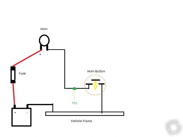
In the horn circuit above, the R/S system would supply a (-) output signal to TP1 to allow
the R/S system to beep the horn. This wire at TP1 would be listed as a (-) signal in the
vehicles wiring guide. When using a DMM to locate / verify this wire, it would be set to
20V DC. The Red lead would be connected to +12V ( battery positive terminal ) and the Black
lead would be connected to TP1. When the horn button is depressed the DMM would read +12V
because its' Red lead is connected to the batteries positive terminal and the Black lead is
now connected to chassis ground ( aka the batteries negative terminal ) thru the horn button.
------------- Soldering is fun!
Posted By: howie ll
Date Posted: September 21, 2012 at 1:26 AM
And here is the number one reason why I use a test light!
Throw over the catch at the rear of the driver door, close all other doors, ground the clip end of the Snap-On CT-42 or MAC equivalent*, probe the other end to each suspected wire and you will activate the lock and unlock if you have the correct wires. It's that simple.
You'll drive yourself mad with those meter readings.
* Or even a marker light with it's attached wires from a wreck.
One side to ground other to suspect wires.
-------------
Amateurs assume, don't test and have problems; pros test first. I am not a free install service.
Read the installation manual, do a search here or online for your vehicle wiring before posting.
Posted By: howie ll
Date Posted: September 21, 2012 at 1:29 AM
And yes I know I'm going to get adverse comments BUT were talking about simple voltage (as explained by Kregg) devices here.
A test light is faster, easier to use and actuates the locks.
-------------
Amateurs assume, don't test and have problems; pros test first. I am not a free install service.
Read the installation manual, do a search here or online for your vehicle wiring before posting.
Posted By: alexp1289
Date Posted: September 21, 2012 at 9:19 PM
I couldn't agree more Howie. I went out and purchased a bulb tester for $7 I got home and clipped the clip to chassis ground and started probing wires (poked them actually). After 5 minutes of being on my back inside the kick panel while poking multiple light blue and white wires I found them both :-P Best $7 I ever spent for a tester. Like Howie said the car locked and unlocked when I poked the correct wires :-D
Posted By: howie ll
Date Posted: September 22, 2012 at 1:29 PM
I have to post a disclaimer here.
Use a test light with discretion.
It only works on "solid" 0v lo and 12v hi wiring.
Any use on suspected DATA or airbag wiring and you're up s**t creek without a paddle.
-------------
Amateurs assume, don't test and have problems; pros test first. I am not a free install service.
Read the installation manual, do a search here or online for your vehicle wiring before posting.
Posted By: alexp1289
Date Posted: September 26, 2012 at 4:28 PM
Anyone know of an H1 and H2 (6-pin connector and 24-pin connector) list of wires and connections? I didn't see any in vehicle wiring database. I'm having a hard time guessing what wires attach to what. Some are simple and self explanatory others I'm at a loss. I've got my lock wires set up and working perfectly so I'm good with that :-)
Posted By: alexp1289
Date Posted: September 26, 2012 at 4:32 PM
Actually there's a list but its not very specific it shows the car wires and colors but not viper connections.
Posted By: alexp1289
Date Posted: September 26, 2012 at 6:18 PM
Please? Anyone :-(
Posted By: offroadzj
Date Posted: September 26, 2012 at 6:27 PM
Do you at least have the colors? I haven't looked back in the thread, but is this a DEI?
-------------
Kenny
Owner / Technician
KKD Garage LLC
Albany, NY 12205
Posted By: alexp1289
Date Posted: September 26, 2012 at 6:56 PM
Yes this is a viper 5704 remote start and alarm. The wires that I'm having trouble with are:
H1/4-(white, brown) parking light isolation wire
H1/5-(white)parking light output
H1/6-(orange) (-) 500mA ground when armed output
H2/1-(pink, white) (-) 200mA ignition / flex relay control output
H2/10-(pink) (-) 200mA ignition 1 output
H2/18-(violet,yellow) (-) 200mA starter output
H2/22-(orange) (-) 200mA accessory output "think it needs a diode"
Posted By: offroadzj
Date Posted: September 26, 2012 at 7:29 PM
Ok. Here is what I know:
WHITE/ brown - parking light isolation --> This wire is not required for the remote start. It is used only on vehicles where the parking light wire has to be cut to prevent back feeding into the switch.
White - Parking light output --> This wire connects to your vehicle parking light wire (+). On that car it is brown at the switch.
Orange - Ground when armed output --> This wire shows a ground whenever the alarm is armed. It is normally not used.
Pink/White - This wire is a programmable output that connects to a 2nd ignition, 2nd accessory, or 2nd starter. On that car, you would want to use it as 2nd ignition (white at the ignition switch) and then use your (-) 200ma 2nd accessory output to drive a relay for the brown 2nd accessory wire at the ignition.
Pink - This is your main ignition output for the remote start. Connect it to the pink wire at the ignition switch.
Violet / YELLOW - ONly required on vehicle with a 2nd starter wire. Not used on your car.
Orange - See (-) 200mA accessory output above.
As with any connections, ALWAYS test the wiring before making any connections.
-------------
Kenny
Owner / Technician
KKD Garage LLC
Albany, NY 12205
Posted By: kreg357
Date Posted: September 26, 2012 at 8:16 PM
24-pin connector
H2/1 PINK/WHITE (-) 200mA IGNITION/FLEX RELAY CONTROL OUTPUT
H2/2 BLACK/ WHITE (-) NEUTRAL SAFETY INPUT
H2/3 BLUE/WHITE (-) 200mA 2ND STATUS /REAR DEF0GGER OUTPUT
H2/4 GREEN/ BLACK (-) 200mA OEM ALARM DISARM 0UTPUT
H2/5 RED / WHITE (-) 200mA TRUNK RELEASE 0UTPUT
H2/6 GREEN (-) D00R TRTGGER INPUT (N/C 0R N/0)
H2/7 BLACK / YELLOW (-) 200mA D0ME LIGHT SUPERVISI0N 0UTPUT
H2/8 BROWN / BLACK (-) 200mA HORN H0NK 0UTPUT
H2/9 DARK BLUE (-) 200mA STATUS OUTPUT
H2/10 PINK (-) 200mA IGNITI0N 1 OUTPUT
H2/11 WHITE/ BLACK (-) 200mA AUX 3 0UTPUT
H2/12 VIOLET (+) D00R TRIGGER INPUT
H2/13 WHITE/ VlOLET (-) 200mA AUX 1 OUTPUT
H2/14 VIOLET/BLACK (-) 200mA AUX 2 0UTPUT
H2/15 ORANGE / BLACK (-) 200mA AUX 4 0UTPUT
H2/16 BROWN (+) BRAKE SHUTD0WN INPUT
H2/17 GREY (-) H00D PIN INPUT (N/C 0R N/0)
H2/18 VIOLET / YELLOW (-) 200mA STARTER 0UTPUT
H2/19 BLUE (-) TRUNK PIN/ INSTANT TRIGGER INPUT (N/C OR N/O)
H2/20 GREY/BLACK (-) DIESEL WAIT T0 START INPUT
H2/21 WHITE/ BLUE (-) REMOTE START/ TURBO TIMER ACTIVATION INPUT
H2/22 ORANGE (-) 200mA ACCESSORY 0UTPUT
H2/23 VIOLET/WHITE TACHOMETER INPUT
H2/24 GREEN / WHITE (-) 200mA OEM ALARM ARM OUTPUT
Viper consolidated several connectors. The wire color and associated description/purpose should be the same. ------------- Soldering is fun!
Posted By: alexp1289
Date Posted: September 26, 2012 at 8:38 PM
Thanks kreg, I have the sheet with that info. I just didn't know where they connected or if some were needed.
Posted By: offroadzj
Date Posted: September 26, 2012 at 9:40 PM
Refer to my last post.. that should give you the rundown of the ones you listed.
-------------
Kenny
Owner / Technician
KKD Garage LLC
Albany, NY 12205
Posted By: alexp1289
Date Posted: September 27, 2012 at 3:30 PM
Door triggers should be at the bcm? Just like the lock and unlock wires? I'm having a lot of trouble locating the dark blue trigger in the passenger kick. If anyone has pictures of there locations I'd be greatful :-) Can I catch the passenger trigger @ bcm? Also is there a way to test for these wires?
Posted By: alexp1289
Date Posted: September 27, 2012 at 4:02 PM
Found factory disarm :-D still need some help on door triggers.
Posted By: tommy...
Date Posted: September 27, 2012 at 4:05 PM
Only pic is for drivers side Tan- Door Trigger...
This is a pic of the Dis-arm...
https://directechs.com/DirectWire/PrintPhotoNotesBox.aspx?VehicleID=5203&Item=fctalm1
Lock: Unlock is right next to it in the Pic...
https://directechs.com/DirectWire/PrintPhotoNotesBox.aspx?VehicleID=5203&Item=pu
-------------
M.E.C.P & First-Class
Go slow and drink lots of water...Procrastinators' Unite...Tomorrow!
Posted By: alexp1289
Date Posted: September 27, 2012 at 4:09 PM
It wants me to log in to view the picture. Could you post it here or email it to me?
alexp1289@gmail.com
Posted By: alexp1289
Date Posted: September 27, 2012 at 4:12 PM
If anyone is wondering. I've got all the other wires connected. Just need help on door triggers. This is driving me nuts. Its like where's Waldo only a f'ing wire 0_0
Posted By: alexp1289
Date Posted: September 27, 2012 at 5:24 PM
Does poking the correct wire with a test light (door trigger) set off the alarm? Or is there a better way to test for the wire?
Posted By: offroadzj
Date Posted: September 27, 2012 at 5:59 PM
You can use a meter to test the door trigger. The wire should show ground when the door is open. Here is what I show for the door triggers: The tan is located in the drivers kick and catches only the drivers door. The dark/blue is located in the passenger kick panel and catches all other doors, must diode isolate these wires. Is there a visible door pin on the B-pillar?
-------------
Kenny
Owner / Technician
KKD Garage LLC
Albany, NY 12205
Posted By: alexp1289
Date Posted: September 27, 2012 at 8:52 PM
I found a grey and black wire in driver side kick. When I poke it with test light the dome lights come on (this is with all doors closed). When I open any door the bulb on the test light goes out. The tan wires don't do anything when probed with my test light. On passenger side I found a dark blue that when probed turns on dome light. Did I find the correct wires? Even though its different color in driver kick? I'm so lost.
Posted By: alexp1289
Date Posted: September 27, 2012 at 9:23 PM
Stupid tan door trigger was at bcm with disarm and lock wires!! Grrrrrr :-P finally found it. Now to go to bed and work on it tomorrow lol.
Posted By: alexp1289
Date Posted: October 05, 2012 at 1:37 AM
Ok so I'm looking for the passkey 3 harness on my ignition. There's a ton of small gauge wires. One set of wires has all the colors I need and there's green tape wrapped around those wires (and there's a connector). I tried tapping into those wires like the diagram said (even looked at the passkey 3 module and it looks like those are the same group of wires I soldered to). Got everything hooked up and car started but I was a little skeptical so I unhooked the connector which was after my soldering joints and the damn car still started!! I figured if passkey 3 wasn't plugged in it wouldn't start? So idk if I got the right wires or not. And not sure how I'd test for the ones I need if I have to redo the connections. Someone please give me some guidance :-)
Posted By: alexp1289
Date Posted: October 05, 2012 at 1:52 AM
If no one knows if I have the right wires that's ok. But I would need help on testing for the right wires.
Posted By: alexp1289
Date Posted: October 05, 2012 at 2:06 PM
H2/18- violet / YELLOW starter output goes to starter output on 10 pin harness?
Posted By: kreg357
Date Posted: October 05, 2012 at 2:29 PM
Absolutely not.
H2/18 (-) 200mA Starter Output is a low current negative output typically used to control a relay if the vehicle needs more than one high current (+) output.
H3/4 Violet (+) Starter Output is a high current +12V output used to connect directly to the vehicles ignition harness ( if it is required ).
H3/5 Green is used in conjunction with H3/4 if the Vipers optional Starter Kill circuit is desired. ------------- Soldering is fun!
Posted By: kreg357
Date Posted: October 05, 2012 at 2:51 PM
G.P. wiring info from Ready Remote
Viper 2002 G.P. @ Ignition Switch Harness
H3/1 PINK (+) IGNITION 1 INPUT/OUTPUT Pink
H3/2 RED / WHITE (30A) FUSED IGNITION 2 Red
H3/3 ORANGE ACCESSORY OUTPUT Orange
H3/4 VIOLET (+) STARTER OUTPUT (CAR SIDE) Yellow - cut
H3/5 GREEN (+) STARTER INPUT (KEY SIDE) Yellow - cut
H3/6 RED (+) FUSED (30A) IGNITION 1 INPUT Red
H3/7 PINK/WHITE (+) IGNITION 2 White ***Viper set for IGN2 ( default )
H3/8 PINK/BLACK FLEX RELAY INPUT 87A N.U.
H3/9 RED / BLACK FUSED (30A) ACC/STARTER INPUT Red
H3/10 N/C N/C
If you want to power the G.P.'s Brown Accessory2 circuit, wire a 30/40 Amp SPDT relay as follows :
Relay Pin 86 and 87 to +12V constant fused at 20 Amps
Relay Pin 30 to G.P. Brown ACC2 wire @ ignition switch harness
Relay Pin 85 to Viper ORANGE (-) 200mA ACCESSORY OUTPUT wire
Relay Pin 87A not used - insulate
All vehicle wires should be verified before any connections are made. All the above vehicle wires
are simple +12V circuits. You can use a DMM or low current test light to locate, identify and verify
each wire. Black lead to chassis ground and Red lead to suspect wire. DMM will indicate +12V when
circuit is active.
Here is a link to some videos for installation basics : https://www.readyremote.com/default.asp
Here is a link to an install guide with wire identification info :
https://www.the12volt.com/installbay/file.asp?ID=1010 Starting at Step 2 on page 14 ------------- Soldering is fun!
Posted By: alexp1289
Date Posted: October 05, 2012 at 3:04 PM
I'm trying to do the 24-pin H2 connector but as you've said H2 wires are low current. So they don't connect to the h3 harness in any way but I'm trying to figure out where the H2 wires go on the steering column. There's some small wires but I can't tell what any of them are cause there's no sheet telling me which is which.
Posted By: kreg357
Date Posted: October 05, 2012 at 3:05 PM
Just noticed that all the above H3 wiring info was previously posted on Page 3...  ------------- Soldering is fun!
Posted By: alexp1289
Date Posted: October 05, 2012 at 3:05 PM
I've got all the H2 wires hooked up except for the remote start H2 wires.
Posted By: kreg357
Date Posted: October 05, 2012 at 3:16 PM
There are several different H2 harness configurations. It might help if you actually listed your H2 harness wires and each connection you have made with any questions concerning the "unused" wires. ( There will be "unused" wires. )
-------------
Soldering is fun!
Posted By: alexp1289
Date Posted: October 05, 2012 at 8:24 PM
Alright so these are the connections I've already made with the harness. So far I've already done:
These wires have already been attached and tested :-)
H2/4 "GREEN/ black"-(-)200mA oem alarm disarm output
H2/6 "green"-(-) door trigger input
H2/7 "BLACK / YELLOW"-(-)200mA dome light supervision output
H2/8 "BROWN / black"-(-)200mA horn honk output
H2/16 "brown"-(+) brake shutdown input
The wires I need help with are (none of these go to heavy gauge ignition wires? Correct?)-
H2/1 "pink/white"-(-)200mA ignition/ flex relay control output
H2/10 "pink"-(-)200mA ignition 1 output
H2/18 " violet / YELLOW "-(-)200mA starter output
H2/21 ""-(-)200mA remote start/ turbo timer activation
H2/22 "orange "-(-)200mA accessory output ......does this need a diode? And which way would the diode go?
H3/4 "violet"-(+) starter output (car side of starter kill).... I read somewhere that this wire is not required for the remote start but it seems like in order to remote start the car you would need a starter output and input so I'm guessing that information was wrong.
H3/5 "green"-(+) starter input (key side of starter kill).... I also read that this wire was not needed but I don't see how you would start a car without a starter input.
Posted By: kreg357
Date Posted: October 05, 2012 at 8:51 PM
Don't need for your install:
H2/1 "pink/white"-(-)200mA ignition/ flex relay control output
H2/10 "pink"-(-)200mA ignition 1 output
H2/18 " violet / YELLOW "-(-)200mA starter output
H2/21 ""-(-)200mA remote start/ turbo timer activation
Needed for install if using external relay to power the G.P.'s Brown ACC2 wire. Diagram already listed.
Diode not needed but could be added as a quenching diode across the relays coil ( Pins 85 & 86 ) as
Howie II has probably mentioned.
H2/22 "orange "-(-)200mA accessory output
Your G.P. will need the Vipers Starter output connected to remote start the car. If you don't want the
Starter Kill feature, only connect the H3/4 Violet wire to the G.P.'s un-cut Yellow Starter wire.
H3/4 "violet"-(+) starter output (car side of starter kill) - must be used
If you want the Vipers Starter Kill feature, cut the G.P.'s Yellow starter wire and connect both the
Vipers Violet and Green wires to the correct ends of the G.P.'s cut Yellow Starter wire
H3/5 "green"-(+) starter input (key side of starter kill) - optional - wire accordingly ------------- Soldering is fun!
Posted By: alexp1289
Date Posted: October 05, 2012 at 9:01 PM
Ok cool. I understand that a lot more clearly lol. I will follow that and hopefully will have no more issues. Kept getting "remote start error " so I was getting pretty agitated lol.
Posted By: alexp1289
Date Posted: June 04, 2013 at 9:05 PM
Hey guys so my car ended up sitting for a long while and needed more repairs so the alarm took a back seat since money was tight. So anyways finally got some nice weather to work in the driveway and now I'm finishing the project finally. Few questions for you guys. On my xk05 bypass there's a wire called ground when running input and its supposed to connect to the viper ground when running output I would think but I looked at the list of wires I have coming from the viper 5704 alarm and don't see a wire that fits that description either that or I'm lost. If you haven't forgotten I really don't know too much about this stuff so I'm trying to teach myself so bear with me even though this has been quite a long forum thread I understand. I've definitely been learning a lot but there's still some gray areas. Also there's a neutral safety switch wire coming off of the alarm and I look some of that up and it looks like I can just put it to a chassis ground because my car is an automatic correct?
Posted By: kreg357
Date Posted: June 04, 2013 at 9:25 PM
XK05 Ground When Running to Viper Dark Blue (-) 200 mA Status Output.
Neutral Safety Switch wire to chassis ground if Auto Trans. Verify that G.P. won't crank when gear shift is NOT in Park or Neutral.
-------------
Soldering is fun!
Posted By: alexp1289
Date Posted: June 04, 2013 at 9:28 PM
Oh cool thats what I thought so I'm getting better at this stuff :D
Posted By: alexp1289
Date Posted: June 05, 2013 at 4:45 PM
OK I tried multiple times and me keep getting 8 flashes from the system. Also the viper isn't in manual transmission mode. I had 7 flashes at first now 8 :(
Posted By: alexp1289
Date Posted: June 05, 2013 at 5:07 PM
I have it hooked up to the same wire for the system chassis ground. So I know that ground works.
Posted By: alexp1289
Date Posted: June 05, 2013 at 6:31 PM
Even though my car is an automatic do I still need the neutral safety switch plugged in and on? Cause I'm looking over everything and I never bothered to plug mine in because my car is an automatic there for I didn't think I needed it. The manual said it must be plugged in and in the on position so could that be why I'm still getting 8 flashes?
Posted By: kreg357
Date Posted: June 05, 2013 at 7:01 PM
Yes, the Neutral Safety Switch must be plugged in and set to ON, even for Auto Trans vehicles.
-------------
Soldering is fun!
Posted By: alexp1289
Date Posted: June 05, 2013 at 7:05 PM
Okay I'm not getting any more error codes with the remote start when I tell it to remote start it tries to turn on but it doesn't turn over the vehicle I think it's because I have to program it now that I've got everything hooked up correctly so lets all have a laugh about this cause I'm pretty ditzy I guess lmao. This is a fitting video so have a laugh kreg :P
https://www.youtube.com/watch?v=I03UmJbK0lA&feature=youtube_gdata_player
Posted By: alexp1289
Date Posted: June 05, 2013 at 7:10 PM
Do I qualify for the super noob of the year lol? I definitely deserve it haha. And once again you guys are the best and so helpful so many thanks :) I'll update the thread if I need more assistance.
Posted By: kreg357
Date Posted: June 05, 2013 at 7:35 PM
It lives!!!!!  ------------- Soldering is fun!
Posted By: howie ll
Date Posted: June 05, 2013 at 7:46 PM
Still not our record yet, Kregg. ------------- Amateurs assume, don't test and have problems; pros test first. I am not a free install service.
Read the installation manual, do a search here or online for your vehicle wiring before posting.
Posted By: alexp1289
Date Posted: June 05, 2013 at 7:52 PM
Okay I'm trying to think of some reasons why the car will only go into the on position with the Viper and I'm trying to figure out why it won't try to turn over could it be because I haven't programmed it yet or is it because I have something with the ignition wires hooked up wrong? I can hear the fuel pump and the headlights turn on and so that must mean I'm pretty close. Obviously I'm going to check the ignition wires but what else should I check that you guys can think of?
Posted By: alexp1289
Date Posted: June 05, 2013 at 10:11 PM
Okay I look at the ignition harness a little bit and I have a question for you guys. I was looking at my remote start wiring instructions you gave me for wiring the heavy gauge wires it says that H3/2 and h3/6 need to go to the red wire on the Grand Prix but I have H3/2 going to red which is a 12 volt constant source h3/6 is going to the RED / white wire on my Grand Prix. Is that going to cause my issue or is that okay because they're both 12 volt constant wires. H3/2 & h3/6 are both 12 volt constant inputs right?
Posted By: howie ll
Date Posted: June 06, 2013 at 4:19 AM
TEST
-------------
Amateurs assume, don't test and have problems; pros test first. I am not a free install service.
Read the installation manual, do a search here or online for your vehicle wiring before posting.
Posted By: alexp1289
Date Posted: June 06, 2013 at 4:26 AM
I know they're both 12 volt constant inputs but I just wanted to have one of you guys confirm what I'm thinking just to double check.
Posted By: kreg357
Date Posted: June 06, 2013 at 6:34 AM
H1/1, H3/2, H3/6 and H3/9 should all go to +12V constant ( plus the XK05 Red if going W2W ). While I can't remember exactly
on a 2002 G.P., it is common for GM to use two Red's or one Red and one RED / White at the ignition harness during that time
frame. As Howard says, test. I actually test at least twice during the install ( first time to locate / verify and a second time
just prior to soldering ) to ensure all wires are connected to the correct vehicle wires.
-------------
Soldering is fun!
Posted By: howie ll
Date Posted: June 06, 2013 at 6:44 AM
Just wondering how our friend would cope with a Noble GT car I did yesterday.
Built in South Africa using a a South African made Conlog* Cat 1 alarm.
It took me longer to test and verify the original alarm wires, all Cat l alarms use black for power and grounds and cuts.
Unlike some where you trace those blacks to the cuts, the whole loom was prepared that way.
Think about removing and temporarily restoring ignition and start before installing the 5704!
Hence the importance of test and verification.
The hardest part for me was getting in and out of the driver's Corbeau chair to test MTS reservation and turbo timer (Ford 3.0 Durotorque with 2 X turbos).
*Viper equivalent for Africa.
-------------
Amateurs assume, don't test and have problems; pros test first. I am not a free install service.
Read the installation manual, do a search here or online for your vehicle wiring before posting.
Posted By: kreg357
Date Posted: June 06, 2013 at 6:54 AM
Sounds like a cramped work area. Glad it was your spine, not mine.
-------------
Soldering is fun!
Posted By: howie ll
Date Posted: June 06, 2013 at 8:46 AM
Most in the toeboard, the cramped area was getting in and out of the driver's chair.
Other sillies like both sides of the brake switch being RED / black.
Also using their own South African sourced loom, nothing like the Ford wiring (change every 3 years, one wire colour for multiple functions etc) we've got to know and love.
-------------
Amateurs assume, don't test and have problems; pros test first. I am not a free install service.
Read the installation manual, do a search here or online for your vehicle wiring before posting.
Posted By: alexp1289
Date Posted: June 06, 2013 at 5:06 PM
I got everything up and running the remote start works perfectly car runs and drives perfect the only problem I'm having now is the security light keeps flashing when I remote start it. Is there any way to fix this if not I can live with it lol.
Posted By: howie ll
Date Posted: June 06, 2013 at 5:12 PM
Relay open circuit it from a GWR wire.
-------------
Amateurs assume, don't test and have problems; pros test first. I am not a free install service.
Read the installation manual, do a search here or online for your vehicle wiring before posting.
Posted By: alexp1289
Date Posted: June 06, 2013 at 5:15 PM
Would you be able to explain and give me some directions for that or direct me to where there are directions I am familiar with relays but I just need a little bit more help on what you're explaining.
Posted By: howie ll
Date Posted: June 06, 2013 at 5:24 PM
Here you go. blocking_warning_lamp.bmp------------- Amateurs assume, don't test and have problems; pros test first. I am not a free install service.
Read the installation manual, do a search here or online for your vehicle wiring before posting.
Posted By: alexp1289
Date Posted: June 06, 2013 at 5:36 PM
Which wire on the alarm do I have to connect it to so that the relay activates? Still a little confused can you be a little bit more exact to my alarm setup. With the wire that I have to cut be the wire going directly to the security light socket with the bulb in it and which one would I have to use the positive or the negative wire of the socket? Trying to figure out exactly what I need to do. The diagram you gave me is very helpful I just need a little bit more help on exactly what wires I'm using.
Posted By: howie ll
Date Posted: June 06, 2013 at 9:09 PM
H2/9 or H2/21 goes to 85.
It doesn't matter which of the the two wires to the bulb you cut.
If you require any more help don't attempt it, you can't understand it. I'm going to suggest you read the sections on relays and diodes this is too basic for me to start teaching you. Do some research.
All the diagram does is to use the relay as an on-off switch to break the bulb's circuit.
-------------
Amateurs assume, don't test and have problems; pros test first. I am not a free install service.
Read the installation manual, do a search here or online for your vehicle wiring before posting.
Posted By: alexp1289
Date Posted: June 07, 2013 at 11:11 AM
Howie, there's absolutely no reason to be condescending I was just asking for simple explanation that's all :)
Posted By: howie ll
Date Posted: June 07, 2013 at 12:19 PM
But it wouldn't be simple enough.
Just follow that diagram.
-------------
Amateurs assume, don't test and have problems; pros test first. I am not a free install service.
Read the installation manual, do a search here or online for your vehicle wiring before posting.
Posted By: alexp1289
Date Posted: June 07, 2013 at 1:00 PM
I'm not someone that looks at diagrams every day so I wasn't comfortable touching it till I understood what I was looking at :)
Posted By: howie ll
Date Posted: June 07, 2013 at 1:05 PM
OK but the second post explained the wires, use H2/21 if you're already using H2/9 for a by-pass.
Logically it doesn't matter which bulb wire you cut, you're still breaking the circuit.
That's why I took umbrage, you didn't appear to think it through.
-------------
Amateurs assume, don't test and have problems; pros test first. I am not a free install service.
Read the installation manual, do a search here or online for your vehicle wiring before posting.
Posted By: alexp1289
Date Posted: June 08, 2013 at 10:27 AM
OK one last thing to figure out. I hooked up my rear defrost to the H2/3= blue/white. Now since h2/3 is also second status output as well as rear defogger output. Problem is that the viper turns on the relay that activates my rear defrost EVERY time I remote start my car. I know the relay is hooked up correctly. Do I have to program h2/3 specifically for rear defogger so the viper only does it below 55 degrees farenheit. The relay keeps getting activated by remote start because of the second status output.
Posted By: alexp1289
Date Posted: June 08, 2013 at 10:31 AM
I know its the viper alarm that's activating the rear defrost on remote start because when I start it manually the rear defrost doesn't automatically turn on, so everything is working as it should its just coming on every single time I start the car with the remote start. And it's fairly warm around here so it's nowhere near close enough for the window to be fogged up.
Posted By: kreg357
Date Posted: June 08, 2013 at 10:38 AM
Yes, programming is required. You can use it for either Status Output or Defroster,
not both. See Menu 3 , Item 11, Option 2 ( for latched operation ).
Here is the write up :
3-11 2nd STATUS OUTPUT: NORMAL: This feature will allow selection of status
output or a rear defogger mode that turns on ten seconds after the vehicle has
started if the vehicle interior temperature is below 55 degrees F. The defogger
mode has two selections, latched, the LED will flash twice, or pulsed, the LED will
flash three times. Latched mode will only stay on for 10 minutes.
Note: When the defogger mode is on, the output will always be active and can
be turned on independently with the remote for a one-time activation. (See the
Remote Functions table.) ( Function Button 4 times, then the Remote Start button. )
-------------
Soldering is fun!
Posted By: howie ll
Date Posted: June 08, 2013 at 10:38 AM
You could use an aux output instead, set as timed, linked to remote start, latched with ignition.
Simpler to try this:- start your engine, turn on HRW (rear defroster to you colonials), turn off engine.
Now restart, does the HRW stay on? If so, job done, just leave it on the night before.
Does it come on automatically below say 55f?
Mine does below 51f so no problem.
Last make one of your aux outputs link to R/Start and then as I said latched, you'd have to press the relevant control on your remote to activate it.
There that covers it.
-------------
Amateurs assume, don't test and have problems; pros test first. I am not a free install service.
Read the installation manual, do a search here or online for your vehicle wiring before posting.
Posted By: howie ll
Date Posted: June 08, 2013 at 10:40 AM
Oh here we go again Kregg, you posted as I was finishing off!
Talk about great minds etc.
-------------
Amateurs assume, don't test and have problems; pros test first. I am not a free install service.
Read the installation manual, do a search here or online for your vehicle wiring before posting.
Posted By: alexp1289
Date Posted: June 08, 2013 at 11:28 AM
I really want to keep it on h2/3 since that's its purpose. If I get a bitwriter off eBay I can change the settings with that easily right? I'm looking at the dei 998t.
Posted By: howie ll
Date Posted: June 08, 2013 at 11:33 AM
Why would you need a Bitwriter you aren't installing 2-3 a week are you?
Menu 3, Item 11 option 2 or 3.
-------------
Amateurs assume, don't test and have problems; pros test first. I am not a free install service.
Read the installation manual, do a search here or online for your vehicle wiring before posting.
Posted By: alexp1289
Date Posted: June 08, 2013 at 11:36 AM
What button sequence do I have to use to get there using the control center button?
Posted By: howie ll
Date Posted: June 08, 2013 at 11:50 AM
Open driver's door.
Turn ignition on and off.
Press and hold control centre button until you get 3 chirps.
Press the control button 11 times, release then hold.
Siren will chirp 11 times.
Release button then press any button on your remote, that gives you option 1 latched.
Turn ignition on-off to exit, siren sounds like someone just trod on your cat, all done.
This is all in the quick reference install guide that would have been in your unit's packaging.
-------------
Amateurs assume, don't test and have problems; pros test first. I am not a free install service.
Read the installation manual, do a search here or online for your vehicle wiring before posting.
Posted By: howie ll
Date Posted: June 08, 2013 at 11:51 AM
It's actually faster that way than through the Bitwriter.
-------------
Amateurs assume, don't test and have problems; pros test first. I am not a free install service.
Read the installation manual, do a search here or online for your vehicle wiring before posting.
Posted By: alexp1289
Date Posted: June 08, 2013 at 11:56 AM
Cool I just did that right now and it's fixed it no longer comes on automatically when its warm :)
|
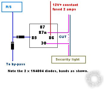