viper 4103 remote start, ’89 535i
Printed From: the12volt.com
Forum Name: Car Security and Convenience
Forum Discription: Car Alarms, Keyless Entries, Remote Starters, Immobilizer Bypasses, Sensors, Door Locks, Window Modules, Heated Mirrors, Heated Seats, etc.
URL: https://www.the12volt.com/installbay/forum_posts.asp?tid=131960
Printed Date: May 01, 2026 at 8:09 PM
Topic: viper 4103 remote start, ’89 535i
Posted By: hipmusicman
Subject: viper 4103 remote start, ’89 535i
Date Posted: August 05, 2012 at 7:32 PM
i hooked up the remote start harness, the ground, the tach, the antenna, and the door locks. the door locks work (had to get a relay for it but it wasn't a big deal to wire it). the problem im having is that the when i press the button for the remote start it wont turn the car over. it wont even start the accy. there is another harness called the satellite harness but it's just for when you put the key in the ingnition i think. and if it's not how do i hook it up because that is the only other harness besides the kill switch that i havented installed.
im installing this in an '89 535i. what am i missing or doing wrong?
Replies:
Posted By: chev104275
Date Posted: August 05, 2012 at 8:12 PM
What did you do with the gray hood pin wire ? It Shouldn't be grounded and the neutral safety wire BLACK/ white should be grounded if its an automatic
-------------
If i Can't Install it I Don't need it Joe
Posted By: kreg357
Date Posted: August 05, 2012 at 8:22 PM
Hard to say at this point. The 4103 is for use on a F.I., auto trans vehicle so
we will assume your BWM has an auto trans. ( If it does not, then DO NOT install
this remote start system on your car. There are other units available designed
to be safe with a manual transmission. )
Here is wiring info. Verify all wires with a DMM prior to connection.
H1/1 LIGHT GREEN/ BLACK FACTORY ALARM DISARM
H1/2 GREEN / WHITE FACTORY REARM
H1/3 YELLOW (+) IGNITION OUT (TO ALARM)
H1/4 WHITE/ BLUE (-) ACTIVATION INPUT
H1/5 ORANGE (-) GROUND WHEN LOCKED
H1/6 BROWN (-) HORN OUTPUT
H1/7 RED / WHITE (-) TRUNK RELEASE OUTPUT
H1/8 BLACK GROUND Chassis Ground
H1/9 WHITE (+/-) LIGHT FLASH gry/purple, gry/yel @ light switch
Set 4103 to (+) and use diodes or relay to isolate wires.
Here is a diagram from Bulldog Security :
https://www.bulldogsecurity.com/diagrams/extrainfo/diagrams/14301_5-SERIES_DUAL%20PARKING%20LIGHT%20DIAGRAM.pdf
H2/1 BLACK/ WHITE (-) NEUTRAL SAFETY SWITCH INPUT to Chassis Ground
H2/2 VIOLET/WHITE TACHOMETER INPUT WIRE black (AC) @ diagnostic conn.
H2/3 BROWN (+) BRAKE SWITCH SHUTDOWN WIRE blue/red (+) brake pedal switch
H2/4 GRAY (-) HOOD PINSWITCH SHUTDOWN WIRE Hood Pin
H2/5 BLUE/WHITE (-) 200mA 2ND STATUS/REAR DEFOG N.U.
1 PINK (+) (30 AMP) OUTPUT TO IGNITION CIRCUIT Green @ Steering Column
2 PURPLE (+) (30 AMP) OUTPUT TO STARTER CIRCUIT BLACK / YELLOW @ Steering Column
3 ORANGE (+) (30 AMP) OUTPUT TO ACCESSORY CIRCUIT Purple @ Steering Column
4 RED (+) (30A) HIGH CURRENT 12 INPUT Red @ Steering Column
5 PINK/WHITE (+) PROGRAM OUTFOR ACC2 OR IGN2 N.U.
6 RED (+) (30A) HIGH CURRENT 12V INPUT Red @ Steering Column
Neutral Safety Switch must be plugged in and set to ON.
Program 4103 to Tach Mode and perform Tach Learn process.
Use the built in diagnostics to determine fault :
led flashes shutdown mode
1 System timed out
2 Over-rev shutdown
3 Low or no RPM, Low battery (for voltage & virtual tach modes)
4 Transmitter Shutdown (or optional push button)
5 (-) hood shutdown
6 (+) brake shutdown
7 Neutral safety ------------- Soldering is fun!
Posted By: hipmusicman
Date Posted: August 05, 2012 at 8:23 PM
the hood pin wire isn't grounded i might not even install it. i didn't ground the neutral wire though. should i?
Posted By: hipmusicman
Date Posted: August 05, 2012 at 8:29 PM
im guessing that the safety switch goes between the neutral wire and the chassis?
Posted By: chev104275
Date Posted: August 05, 2012 at 8:45 PM
Yes use the switch that came with the 4103 one side goes to ground and one side goes to the neutral safety wire doesn't matter which wire off the switch goes where. Why aren't you going to put the hood pin in ? It could save your mechanics hands or yours
-------------
If i Can't Install it I Don't need it Joe
Posted By: kreg357
Date Posted: August 05, 2012 at 8:49 PM
The Neutral Safety wire, BLACK/ White, must be connected and show chassis ground to allow a remote start.
Times 2 with Joe on the Hood Pin. Very important safety feature. ------------- Soldering is fun!
Posted By: auto enhancers
Date Posted: August 05, 2012 at 10:58 PM
With the range that remote start systems have now adays it is of up most importance to utilize every safety device for the remote start.
As said toggle switch to safety neutral switch. Let us know how that works out.
Posted By: hipmusicman
Date Posted: August 06, 2012 at 1:04 AM
it works perfect!!! i just need to finish the install with the brake wire and the hood pin. there is a factory hood switch so i might try to utilitize that to make it easier. the hood raises up opposite that of normal cars. most cars hoods go this way... (< = front of car) <\. mines goes this way </ and then is pushed towards the winshield to latch after it has been layed down. the whole fact that you have to push it towards the windshield makes the hood pin that came with the remote start difficult to install. therefore i will use the switch factory installed for the light or whatever it was. (there are 2 switches on the hood, one of them was for the light. neither of them work anyways). thank you for straightening this whole thing out. it's taken me a LONG time to figure it out. saved me $200 for install. all i ended up spending was about $50 for everything.
Posted By: howie ll
Date Posted: August 06, 2012 at 1:27 AM
By now after 27 years the factory hood pin needs testing to make sure it's still working, if not replace it.
Why a relay for the locks, low current neg, unless the lock module had failed.
-------------
Amateurs assume, don't test and have problems; pros test first. I am not a free install service.
Read the installation manual, do a search here or online for your vehicle wiring before posting.
Posted By: hipmusicman
Date Posted: August 06, 2012 at 11:51 AM
The locks are positive locks and require all 12 volts instead of the little things .5 that the module puts out.
I'm now having a problem with the tach. It won't show anything unless you either rev the engine up quite a bit (even then it fluxuates a lot) or you press the brake and it goes back to normal. The brake isn't hooked up to the module yet. Sounds like ur gas to do with the computer in the car. Any ideas?
Posted By: howie ll
Date Posted: August 06, 2012 at 12:33 PM
WHITE/ Green to lock and WHITE/ BLACK / YELLOW dots to unlock?
That means yours is an 89 not an 88.
Tach is black wire at the coil or black into rear of instrument panel. How are you testing for it?
-------------
Amateurs assume, don't test and have problems; pros test first. I am not a free install service.
Read the installation manual, do a search here or online for your vehicle wiring before posting.
Posted By: howie ll
Date Posted: August 06, 2012 at 12:45 PM
New hood pin to go to front scuttle I believe the original was there anyway. Use a Euro type hoodpin from DEI etc. as a direct replacement.
No tach at the diagnostic from that vintage Kregg, only from about 99.
Are you getting outputs from the R/S?
Have you tested?
By the way if you have a comfort close option you will close the windows and roof if present when you lock the car.
N.B. You won't get ACC until after the R/S has started the car.
Do me a favour, check your violet (purple) ACC wire at the ignition and tell me if it still shows 12V+ when cranking.
If so you need to connect ign 2 output wire to that wire and disconnect the R/S orange ACC from that wire.
Sorry I can't be more precise, I haven't worked on one of these since about 98!
-------------
Amateurs assume, don't test and have problems; pros test first. I am not a free install service.
Read the installation manual, do a search here or online for your vehicle wiring before posting.
Posted By: hipmusicman
Date Posted: August 06, 2012 at 2:01 PM
ok i looked into it a little more. when i dissconnect the tach wire from the remote start the problem goes away. when you test the tach wire with a dmm the voltage goes down when switched to dc as you press the gas. when switched to ac the voltage goes up. im thinking this has something to do with it. if i understand right, most cars the voltage will go up on dc when you press the gas. what do i need to fix this? do i have to hook up the wire in a different area? im not sure what's between the sensor and the tach. wiring diagrams say there's nothing.
(https://www.wedophones.com/Manuals/BMW/1989%20BMW%20525i%20-%20535i%20Electrical%20Troubleshooting%20Manual.pdf) scroll down to instrument cluster and move forward a couple pages til you find the tach.
might try finding a different wire or something.
also i haven't yet installed the brake wire into the remote start yet. do you think that could be the problem. then again it shoudln't be messing with the tach like that.
Posted By: howie ll
Date Posted: August 06, 2012 at 3:11 PM
Your last post is irrelevant and incorrect.
Irrelevant because I've already told you where the tach wire lives.
Incorrect because as I thought you don't test tach the way you described.
Set your DMM to 20VAC.
You will get a reading of 3-5VAC increasing as you rev up.
Anyway I'm making no more replies to this thread youy appear to want to blunder on regardless.
-------------
Amateurs assume, don't test and have problems; pros test first. I am not a free install service.
Read the installation manual, do a search here or online for your vehicle wiring before posting.
Posted By: hipmusicman
Date Posted: August 06, 2012 at 4:49 PM
I'm just trying to figure out what's wrong with my tach. It isn't working when connected to the remote start.
Posted By: hipmusicman
Date Posted: August 06, 2012 at 4:55 PM
I tested and tapped at back of panel.
Posted By: kreg357
Date Posted: August 06, 2012 at 6:33 PM
I believe the 4103 has a jumper setting for Tach threshold. Try switching the jumper to ON and re-learning the Tach signal. ------------- Soldering is fun!
Posted By: hipmusicman
Date Posted: August 06, 2012 at 7:11 PM
ooh! i'll try that. and how do you program the unit for start run times, door locking when key in and out of ignition and some of the others.
Posted By: kreg357
Date Posted: August 06, 2012 at 7:25 PM
Not sure if this is the latest manual, but it might help with the jumpers & programming. ( Avital is a DEI brand like Viper )
https://www.the12volt.com/installbay/file.asp?ID=738 ------------- Soldering is fun!
Posted By: hipmusicman
Date Posted: August 07, 2012 at 3:10 PM
i got everything to work. i used the "start by voltage" feature instead of the tach. it work perfect in that setting. doesn't over crank and it starts everytime. not for the little things.
thank you everyone. you've all been a big help!
Posted By: hipmusicman
Date Posted: August 10, 2012 at 10:18 AM
im trying to get the parking lights to come on when you lock and unlock the doors as well as remote start the car. i hooked up a relay to at least one of the lights but it wont even click. as much as .07 volts dc run through the parking lights wire from the remote start. do i have the wrong relay? it says 60A on the relay but i thought it was a 30A. is it just there is not enough voltage to trigger it?
also i would like to install an anti-grind relay but im not sure how to do that. the other day i turned the key too far after remote starting it from habbit when i didn't have the remote start.
Posted By: howie ll
Date Posted: August 10, 2012 at 12:16 PM
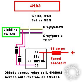
Set white wire for POS output, then through 2 x 1N5404 diodes to I think the grey / YELLOW and grey/purple at the light switch but then you didn't listen on your last post so why would you now?
-------------
Amateurs assume, don't test and have problems; pros test first. I am not a free install service.
Read the installation manual, do a search here or online for your vehicle wiring before posting.
Posted By: hipmusicman
Date Posted: August 10, 2012 at 6:25 PM
I was told to use relays but I guess in could try that
Posted By: hipmusicman
Date Posted: August 10, 2012 at 8:59 PM
i still have the question of the anti-grind
Posted By: howie ll
Date Posted: August 11, 2012 at 3:19 AM
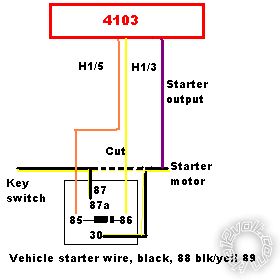
Anti grind, use this diagram, the 1N4004 between 85 and 86 is MANDATORY, otherwise fried 4103.
This will also give starter immobiliser on locking the doors, BUT I believe on a previous thread you used some kludged method of tach connection, that's why the starter grinds.
Hard wire and program tach from the black I told you about on that prior thread, where I also told you your vehicle was an 89 not as you said an 88:-
untitled_1.bmp
This is the relay method for the lights.
Again the 1N4004 diode is mandatory:- 7F8_untitled_1.bmp------------- Amateurs assume, don't test and have problems; pros test first. I am not a free install service.
Read the installation manual, do a search here or online for your vehicle wiring before posting.
Posted By: howie ll
Date Posted: August 11, 2012 at 5:06 AM
OOPS my bad you said 89 from the word go,  sorry but rest of last past still applies with regard to tach programming. ------------- Amateurs assume, don't test and have problems; pros test first. I am not a free install service.
Read the installation manual, do a search here or online for your vehicle wiring before posting.
Posted By: hipmusicman
Date Posted: August 11, 2012 at 10:50 AM
im sorry but your post is confusing me. im pretty sure i have the lights figured out so that's not my issue anymore. and as far as the tach goes i set it to voltage instead of tachometer so i don't have to hook up that wire to my tach. that problem was also solved.
as far as the anti-grind, it will only grind if i accidentally turn the key too far after remote starting. that's what i want to prevent. it's too much of a habbit to turn they key all the way when i get into the car wheather it's running or not.
Posted By: hipmusicman
Date Posted: August 11, 2012 at 10:56 AM
i think i get it now. what kind of relay do i need though? and a diode between 85 and 86?
Posted By: kreg357
Date Posted: August 11, 2012 at 2:31 PM
Standard automotive Bosch style 30/40 Amp SPDT relay, with 5 wire harness. Diode is a standard blocking diode. 1N4004 ( or 1N4007 ) will do nicely.
Here is one way to wire the relay :
Relay Pin 85 to 4103 (-) 200mA Status Output
Relay Pin 86 to BMW Ignition wire ( or 4103 Heavy Pink wire, it goes to the same place )
Relay Pin 87A to BMW cut Starter wire - Ignition Switch side
Relay Pin 30 to BMW cut Starter wire - vehicle side
Relay Pin 30 also gets the 4103 thick Violet Starter wire connected.
Relay Pin 87 not used - insulate ------------- Soldering is fun!
Posted By: howie ll
Date Posted: August 11, 2012 at 2:34 PM
If you had hooked to tach, at least three methods I can think of on that vehicle, you wouldn't have that grind problem in the first place.
In answer to your question a standard automotive 5 pin relay, from Radio Shack or any automotive distributor. Terminal 87 isn't used.
The diode is mandatory, acts as an anti spike agent when the relay shuts down, otherwise about 300volts going back and goodbye to your 4103 with no warranty.
-------------
Amateurs assume, don't test and have problems; pros test first. I am not a free install service.
Read the installation manual, do a search here or online for your vehicle wiring before posting.
Posted By: howie ll
Date Posted: August 11, 2012 at 2:46 PM
K., I've already diagrammed that except the 4103 has a yellow ignition + output wire at H1/3 for that purpose, easier than running off the (much) thicker pink.
When the poster refers to "why the diode" I worry, remember the guy who fried his unit AFTER I told him to use diodes?
-------------
Amateurs assume, don't test and have problems; pros test first. I am not a free install service.
Read the installation manual, do a search here or online for your vehicle wiring before posting.
Posted By: kreg357
Date Posted: August 11, 2012 at 3:00 PM
Oops, sorry Howard, I missed your anti-grind diagram. ( That'll teach me to text, drive and eat a corned beef sandwich at the same time while navigating a round-about..)
------------- Soldering is fun!
Posted By: hipmusicman
Date Posted: August 11, 2012 at 8:35 PM
i suppose then that means that i can't use a 4 pin relay. i understand how it all works. i'll try it out when i have time.otherwise i got the lights to work.
Posted By: hipmusicman
Date Posted: August 11, 2012 at 9:15 PM
when i try to program the 4103 to lock and unlock with ignition it wont work. i turned the key on then off. held down the program button until the light flashed once (menu 1) then pressed the button twice (feature 2 - ignition locking) held the button down and kept it down. the light flashed 2 times (indicating feature 2 is selected) then pressed the unlock button on the remote (switch feature options) but when i pressed the unlock button the light doesn't flash anymore and never indicated that option 2 has been selected (option 2 being ignition locks ON). i released the button and tried the ignition to lock the doors (even when the doors were closed) and nothing happened turned the ignition off and nothing happened. i even tried programing the unlock feature but again the light just stopped doing anything after i pressed unlock on the remote. if i pushed lock it would go back to default (which is OFF for both features) what is going on?
Posted By: hipmusicman
Date Posted: August 13, 2012 at 12:11 AM
Any ideas?
Posted By: howie ll
Date Posted: August 13, 2012 at 2:59 AM
Green door trigger wire must see ground whilst programming.
-------------
Amateurs assume, don't test and have problems; pros test first. I am not a free install service.
Read the installation manual, do a search here or online for your vehicle wiring before posting.
Posted By: hipmusicman
Date Posted: August 13, 2012 at 1:01 PM
That's odd. I have it hooked up to a relay.
Posted By: howie ll
Date Posted: August 13, 2012 at 1:05 PM
DOOR TRIGGER NOT DOOR LOCK.
-------------
Amateurs assume, don't test and have problems; pros test first. I am not a free install service.
Read the installation manual, do a search here or online for your vehicle wiring before posting.
Posted By: chev104275
Date Posted: August 13, 2012 at 1:53 PM
There's no door trigger on the 4103. Hook up the horn much easier for programming you can listen to the beeps. If your trying to get to menu 1 option 2 them hold the programming button down till you get 1 beep or led flash then release the button and press and release the button 3 times holding the button down on the 3rd press. The horn should beep twice and the led will flash twice indicating your in option 2 them from there you can toggle the options using the fob
-------------
If i Can't Install it I Don't need it Joe
Posted By: hipmusicman
Date Posted: August 13, 2012 at 9:13 PM
The thing is that it won't even select the options after you've selected the feature. The led quits doing anything. Therefore its not selecting any options for some reason and I can't figure out why.
Posted By: hipmusicman
Date Posted: August 14, 2012 at 3:04 PM
nm i got it. something weird with the programming. also the 2nd status wire doesn't do anything. i press the combined buttons, nothing. i reprogram the unit to all of the different options, and still nothing. why won't it work?
|