2012 odyssey, remote start, d2d vs w2w
Printed From: the12volt.comForum Name: Car Security and Convenience
Forum Discription: Car Alarms, Keyless Entries, Remote Starters, Immobilizer Bypasses, Sensors, Door Locks, Window Modules, Heated Mirrors, Heated Seats, etc.
URL: https://www.the12volt.com/installbay/forum_posts.asp?tid=132020
Printed Date: April 30, 2026 at 12:32 AM
Topic: 2012 odyssey, remote start, d2d vs w2w
Posted By: civiltoatee
Subject: 2012 odyssey, remote start, d2d vs w2w
Date Posted: August 17, 2012 at 8:41 AM
Hello,
I am about to start on my first install of a security-R/S system in a 2012 Honda Odyssey. I have read lots and lots of the post on this board for background info to determine if it is something I want to do. I am an avid DIYer in all areas and believe I am capable of this. That being said, I have a few general questions after reading and studying this board and other resources.
1) I am considering a number of systems with my goal being long range, LCD remote, mainly looking for R/S, but may include security. Any reason any of these systems are simpler to install or better in an Odyssey: Prestige SS6900/SS9000, Viper/Python/Clifford 5704/4704, Autopage RS915, or Compustar RF-2W900-FM/FT-6200-S.
2) I have read many posts warning about eBay purchases. Since if I install the system myself none of the above manufacturers will provide a warranty, why shouldn't I buy the hardware on eBay?
3) I have read that D2D can be less-reliable/less-stable/more-conflicts than W2W. For the small amount of investment in making the W2W connections on the bench, would you recommend this over D2D? Just to clarify, choosing W2W over D2D only affects the wiring between the brain and the bypass? The brain-to-car and bypass-to-car wiring would be indentical?
4) Should I be concerned about the brand of the bypass mod that I purchase. Surprisingly to me, I have read/heard not such good things about the Xpresskit bypasses, but are the others (idatalink/omega, fortin, Flashlogic) similar high quality units with equal compatibility with systems listed above that I am considering, especially in W2W?
Thanks in advance for any help or opinions you have on any of the above questions.
Replies:
Posted By: kreg357
Date Posted: August 18, 2012 at 9:09 PM
Welcome to the 12 Volt. As you noticed, there is a lot to know / learn with a
alarm / remote starter installation. This site has plenty of info to assist
you. Your questions are interesting and very valid.
1. Any quality brand from a major manufacturer will be good. However, they all
have their differences with strengths and weaknesses. Decide want features you need
and compare the different models to get as close as you can. Some models have
special programming that can only be accessed with a special programmer ( Bitwriter
for the Viper and OP-500 for the Compustar ). These programmers make things easy
but they cost about $70.
2. EBay can be a good supply source if you pay attention to the small print. Make
sure the unit is "new in the box" and not a re-furb. Some sellers will even give
a warranty ( from them, not the manufacturer ) and supply a minor level of tech
support.
3. While D2D simplifies the install, there are a lot of "gotcha's". There are
several types of D2D communications ( DBI, ADS and Fortin ) so the bypass module
has to match up with the R/S brain. W2W always works and allows mixing and matching
between the units ( an ADS bypass with a Viper, etc ). Making all the connections
on the bench makes it easy and keeps things neat.
4. The bypass module is another area where knowledge is the key to success. Fortin
modules come pre-loaded with firmware and work great. Xpresskit modules might require
a firmware flash prior to use ( via the XKLoader2, $40 ). The ADS iDatalink Solo
series modules come pre-flashed but the Multi series require firmware loading via
the ADS USB cable ( $45 ) and dealer registered access to their restricted WEB site.
You can find "on-line" sellers that will flash the modules for you prior to shipment
for a nominal fee.
All that being said, he's my 2 cents. Either the Viper 4704 or Compustar CM6200.
The Viper has better range, the Compustar makes remote upgrading easy. I have the
BitWriter and the OP-500 programmers, so that helps with the decision. For the
bypass module, the ADS AL CA flashed with the ADS AL(DL) HA3 is a great choice, but
for the DIYer, you would need to find a seller that can flash the module and supply
the matching install guide. The Fortin EVO-ALL is also a great choice and comes
pre-loaded. Of course, I still go W2W with the connections, can't beat a good solder
joint and heat shrink tube.
-------------
Soldering is fun!
Posted By: civiltoatee
Date Posted: August 19, 2012 at 10:00 AM
Kreg357, thank you for your thorough and thoughtful reply. I really appreciate your generosity with your knowledge.
I have a couple of follow up questions, if you don't mind.
1)The bitwriters that you talk about must be different from the cable/software/flashing that is done to a bypass. I assume it is something like changing the firmware in the brain. Are the features "accessed" by a bitwriter only available thru a bitwriter or are there other ways of accessing them? If they are only accessible thru a BW, are they features the average joe user would want to take advantage of? For those brands that don't use a BW, are those features typically not offered or accessed in some other way? What would be a couple of examples of BW accessible only features on a Viper 4704?
2) Got it. I will be careful with my sellers from eBay.
3) If I choose to go with W2W, then the varieites of D2D cable termination at the brain end becomes moot. Does W2W typically result in a more reliable system over D2D, where I have read there can be data conflicts?
4) It was disappointing to hear that Omega/Flashlogic/idatalink require a login to flash. (I just tried it and I can see that is the case). I am interested enough that I was prepared to buy the Omega flash cable and flash it myself. Otherwise, like you say, I can find a seller that says they will flash it and hope for the best or try to find a local shop that might be willing to do it for a small fee.
Finally, have you seen a good Youtube video or otherwise on making a good solder spice joint? After you strip (1/2 inch or so) of the existing wire, do you poke a hole thru the existing strands, insert the splice wire, wrap it and then solder? Or do you simply twist them in parallel and then solder? O do you even twist them at all and just lay them in parallel and then solder?
Thanks again, for all your help.
Posted By: kreg357
Date Posted: August 19, 2012 at 11:39 AM
Yes, the BitWriter and the OP-500 are different from the XKLoader2 and ADS USB cables. The BitWriter and OP-500 are only used to change the
programmable options on the Viper or Compustar units. The ADS USB cable is also used to update the firmware on the Compustar units, if you
have dealer access. Most of the normal / common options can be changed with the units remotes. However, using the remotes is a pain ( you
are relying on horn honks, parking light blinks or antenna LED flashes ) and very time consuming. There are some options that can only be
changed with the BitWriter ( or OP-500 ). If you look at the Vipers Install Guide, you will see where it is possible, using the BitWriter only, to lock
the unit so that the remotes can no longer be used to make changes. Some units sold on EBay came this way...
W2W always works. It makes things more logical. On your van, with two power sliding doors, you decide which AUX output controls each door,
etc. Some of the Flashlogic modules are re-badged ADS modules, flashed with firmware that supports the Directed DBI D2D comm protocol, but
they work the same as the corresponding ADS module in the W2W mode.
I haven't checked on YouTube for any How To's on soldering, although I'm sure there are some out there. I got my training a long time ago from
the military. There are a few threads on this site with info and even a picture. The start-up equipment costs are modest, figure about $50 for a
good soldering gun, solder, Scotch Super 33+ tape, some heat shrink tube and a nice pair of wire strippers/cutters. The strip, poke, twist and
solder method is very good but most of the time the poke is overkill with a tight twist and proper soldering. Most of my butt connections are
the old fashioned Western Union splice, solder and heat shrink tube. A little practice will give you the feel for it. The thicker gauge wires call for
more heat and a careful inspection to ensure the solder flowed properly to all areas of the wires ( no "cold" solder joint ). The auto type wire
you will be working with is braided ( not solid ) so a firm twisted mechanical connection prior to soldering works best. Sometimes the hardest
part is access / clearance under the dash... Also, soldering is a skill that can be used many places around the home.
I can PM you some online / internet vendors names that I have used in the past that were ethical and reliable if you have difficulty finding ones
you trust or feel comfortable with.
-------------
Soldering is fun!
Posted By: civiltoatee
Date Posted: August 20, 2012 at 2:51 PM
Thanks again for your response.
I looked over some of the items that are set by the BW and the corresponding codes for using the remote to access them. It does look quite complicated, but doable, especially since I won't need to do it everyday.
I have an old school Weller gun from the 60's or 70's that I already use around the house for other stuff. It's not exactly state-of-the-art, but it should suffice for the work we are talking about.
I am getting close to making my purchases, but I will let you know if I need further help before starting the install.
When reviewing the wiring diagrams on the idatalink/omega/flashlogic sites, I noticed that, along with all of the required W2W connections (or D2D), they clearly show which additional wires need to be connected from the bypass mod (BPM) to the brain (4-wires, brake, hood, trunk and door status) and from the BPM to the canbus (4-wires) and a couple of more (1-wire ground, 1-wire headlamp, maybe). What is not clear is which of the remaining wires on the brain need to be connected. Clearly some of them are connected, but since the brain install manual is printed as though you are not using a BPM, it is not clear which of those wires are made redundant by the use of the BPM.
Anyway, I hope it becomes a bit more clear when I have both pieces of hardware in my hands and I start mapping all of the wires.
Thanks again.
Posted By: kreg357
Date Posted: August 20, 2012 at 9:16 PM
If you don't need to change any special programming options, using a remote to program the brain can be done, it's just time consuming ( and frustrating ).
The Weller soldering gun will work fine. I'm still using a WEN Model 199 from the late 50's. Old Bakelite ( early plastic ) is fragile.
Some of the newer bypass module install guides show the necessary wires from the remote starter, too. Your best bet is to download all the wiring guides you can find for your mini-van and make up a master guide, noting any conflicting info. Then make up a R/S to bypass, R/S to van and Bypass to van cheat sheet. Post those for member review / input with any questions / uncertainties. Then get out the DMM for final verification and install.
-------------
Soldering is fun!
Posted By: civiltoatee
Date Posted: August 25, 2012 at 4:59 AM
Posted By: civiltoatee
Date Posted: August 27, 2012 at 4:28 PM
I have determined that I am not using a Compustar system, so an answer to the above listed question about the blade is no longer needed.
I plan to use an Autostart 6870 system with a FLCAN programmed for my '12 Odyssey. I am working on a connection diagram and may have some questions as I get it pulled together.
Thanks.
Posted By: civiltoatee
Date Posted: August 28, 2012 at 9:38 AM
I now have my hardware for use in my '12 Odyssey install: Autostart security and R/S AS-6870 with a FLCAN. Below are images of the overall wiring diagram for the Autostart brain and the '12 Ody specific FLCAN:
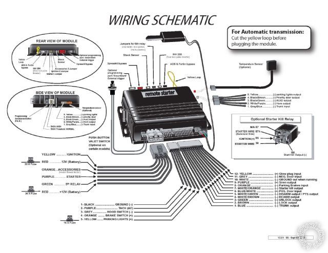
It looks like I can only have one image per post, so I will put the FLCAN in the next post.
Posted By: civiltoatee
Date Posted: August 28, 2012 at 9:44 AM
Here is the FLCAN specific to the '12 Odyssey:
-ha3-en-95092.jpg)
Posted By: civiltoatee
Date Posted: August 28, 2012 at 11:19 AM
For some reason, the FLCAN image did not appear. Here is a link to the install guide to be downloaded:
https://www.flashlogic.com/product/product/product_id/51
Here goes. This is for an '12 Odyssey with two power sliding side doors and a power lift gate. From reading the FLCAN info it does not look like it will allow for the sliders to work after a R/S without some extra relays. I am not concerned about the sliders working after R/S, but I do want them to work from the remote when the van was not R/S'd. I would also like the power liftgate to work with the remote.
I have also downloaded from DirectWire the wiring specifics for the van and the color photos of the four main connection areas: Ignition switch 5-pin plug, Canbus 7-pin plug, headlight 12-pin plug, and brake switch 4-pin plug. This should help with the connections to the van.
My main concern is making just the necessary connections from the brain to the FLCAN and to the van.
Starting at the main ignition harness:
YELLOW ........... IGNITION ---> Van, Blue Ignition wire
RED ..............12V (Battery) ---> Van, White ignition wire or should I get this directly from the battery
ORANGE ...ACCESSORIES ---> Van, orange acc. wire
PURPLE ............. STARTER ---> Van, yellow starter
GREEN ............ 5th RELAY ---> No idea where this goes or what it is for
RED ............+12V (Battery) ---> White at ignition or battery, same question as above
5 Pin Secondary Harness
BLACK () Chassis ground ---> Van, good chasis ground
PURPLE (AC) TACH input ---> FLCAN, Tach AC output PURPLE / wh
GRAY () Hood Switch input ---> FLCAN, Hood status ouput yellow
ORANGE (+) Brake Switch input ---> FLCAN, Brake output grey/red
YELLOW (+) +12 V Fused Parking Light output ---> To Van? Where? Directed printout shows wire in the passenger kick fuse box
Posted By: civiltoatee
Date Posted: August 28, 2012 at 12:33 PM
The next harness is the 12 wire accessory harness:
Blue (-) trunk output ---> FLCAN trunk (-) input RED / white
Brown (-) lock output ---> FLCAN lock/arm (-) input GREEN/ black
Green (-) unlock output ---> FLCAN unlock (-) input blue/black
WHITE/ Brn (-) arm output ---> Is this used? Connected to ?
WHITE/ green (-) disarm output ---> Disarm (-) input brown
Blue/wh (+) pos. door input ---> To van? "used in vehicles the use a positive switching dome circuit" either this or #11 below?
WHITE/ org (-) Starter kill ---> Should I connect this? If so, I will need a relay?
Orange (-) Parking brake ---> Not used-only for MT cars?
Purple (+) siren output ---> connect to siren. How do I know which side of the siren is (+)? Should the other leg be chasis grnd?
White (-) GWR ---> FLCAN GWR input (-) Blue/wh
Grey (-) Door input ---> To van? "used in vehicles the use a negative switching dome circuit" either this or #6 above?
Yellow (+) glow plug ---> not used
5-pin Harness
Gray/light blue (-) trunk input ---> FLCAN trunk status output (-) Yellow/red
WHITE/ purple (-) horn output ---> To van? Do I need this with a siren?
BLACK/ green (-) Aux 2 output ---> Not used?
BLACK/ Brown (-) priority door output ---> I would like this to work, but where to connect?
Yellow (-) parking light output ---> To Van grey headlight switch BLACK/ white. Use instead of #5 on 5-pin secondary harness, not both.
Posted By: civiltoatee
Date Posted: August 28, 2012 at 1:25 PM
Should the FLCAN be simply taped to the top of the brain mod or is there reason for them to be separate? A number of the wire descriptions on the FLCAN have asterisk next to them, but the * is never explained (i.e. Brake (+) output, trunk, hood, and door status (-) output, Tach AC output, E-brake status (-) output).
Now, going to the FLCAN and identifying unused wires that the diagram says should be connected (starting in upper left corner of diagram working CCW):
Ground Black ---> Van, directly to the chasis ground or can this be spliced to the brain ground?
12v (+) Red ---> Van, spliced to brain 12v or spliced into ignition 12v separate from brain or directly to battery?
Left sliding door (-) input purple / YELLOW ---> ?
Right sliding door (-) input PURPLE / black ---> ?
Starter (+) input BLACK/ white ---> ? Could this be used for the starter kill output #7 on the 12-pin harness? Wrong polarity?
E-brake status output (-) green ---> Autostart brain diagram/instructions said this was not necessary for AT, but FL says it is required and "knows" the Odyssey is AT. Is it required?
Three canbus wires canh, canl, keydata---> Van, canbus
Ignition pink ---> Van. Should join this with the brain's ignition wire or, as the FL diagram shows, splice a different, separate signal at the canbus yellow wire?
Trunk and Door Status (-) output ---> ? Could the door status be from pin #6 or #11 from the 12-pin accessory harness?
Ground (second grnd, different harness) white ---> Van, from the symbol it looks like it should definitely be chasis ground
WHITE/ black (-) output ---> Van? Says to < size=1 face=DIN-Black>< size=1 face=DIN-Black>CONNECT TO DRIVER DOOR PIN TO TURN OFF HEADLAMP ON VEHICLES EQUIPPED WITH AUTOMATIC HEADLAMP Is that the Odyssey?
I know this is a lot of info, but there are not a lot of questions here. Thanks for any help you can give.
Posted By: kreg357
Date Posted: August 28, 2012 at 7:00 PM
Main Ignition Harness AutoStart
YELLOW IGNITION ---> Van, Blue Ignition wire
RED 12V (Battery) ---> Van, White ignition wire Rated at 50 Amps
ORANGE ACCESSORIES ---> Van, orange acc. wire
PURPLE STARTER ---> Van, yellow starter
GREEN RELAY ---> Red ACC2 at ignition switch Set jumper for ACC2
RED +12V (Battery) ---> White at ignition Rated @ 50 Amps
5 Pin Secondary Harness AutoStart
BLACK () Chassis ground ---> Van, good chasis ground
PURPLE (AC) TACH input ---> FLCAN, Tach AC output PURPLE / white
GRAY () Hood Switch input ---> FLCAN, Hood status ouput yellow ( if van has factory hood pin )
ORANGE (+) Brake Switch input ---> FLCAN, Brake output grey/red
YELLOW (+) +12 V Fused Parking Light output ---> Don't need. Use (-) Parking Light Output
from other 5 Pin harness.
The next harness is the 12 wire accessory harness: AutoStart
Blue (-) trunk output ---> FLCAN trunk (-) input RED / white Does van have p[oer hatch?
Brown (-) lock output ---> FLCAN lock/arm (-) input GREEN/ black
Green (-) unlock output ---> FLCAN unlock (-) input blue/black
WHITE/ Brn (-) arm output ---> Not used
WHITE/ green (-) disarm output ---> Disarm (-) input brown
Blue/wh (+) pos. door input ---> Not Used
WHITE/ org (-) Starter kill ---> Optional, need 30/40 Amp SPDT relay
Orange (-) Parking brake ---> Not used-only for MT cars? Yes, not needed.
Purple (+) siren output ---> connect to siren. Should be Red lead. Black lead to ground.
White (-) GWR ---> FLCAN GWR input (-) Blue/white
Grey (-) Door input ---> To FLCAN Yellow/Black
Yellow (+) glow plug ---> not used
5-pin Harness AutoStart
Gray/light blue (-) trunk input ---> FLCAN trunk status output (-) Yellow/red
WHITE/ purple (-) horn output ---> Optional
BLACK/ green (-) Aux 2 output ---> Sliding door
BLACK/ Brown (-) priority door output ---> Think FLCAN gives priority unlock. Test.
Yellow (-) parking light output ---> To Van grey headlight switch BLACK/ white. Yes.
Don't use (+) Parking Light Output.
FLCAN flashed with FLC-AL(DL)-HA3-EN
Ground Black ---> Can be spliced to the brain ground wire, they go to the same place.
12v (+) Red ---> Van, spliced to brain 12v Red
Left sliding door (-) input purple / YELLOW ---> AUX2
Right sliding door (-) input PURPLE / black ---> Trunk Output, if unlock unlocks the trunk ( no power hatch )
Starter (+) input BLACK/ white ---> to thick Purple of R/S brain
E-brake status output (-) green ---> not necessary for AT
Three canbus wires canh, canl, keydata---> Van, canbus
Ignition pink ---> as the FL diagram shows, at the transponder plug, yellow wire.
Trunk and Door Status (-) output ---> To R/S brain as shown above
Ground (second grnd, different harness) white ---> Van, or R/S brain ground wire. They go to the same place.
WHITE/ black (-) output ---> Van, CONNECT TO DRIVER DOOR PIN if your van has AUTOMATIC HEADLAMP
-------------
Soldering is fun!
Posted By: kreg357
Date Posted: August 28, 2012 at 7:10 PM
If there is room under the dash to fit the R/S brain and bypass module joined together, that is how I usually do it. Keeps things neat and all together. Make the bench prep easier.
-------------
Soldering is fun!
Posted By: civiltoatee
Date Posted: August 28, 2012 at 9:32 PM
Wow, thanks for the quick and thorough response and the piggyback image. It looks very tiddy. Thanks!
I have a couple of follow up questions:
GREEN RELAY ---> Red ACC2 at ignition switch Set jumper for ACC2 (what does this do or maybe I don't need to know?)
RED +12V (Battery) ---> White at ignition Rated @ 50 Amps (can both of these be twisted together and sollder spliced at the same location on the white wire? Or should they each have their own separate splices into the white wire/)
GRAY () Hood Switch input ---> FLCAN, Hood status ouput yellow ( if van has factory hood pin ) (There is a pair of wires going to the hood latch, hopefully that means it will work?)
YELLOW (+) +12 V Fused Parking Light output ---> Don't need. Use (-) Parking Light Output from other 5 Pin harness.(Got it. In general do you completely cut off unused wires right down to the nub at the harness plug or leave a little in case you might need it later?)
Blue (-) trunk output ---> FLCAN trunk (-) input RED / white Does van have power hatch? (Yes, it has power hatch and two power sliders. It sounds like this unit maybe only has two available channels for aux functions like sliders and rear lift? Could I get the other slider or rear lift with a hard wired relay?)
WHITE/ org (-) Starter kill ---> Optional, need 30/40 Amp SPDT relay (This is strictly about securtiy, right? Is this different or better than the factory "security" kill?)
Purple (+) siren output ---> connect to siren. Should be Red lead. Black lead to ground. (Do you usually place the siren under the hood? If so, do you usually ground it there or bring the ground back thru the firewall with the + and use the inside chasis ground? If under the hood, can the siren be horizontal rather than pointed down?)
Grey (-) Door input ---> To FLCAN Yellow/Black (Got it.)
WHITE/ purple (-) horn output ---> Optional (what would this add if I connected it? More noise?)
BLACK/ green (-) Aux 2 output ---> Sliding door (again, one slider and rear hatch or both sliders, but not all three?)
BLACK/ Brown (-) priority door output ---> Think FLCAN gives priority unlock. Test. (Does this mean I don't need to connect anything? By test do you mean complete the install and see what happens when you push the unlock once and then again? Or should I test something during the install and if it is the "wrong" result then I may need to connect this to something?)
Yellow (-) parking light output ---> To Van grey headlight switch BLACK/ white. Yes. Don't use (+) Parking Light Output.(Got it.)
FLCAN flashed with FLC-AL(DL)-HA3-EN (yes, I have an OL-Loader cable on the way)
Trunk and Door Status (-) output ---> To R/S brain as shown above ( Got it. Trunk I already had, but thought I had missed)
WHITE/ black (-) output ---> Van, CONNECT TO DRIVER DOOR PIN if your van has AUTOMATIC HEADLAMP (What is automatic headlamp? Could that be the same as 'Dome Supervision' on the Directwire sheet for the Odyssey?)
I guess the big outstanding question is can I get both sliders and the power hatch to function from the remote? There is room to mount both up and under the dash, so I will simply double sided foam the brain and FLCAN together.
Thanks again, so much for all of your help!
Posted By: kreg357
Date Posted: August 28, 2012 at 10:44 PM
Green Relay output is available to power the vans ACC2 wire ( no extra parts needed ). The
ACC2 circuit might only power non-essential things like radio, power windows, etc. Don't have
the vehicles diagrams to be sure.
Think I would strip about an inch of insulation off the White 50 A wire and solder both Red
+12V supply wires individually along that section. Even a short 3 inch section of Red wire
carrying the whole 50 Amp load could get warm during remote start.
Hood Status - Does the van have a factory alarm? Does it go off if you park / lock the van
while sitting inside, wait 2 minutes and pop the hood? If yes, then the FLCAN can obtain that
hood status and pass it along to the R/S brain.
Power Trunk - Ok, Trunk Release will open the power hatch, AUX2 can do either sliding door.
Depending on how the AutoStart unit implements the priority unlock, you could use that wire for
the other sliding door. ( You could diode isolate and use the AUX2 output to open both doors at
once...) Here is a little note from iDatalink that is easy to miss...
* When vehicle is remote started, feature will not be functional.
Use traditional hardwired installation method for feature to be functional during remote start.
That applies to the power hatch and both sliding doors. 
Starter Kill - Looks like it's only starter kill, not anit-grind. While you must cut the vehicles
Starter wire, it will prevent the ignition key from starting the vehicle while the AutoStart is
locked/alarmed. Could slow down a thief but adds a possible point of failure if the solder and
insulation isn't up to par.
Sirens - Depends how serious you are about theft prevention. Serious is two sirens, one for
external noise and the second for internal noise. While most better quality sirens are weather
resistant, mounting them somewhere they won't get splashed, pointed down for drainage is safest.
Horn - Yes and as a back up source.
AUX2 - See above. This is where system planning comes in. ( Recently did a convertible and
needed plenty of AUX outputs )
Priority Unlock - Yes, just connect the R/S brain Unlock to FLCAN Unlock. The FLCAN might do
the drivers door with the first AutoStart Unlock button press and all the rest with the second
press ( within three seconds ).
Auto-Headlights - The headlight switch has an "Auto" position. In this setting the lights come on
automatically when the ambient light ( as monitored by a sensor on the dash ) decreases ( dusk/
night or tunnels). Might be optional on your van.
Double sided foam will work. I use a hot glue gun. Also get some 18" long tie wraps to run thru the
R/S "ears" and around something like a thick harness or support bracket for installation.
-------------
Soldering is fun!
Posted By: kreg357
Date Posted: August 29, 2012 at 5:49 AM
Just realized you mentioned the OL-Loader cable to flash the FLCAN with the correct firmware.
The FlashLogic FLCAN bypass is a re-badged iDatalink bypass module. If you click on the "Flash"
button in the link you provided, you will see the WEbLink 5.0 Log-In screen. Same restrictions
as the iDatalink module flash WEB site.
-------------
Soldering is fun!
Posted By: civiltoatee
Date Posted: August 29, 2012 at 12:03 PM
Thanks again, you were up late and up early.
Hood Status - Does the van have a factory alarm? Does it go off if you park / lock the van
while sitting inside, wait 2 minutes and pop the hood? If yes, then the FLCAN can obtain that
hood status and pass it along to the R/S brain. (Car does have factory alarm, but I have not tested, yet as you described)
Power Trunk - Ok, Trunk Release will open the power hatch, AUX2 can do either sliding door.
Depending on how the AutoStart unit implements the priority unlock, you could use that wire for
the other sliding door. ( You could diode isolate and use the AUX2 output to open both doors at
once...) Here is a little note from iDatalink that is easy to miss...
* When vehicle is remote started, feature will not be functional.
Use traditional hardwired installation method for feature to be functional during remote start.
That applies to the power hatch and both sliding doors (I did realize that this was the case. I am not concerned about not being able to using sliders or hatch during R/S, but I do want them to work otherwise. I assume the unlocks will work during R/S?)
Starter Kill - Looks like it's only starter kill, not anit-grind. While you must cut the vehicles
Starter wire, it will prevent the ignition key from starting the vehicle while the AutoStart is
locked/alarmed. Could slow down a thief but adds a possible point of failure if the solder and
insulation isn't up to par. (I am not going to do this.)
AUX2 - See above. This is where system planning comes in. ( Recently did a convertible and
needed plenty of AUX outputs ) -- (See just below)
Priority Unlock - Yes, just connect the R/S brain Unlock to FLCAN Unlock. The FLCAN might do
the drivers door with the first AutoStart Unlock button press and all the rest with the second
press ( within three seconds ). --- (The feature sheet for the FLCAN Oyd '12 says it does priority unlock. Therefore, I will plan to use the A/S priority unlock wire output for the right slider and Aux2 output for the left slider. I assume that somehow I will be able to assign Aux2 and priority unlock to simple combination of remote buttons (i.e. Func + something) to get each slider to open. Would I also be correct in assuming that since a second push of the factory remote closes an open slider that pushing the AUX2 or priority button will also close each slider?)
Auto-Headlights - The headlight switch has an "Auto" position. In this setting the lights come on
automatically when the ambient light ( as monitored by a sensor on the dash ) decreases ( dusk/
night or tunnels). Might be optional on your van. (This is the only thing I am still completely confused by. Does the term headlamp refer to the dome light(s) or the actual front headlights? If it is headlights, what would that have to do with the driver door pin? Why would there be an output from the FLCAN directly to the van? What happens if I do not hook it up? Sorry, I just don't get this one)
Otherwise, I am ready-to-go. BTW, I do have registered access to the FL/Omega/idatalink webloader thru their website(s). I have watched a youtube video about install the Honda OEM R/S system and there is a nice bracket on the left side of the underdash area made just for their brain. I will be using that location for mounting my brain/FLCAN.
Regarding testing each wire. It looks like I need to connect about 12 wires to the van. For the AS: Harness1, 1-6, Harness2, Ground only, Harness3, none, Harness4 parking light output (-). For FLCAN: 4 at the transponder plug, 2-Grounds, spliced with AS brain ground, +12V spliced with the AS brain +12V and, possibly, the headlamp/doorpin connection I still don't understand. I can and will test the Harness1 connections. I assume I do not/cannot test the four wires at the transponder plug? That only leaves the parking lot output (-). I will have to admit that I am not sure exactly how to use a DMM to determine if a wire/leg is (-).
Thanks again.
Posted By: kreg357
Date Posted: August 29, 2012 at 4:40 PM
Hood Status - You should be good. Just verify that raising the hood during R/S will shut down the engine. If not, install the hood pin supplied with the
AutoStart unit.
Yes, the Lock and Unlock function should work during R/S.
Yes, a second AUX2 output ( or trunk release ) should close the sliding door ( hatch ), if it was open.
If you have AutoHeadlights and remote started your van at night, the headlights would come on if the switch was in AUTO. If the R/S timed out ( 15 minutes )
or you turned it off with the remote, the van would keep the headlights on until it saw a door open ( or sunlight...). Could lead to a dead battery. The
FLCAN outputs a (-) signal on that wire and when connected to the van's door trigger wire, will fool the van into thinking the door was opened & closed,
thereby turning off the headlights.
It always pays to test and verify the wires that you can ( non-data wires ). For the (+) ignition wires, set the DMM to 20V DC, Black lead to chassis ground
and Red lead to suspect wire. The DMM should go to +12V when the signal is present. For the (-) type wires ( Parking Lights ), set the DMM to 20V DC,
connect the Red lead to +12V constant ( White 50A wire @ ignition harness ) and the Black lead to the suspect wire. The DMM will read +12V with the
signal present ( parking lights on ). The install guides from iDatalink are always very accurate on wire color, location and function. On the chassis
ground wires, solder on a terminal ring and make a solid mechanical connection to the van.
Never used an AutoStart unit so I won't be too much help on it's features & programming ( other than what I can glean from the install guide ).
-------------
Soldering is fun!
Posted By: civiltoatee
Date Posted: August 29, 2012 at 7:23 PM
I am so close I can taste in now, thanks to you 
I just checked, and the car alarm goes off when the hood is popped.
Thanks for the explanation of the auto headlights. I now think I get it. On the DEI printout for the Ody there is a wire that is part of the headlight switch 12-pin plug (which is where the parking lights (-) is located) that is labeled 'autolights turnoff pink (-)'. Would that be the same as a driver's door pin and can I use it? If not, will I need to run a wire under the sill plate and remove the molding by the seatbelt to get to a door pin wire?
I will verify all wires, except data. Thanks for the tip on testing (-)'s.
I just took apart the steering column shroud to see what I was up against. It looks like alll of the van connections except the chasis ground (and possibly the auto headlight door trigger, depending on your response to my question above) will terminate in a splice at the steering collar. It makes it very convenient since there is already a nice Honda bundle heading to the steering column and spidering there. I will bundle all my wires and zip tie them to Honda's bundle and then follow the Honda sub-bundles with my wires to each of the plugs.
I was a bit concerned when I saw the wire gage on most of wire connections that were not the ignition switch (very small, indeed). In some cases it looks like I will have to peel back some of Honda's bundling tape to get enough length to splice and solder. Is it advisable or even recommended that I unplug each of the pin-plugs while doing the splice on each? It appears that unplugging will help in making the splices easier.
I am starting on the bench work now. Thanks for all of your help!
Posted By: kreg357
Date Posted: August 29, 2012 at 8:17 PM
The drivers door pin wire is more convenient than that. Here is the info from DEI :
Door Trigger Light Blue (-) @ driver dash fuse box, 44 pin plug (E), pin 22
Test the same way and same DMM setup as the (-) Parking Lights.
It is normal to have to remove some factory harness sheathing to access the wires.
Depending on whether its mesh or tape wrap, you can roll back, split or remove some
to gain access, then re-wrap as necessary. Following the factory runs is a good idea
and be sure to verify clearances and no chaffing with the tilt / telescopic steering
wheel function after connections are made.
Most professional installers leave the battery connected during install. Makes testing
and re-verification easier and prevents problems with radio codes, etc. While I will
disconnect the main ignition harness at the ignition switch for better access, I try not
to disconnect any other plugs ( unless the battery is disconnected ). You can throw a
code light or lose the power window function, etc. Stay away from any harness that is
Yellow and Yellow connectors around the steering column ( air bag ).
During bench prep, you can separate and bundle the wires that go to the same general area.
Locate the brain and position it temporarily to route the wires. Cut them to length and
solder to the vehicles wires. Once everything is connected, install the R/S fuses, program
and test. After that, it's just a matter of neatening up and securing everything. Then
putting the dash trim back on and final testing.
-------------
Soldering is fun!
Posted By: kreg357
Date Posted: August 29, 2012 at 10:19 PM
in before trying to program to the van ( top of Page 7 in the install guide ). I usually
do that on the bench after the firmware Flash, using a +12 battery ( from an old PC UPS )
connected to the 4 Pin harness. Makes programming to the vehicle very easy after the
R/S fuses are installed.
-------------
Soldering is fun!
Posted By: civiltoatee
Date Posted: August 30, 2012 at 5:07 AM
Thanks, standard mode must be for W2W.
I was a little discouraged that all of the FLCAN wires won't be long enough to reach the steering column without splicing on some length. Of course, I don't have matching colors, so splicing means a change in color designation and it's just one more thing for a newbie to keep track of
Posted By: kreg357
Date Posted: August 30, 2012 at 5:23 AM
Yes, Standard Mode is for W2W installs.
Got a chuckle on the "extending the wires" comment.  I have accumulated and saved a whole bag of various left over wires in various colors and gauges for that very purpose. I'm always digging thru it looking for the best match for that wire that needs some extra reach.
-------------
Soldering is fun!
Posted By: civiltoatee
Date Posted: August 30, 2012 at 5:38 AM
Got a chuckle on the "extending the wires" comment. I have accumulated and saved a whole bag of various left over wires in various colors and gauges for that very purpose. I'm always digging thru it looking for the best match for that wire that needs some extra reach.
I am glad to hear that as a newbie I wasn't just missing something obvious. Although I have already mounted the FLCAN to the roof of the AS brain, I may consider straping it with ties 6" to 12" from the brain to the Honda wire bundle going to the steering column. Only if that gets me the length I need. It's likely that the horn and parking lights (-) wires from the brain will be too short also, so dismounting the FLCAN probably won't be worth it.
Posted By: kreg357
Date Posted: August 30, 2012 at 5:55 AM
This winter, when International Falls is at -25, you'll be toasty and grinning ear to ear every morning.-------------
Soldering is fun!
Posted By: civiltoatee
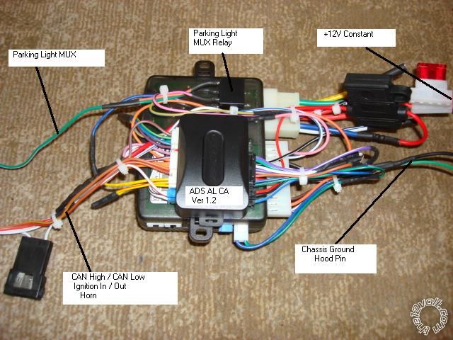
Date Posted: August 30, 2012 at 11:52 PM
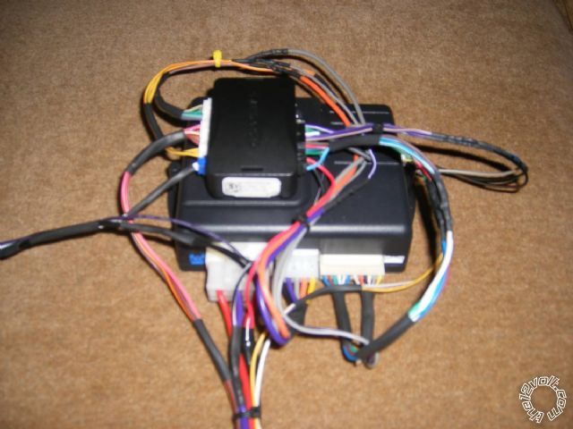
Here is my brain/FLCAN after bench prep. The bundle heading down includes the 6-ignition wires, 4-immobilzer wires, horn and parking lights. The bundle heading left includes chasis ground, siren, and door pin for the auto headlights.
Unfortunately, my cable for flashing won't arrive until next Tuesday. I may stop down at my local Best Buy and hope the installer isn't busy and see if he would be willing to flash it. Otherwise, I can still complete the install and just pull the brain next week to flash.
Any tips on antenna or shock senser mounting?
Thanks.
Posted By: kreg357
Date Posted: August 31, 2012 at 6:20 AM
Nice job!  Compact and secure. Note that you will need to see the bypasses LED briefly during vehicle programming.
Not really familiar with the AutoStart unit to help with the antenna or shock sensor. Perhaps another forum member with AutoStart experience
can provide those answers.
-------------
Soldering is fun!
Posted By: civiltoatee
Date Posted: September 02, 2012 at 4:24 PM
I have most of the wires connected (of course I will still need to wait for the flashing cable).
I could not find anything in the install instruction on the shocke senser, which has a green wire that is not connected and a green loop at the brain end of the cable looping between the green and blue wires. What should I do with the long, green, unconnected wire?
I could not figure out how to find the light blue, door pin wire in the fuse block (44-pin block, pin 22). There a lot wires here and I could not figure out how to uncover them, let alone decide which it was. Was the wire just light blue without a tracer?
Finally, how difficullt would it be to turn on one or both heated seats?
Posted By: kreg357
Date Posted: September 02, 2012 at 7:18 PM
Sorry, can't find any install guide for your system to help with the shock sensor. Still
hoping for another forum member familiar with AutoStart to assist.
If I remember correctly, you have to lift the release lever on the connector. That allows
the connector to be removed from its plug. Then you must squeeze the top portion at the
sides to release the clips that hold it to the connector and expose the wires. Of course it
is best to have the battery disconnected first. According to the wiring source listed above,
it is a plain Light Blue wire.
Not sure with the heated seats. Try this test. With the engine running, turn on the heated
seats. Turn off the engine and remove the key. Open and close the drivers door. Press Lock
on the Factory FOB. Wait 20 seconds. Press Unlock, open and close door, start van with key.
Are the heated seats on? If yes, it will be the same as the Heat & A/C. If you leave them
set before you exit the car, the remote start will get everything going where it was at shut
down. If the heated seat are off at the end of the test, then you will need a way to turn
them on after a remote start. That might be difficult on your van due to this AudioVox info :
Heated Driver Seat CANBUS
Heated Passenger Seat CANBUS
-------------
Soldering is fun!
Posted By: civiltoatee
Date Posted: September 03, 2012 at 8:14 PM
First frustration: I tried again to get into the fuse panel, but was unsucessful. As I suggested in a previous post, there is a connector at the headlight switch (pink wire) labeled on the DEI printout as 'AutoLights'. It also says after the color designation, 'ground to turn off autolights'. Could this be used in lieu of the driver's door trigger.
Second frustration: I went to hook up the chasis ground, which is a common ground for the brain (black), FLCAN and the siren. When I touched it to the gournd, the reminder chime started chiming and the headlight warning light comes on. Once it got dark, I also noticed that the dash lights also came on when I connected the ground. Both of the power fuses are pulled, so nothing should be getting power. This happens with the driver door open, but when I closed the door and touched the ground, there was no effect. This seems odd and not right, but may only happen until the unit is powered up. Any thoughts?
Thanks.
Posted By: kreg357
Date Posted: September 03, 2012 at 9:08 PM
I would try to find that Light Blue drivers door trigger wire. It is not a major issue if you always leave the Headlight switch in OFF when you exit the van ( or never remote start and remote stop the van at night ).
The weird happenings might be from the FLCAN. I believe they will stop as soon as you program it to the vehicle. Something like that happens on Chrysler CAN vehicles, too.
-------------
Soldering is fun!
Posted By: civiltoatee
Date Posted: September 04, 2012 at 7:12 AM
Thanks for the reassurance on the chiming. I will know tonight, because I will have the FLCAN flashed, programmed for W2W and ready-to-go.
I will also look at the fuse box one more time. Since we are not used to having the auto setting for the lights, I think it will be rare that we use them, even rarer when we happen to use them and then remote start, even rarer that we would use them, remote start and it is at night, and, almost inconceivable that we do all of that, let the remote start expire and not get to the car before the battery is dead.
Thanks again for all of your help. I hope to report later tonight or tomorrow that something actually works!
Posted By: racerjames76
Date Posted: September 04, 2012 at 2:15 PM
-------------
To master and control electricity is perfection. *evil laugh*
Posted By: civiltoatee
Date Posted: September 05, 2012 at 9:06 AM
Thanks to all for your comments. I did get past the chiming problem when I flashed and connected power to the brain/FLCAN.
However, I did run into a few problems. First, the flashing went smoothly. It did ask during the flashing if I would be using D2D or W2W and I selected W2W. When the flashing was complete, it still appeared to drop into the 'installation mode selection' and the unit was only flashing once, indicating, I think, that it was in D2D (even tho I had selected W2W before the flash). Therefore, I pushed the button once and it changed to two flashes. I then pushed and held the button again, supposedly then set for W2W and it went to solid green. I then did the module programing, but it came out of that with a red flashing light. Then I had to run and drop off my son somewhere and I did not want to leave it all powered up, so I pulled the fuses.
When I came back to the project and reinserted the fuses, the unit was not flashing, no lights, so I, probably errantly, assumed the unit was now 'good to go'. I then tried to program the remotes using the AS instructions, but I could not get them to program. I could always get the AS brain into the programing mode, but it never reacted as the instruction said it would to the remotes. I also could not get the AS brain to do a master reset by turning the ignition on then off and then pumping the brakes 6 times. The antenna LED was flashing at various intervals during my attempts to program and flashed in conjunction with the door opening and closing.
I plan to start over tonight by resetting the FLCAN (do I need to reflash after resetting?), redo the installation mode selection, then redo the module programming procedure and make sure I get a solid green that then goes out. I will then proceed with remote learning.
Posted By: kreg357
Date Posted: September 05, 2012 at 10:02 AM
Follow the FLCAN Install guide for a Factory Reset, bottom of Page 8. You do not need to re-flash the module but must select "Standard" mode
( 2 blinks ) and then program to the vehicle.
You should be able to program the FLCAN bypass to the vehicle first, before the AutoStart is completely programmed. Sorry, can't help with the
AutoStart, but after you get the remotes programmed, the locks should work. Do the Tach Learn process before attempting a remote start.
-------------
Soldering is fun!
Posted By: racerjames76
Date Posted: September 05, 2012 at 11:13 AM
-------------
To master and control electricity is perfection. *evil laugh*
Posted By: civiltoatee
Date Posted: September 06, 2012 at 9:51 AM
I tried again last night with no luck. I went thru a couple of different iterations, including reflashing the FLCAN with HA3 at least once. It is not clear to me when flashing the FLCAN what difference it makes when it asks what type of system is being installed: R/S only, R/S and security combo, Keyless? I am installing a R/S security combo, so I always select that option. It then asks which brand and model unit I am using and I there was a limited selection of AS for both USA and Canada. One of the options for AS is 'system not listed'. There was no model on list in either USA or Canada that exactly matched mine, so I have tried very similar model numbers and 'not listed'. Does the model number selected here have any bearing on whether the system works?
Anyway after reflashing and setting the installation mode and programming the module, all of the lights and sequences went smoothly and exactly as layed out in the FLCAN instructions. I am quite confident that there is no issue with the FLCAN.
Then it was on, again, to learning the remotes. I am able to consistently get the AS system into the programming mode, but that is about it. I tried learing both remotes about 20-times and neither was ever "learned". The only small sucess I ever had while in the programming mode was once I was able to do a master reset of the brain by depressing the brake pedal 6-times. That time the parking lights flashed 8-times indicating that it had received the instructions. However, I probably tried another ten times to duplicate the master reset procedure and never got it to work again. I must be missing something in my understanding of entering the programming mode. Small successes probably pointing to the fact that the FLCAN is working properly: 1) the system recognizes the hood pin (you must pop the hood to enter the programming mode), and 2) the system recognizes the door pin (the antenna LED flashes when the door in opened or closed).
If I had had success with consistently getting the master reset of the unit to work I would be focusing on neither of the remotes working or the antenna not working or something like that. But the master reset is very simple and is not dependent on the remotes/antenna. Since I only got that to work once, I must be doing something else wrong.
We have a shop nearby that installs AS. I will probably stop by and offer someone an Andrew Jackson to help me with the programming or help to determine if something else is amiss.
This vehicle is my wife's regular driver. Each time when I am done trying, I pull the fuses and power down the brain, because I don't want her heading out with a car that isn't fully programmed and tested. She would not like it if the alarm started going off for some unknown reason. So, when I plug the fuses back in, do I need to reset the install mode and reprogram the FLCAN or will that info hold between power downs?
Posted By: racerjames76
Date Posted: September 06, 2012 at 9:59 AM
-------------
To master and control electricity is perfection. *evil laugh*
Posted By: civiltoatee
Date Posted: September 06, 2012 at 1:19 PM
Posted By: racerjames76
Date Posted: September 06, 2012 at 1:52 PM
-------------
To master and control electricity is perfection. *evil laugh*
Posted By: civiltoatee
Date Posted: September 12, 2012 at 2:09 PM
Posted By: beegbie
Date Posted: September 16, 2012 at 7:28 AM
racerjames76 wrote:
A reset is required every time power is disconnected. Simply flash the FLCAN to Other at the first step and select hard wired method. You won't have any issues. The selection process is for DBI communication, so the FLCAN knows what signals will be coming in.
This is completely untrue.
Posted By: beegbie
Date Posted: September 16, 2012 at 7:32 AM
racerjames76 wrote:
My paycheck depends on it. I literally do 5-10 a week just resetting the bypasses. SOME cars will auto relearn the data if you start with the key the first time after reconnecting the battery.
What cars are you doing this on? What bypassed are you using? 10 of your customers cars per week are having their batteries disconnected/ go dead? Seems implausible.
Posted By: racerjames76
Date Posted: September 16, 2012 at 9:34 AM
Back when FlashLogic started NONE of their interfaces would correctly operate the data brake status. It would fail within the first few starts and leave us puzzled as to why the car wouldn't shut off. I went a year hard wiring the brake wires, until I decided that I should try the data signal again, and it had been fixed. I have used the data brake signal for the last 2 years with 0 problems, so I would say they have fixed whatever that issue was. Problem is I get paid flat rate and if a car comes back within 30 days I do not get paid for fixing it, even if the issue is not my fault.
I live in Ohio, and with the extreme heat and cold we have here many people don't realize how hard that is on their batteries. A 5 year battery is lucky to make it past 3.5-4 years here, on top of the fact noone knows maintenance free, actually requires SOME maintenance. We also work on several out of state cars where they are in the Air Force, and move here. Bringing problems from another chain store, or even our chain to me. Often because they lived in a moderate climate and had a really old battery or neglected to ever open their hood and see the mountain of sulfur/acid on their battery terminals.
Rant over, sorry for the thread jack

-------------
To master and control electricity is perfection. *evil laugh*
Posted By: civiltoatee
Date Posted: September 19, 2012 at 8:02 AM
Well, I had quite a bit of success last night. I am not exactly sure why or how, but the system ultimately settled down to the point where I was able to program the remotes. I was then able to carry out the tach learn and the vehicle remote started.
There still are some quirky things happening and it all probably relates to how the remote/system is programmed. First, the rear power lift gate does not go up or down with the designated button on the remote (either remote). Second, if I push the unlock button once, only the driver's door unlocks (so far so good), but when I push it again (supposedly progressive unlock should work), all of the doors unlock and the pass. power slider opens (very interesting). I need to spend more time with the manual now that system is generally working.
In general, I am not sure I even want to keep the alarm/security portion of the system active, but maybe I just need to get used to it. I know my wife will have a very, very low tolerance for an unexpected alarm. Right now, I have the siren disconnected, so as I learn the system, I don't have to live with the noise. I can always tell when the alarm is going off, because the lights flashing and you can hear the clicking of the relay. Is it likely that there is (are) one or two wires that if disconnected would disable the entire alarm portion of the system?
Thanks again for everyones help, especially, Kreg357.