viper 5704 / 2004 mountaineer
Printed From: the12volt.com
Forum Name: Car Security and Convenience
Forum Discription: Car Alarms, Keyless Entries, Remote Starters, Immobilizer Bypasses, Sensors, Door Locks, Window Modules, Heated Mirrors, Heated Seats, etc.
URL: https://www.the12volt.com/installbay/forum_posts.asp?tid=132392
Printed Date: April 06, 2026 at 10:31 AM
Topic: viper 5704 / 2004 mountaineer
Posted By: vinchinzo
Subject: viper 5704 / 2004 mountaineer
Date Posted: October 15, 2012 at 6:03 PM
I am going to attempt to install a Viper 5704 in my 2004 Mountaineer. I know this is a crazy task as I have never hooked up an alarm. But I can say I am pretty tech savvy and I believe I can do it heck my dad beat "you can do it" in my head as a kid and I never say cant. =) Anyway I have researched alot and found out alot but still am missing alot I really need help. The only installers in my area want a house payment to install this alarm. I know I will have to run a module to bypass the Pats system..any ideas which one? Right now when I press my stock key I really like the Illuminated entry I would love to keep it and my guess is that it is the Dome light supervision option on this alarm? I cannot find out where the (-)door trigger is? Another question I have in my brain is does the rear hatch need to be hooked up to H2/19 to trigger the alarm or will the light it turns on trigger the alarm? Another question is I want the feature where the alarm tells me the doors are open do I have to run wires to every door trigger I have 4 doors? Below is what I have figured out along with some ?? marks I would SO appreciate any help with this. Thanks alot
Main Harness (H1), 6-pin connector
H1/1 RED (+)12VDC CONSTANT INPUT-----------------Yellow (ignition) May find new source
H1/2 BLACK (-) CHASSIS GROUND-----------------------Ground to Chassis
H1/3 BROWN (+) SIREN OUTPUT-------------------------Siren
H1/4 WHITE/ BROWN PARKING LIGHT ISOLATION WIRE - PIN 87a of onboard relay------Need Help??
H1/5 WHITE PARKING LIGHT OUTPUT------------------------------------------------Brown (headlight switch)
H1/6 ORANGE (-) 500mA GROUND WHEN ARMED OUTPUT----------------- -----------------Need Help??
H2 Harness, 24-pin connector
H2/1 PINK/WHITE (-) 200mA IGNITION/FLEX RELAY CONTROL OUTPUT------------------not used??
H2/2 BLACK/ WHITE (-) NEUTRAL SAFETY INPUT------------------------------------------------Ground to Chassis
H2/3 BLUE/WHITE (-) 200mA 2ND STATUS /REAR DEFOGGER OUTPUT---------------- Need Help??
H2/4 GREEN/ BLACK (-) 200mA OEM ALARM DISARM OUTPUT-----------------------------not used
H2/5 RED / WHITE (-) 200mA TRUNK RELEASE OUTPUT-------------ORANGE / lt. green (CSM pass. rear panel)
H2/6 GREEN (-) DOOR TRIGGER INPUT (N/C* OR N/O)------------------------------------Need Help??
H2/7 BLACK / YELLOW (-) 200mA DOME LIGHT SUPERVISION OUTPUT--------same as (-) door trigger??
H2/8 BROWN / BLACK (-) 200mA HORN HONK OUTPUT------Yellow /lt. green (harness @ steering column
H2/9 DARK BLUE (-) 200mA STATUS OUTPUT-----I will need a module to bypass Pats this will go there??
H2/10 PINK (-) 200mA IGNITION 1 OUTPUT--------------------------not used when installing remote start??
H2/11 WHITE/ BLACK (-) 200mA AUX 3 OUTPUT--------------------not used
H2/12 VIOLET (+) DOOR TRIGGER INPUT----------------------------------------------BLACK/ lt. blue (drivers kick)
H2/13 WHITE/ VIOLET (-) 200mA AUX 1 OUTPUT-------------------------------not used
H2/14 VIOLET/BLACK (-) 200mA AUX 2 OUTPUT-------------------------------not used
H2/15 ORANGE / BLACK (-) 200mA AUX 4 OUTPUT-----------------------------not used
H2/16 BROWN (+) BRAKE SHUTDOWN INPUT---------------------------- Lt. Green (switch above brake pedal)
H2/17 GREY (-) HOOD PIN INPUT (N/C OR N/O)---------------------------- Hood pin wire that came with alarm
H2/18 VIOLET / YELLOW (-) 200mA STARTER OUTPUT---------------------not used??
H2/19 BLUE (-) TRUNK PIN/ INSTANT TRIGGER INPUT (N/C OR N/O)------------use for rear hatch?? how?
H2/20 GREY/BLACK (-) DIESEL WAIT TO START INPUT-------------------------------not used
H2/21 WHITE/ BLUE (-) REMOTE START/ TURBO TIMER ACTIVATION INPUT-------not used
H2/22 ORANGE (-) 200mA ACCESSORY OUTPUT--------------------------------------not used
H2/23 VIOLET/WHITE TACHOMETER INPUT--------------any wire that is not WHITE/ lt. blue (ignition coil)
H2/24 GREEN / WHITE (-) 200mA OEM ALARM ARM OUTPUT---------------------not used
Remote Start, (H3) 10-pin connector
H3/1 PINK (+) IGNITION 1 INPUT/OUTPUT---------------------------------RED / lt. green (ignition switch)
H3/2 RED / WHITE (87) FLEX RELAY +12V INPUT (30A FUSED)----------Yellow (ignition switch)
H3/3 ORANGE (+) ACCESSORY OUTPUT------------------------------------Dark GREEN/ lt. green ( ignition switch)
H3/4 VIOLET (+) STARTER OUTPUT (CAR SIDE OF THE STARTER KILL)Red (@ ignition switch starter side)
H3/5 GREEN (+) STARTER INPUT (KEY SIDE OF THE STARTER KILL)------Red (@ ignition switch keyside)
H3/6 RED IGNITION 1 +12V INPUT (30A FUSED)----------------------------Yellow (ignition switch)
H3/7 PINK/WHITE (30) FLEX RELAY OUTPUT (car side of ign, acc or starter wire)----------------not used
H3/8 PINK/BLACK (87a) FLEX RELAY INPUT (key side of ign, acc or starter wire if needed)----not used
H3/9 RED / BLACK ACCESSORY/STARTER RELAY +12V INPUT (30A FUSED)------------Yellow (ignition switch)
H3/10 NC No Connection----------------------------not used
Door Lock, 3-pin connector
1 BLUE (-) 500mA UNLOCK OUTPUT---------------------------Pink / YELLOW (drivers kick door harness Type B)
2 EMPTY NOT USED-----------not used
3 GREEN (-) 500mA LOCK OUTPUT----------------------------Pink/lt. green(drivers kick door harness Type B)
after this is complete it would be a great guide for someone else =)
-------------
When in doubt....kick it!
Replies:
Posted By: vinchinzo
Date Posted: October 15, 2012 at 6:07 PM
2004 Mercury Mountaineer Base V8 4.6 liter
Viper 5704 Responder LC3 SuperCode SST 2-Way Security and Remote Start System5704V
-------------
When in doubt....kick it!
Posted By: kreg357
Date Posted: October 15, 2012 at 7:18 PM
Looking good so far, Vince! Here are some updates...
Domelight supervision may not be required. Check to see if the interior lights come on when you unlock the doors
with the Factory FOB. That will also happen with the Viper's unlock command.
You will need a bypass module. You will need two working, non-clone, keys to program the bypass module. Saw a
DEI 1100F on EBay listed as NEW and N.I.B. for $15. They work well on Fords PATS systems. Other popular bypass
modules are the DEI PKALL and the Fortin Key-OverRide-All.
I don't see any wire guide listings for the 4 individual door pins.
You only need to connect one - Door Trigger (-) or Door Trigger (+) - not both.
Main Harness (H1), 6-pin connector
H1/1 RED (+)12VDC CONSTANT INPUT-----------------Yellow (ignition) May find new source
H1/2 BLACK (-) CHASSIS GROUND-----------------------Ground to Chassis
H1/3 BROWN (+) SIREN OUTPUT-------------------------Siren
H1/4 WHITE/ BROWN PARKING LIGHT ISOLATION WIRE - PIN 87a of onboard relay------Not Used
H1/5 WHITE PARKING LIGHT OUTPUT-----------------------Brown (headlight switch) ** Set Viper jumper/fuse to (+)
H1/6 ORANGE (-) 500mA GROUND WHEN ARMED OUTPUT----------------- -------------- Not Used
H2 Harness, 24-pin connector
H2/1 PINK/WHITE (-) 200mA IGNITION/FLEX RELAY CONTROL OUTPUT----------------- Not Used
H2/2 BLACK/ WHITE (-) NEUTRAL SAFETY INPUT------------------------------------ Ground to Chassis * w/auto trans
H2/3 BLUE/WHITE (-) 200mA 2ND STATUS /REAR DEFOGGER OUTPUT---------------- Not used
H2/4 GREEN/ BLACK (-) 200mA OEM ALARM DISARM OUTPUT-----------------------------not used
H2/5 RED / WHITE (-) 200mA TRUNK RELEASE OUTPUT---- ORANGE / lt. green (CSM pass. rear panel) * Need Relay for (-) to (+)
H2/6 GREEN (-) DOOR TRIGGER INPUT (N/C* OR N/O)-- yellow/black - N.C. driver kick, door harness *set Viper to N.C.
H2/7 BLACK / YELLOW (-) 200mA DOME LIGHT SUPERVISION OUTPUT--------same as (-) door trigger??
H2/8 BROWN / BLACK (-) 200mA HORN HONK OUTPUT------Yellow /lt. green (harness @ steering column
H2/9 DARK BLUE (-) 200mA STATUS OUTPUT----- To bypass module = GWR
H2/10 PINK (-) 200mA IGNITION 1 OUTPUT--------------------------not used
H2/11 WHITE/ BLACK (-) 200mA AUX 3 OUTPUT--------------------not used
H2/12 VIOLET (+) DOOR TRIGGER INPUT----------------------------------------------BLACK/ lt. blue (drivers kick)
H2/13 WHITE/ VIOLET (-) 200mA AUX 1 OUTPUT-------------------------------not used
H2/14 VIOLET/BLACK (-) 200mA AUX 2 OUTPUT-------------------------------not used
H2/15 ORANGE / BLACK (-) 200mA AUX 4 OUTPUT-----------------------------not used
H2/16 BROWN (+) BRAKE SHUTDOWN INPUT---------------------------- Lt. Green (switch above brake pedal)
H2/17 GREY (-) HOOD PIN INPUT (N/C OR N/O)---------------------------- Hood pin wire that came with alarm
H2/18 VIOLET / YELLOW (-) 200mA STARTER OUTPUT---------------------not used
H2/19 BLUE (-) TRUNK PIN/ INSTANT TRIGGER INPUT (N/C OR N/O)-- WHITE/ purple - N.C. driver kick, harness to rear *set Viper to N.C.
H2/20 GREY/BLACK (-) DIESEL WAIT TO START INPUT-------------------------------not used
H2/21 WHITE/ BLUE (-) REMOTE START/ TURBO TIMER ACTIVATION INPUT-------not used
H2/22 ORANGE (-) 200mA ACCESSORY OUTPUT--------------------------------------not used
H2/23 VIOLET/WHITE TACHOMETER INPUT--------------any wire that is not WHITE/ lt. blue (ignition coil)
H2/24 GREEN / WHITE (-) 200mA OEM ALARM ARM OUTPUT---------------------not used
Remote Start, (H3) 10-pin connector
H3/1 PINK (+) IGNITION 1 INPUT/OUTPUT---------------------------------RED / lt. green (ignition switch)
H3/2 RED / WHITE (87) FLEX RELAY +12V INPUT (30A FUSED)----------Yellow (ignition switch)
H3/3 ORANGE (+) ACCESSORY OUTPUT------------------------------------Dark GREEN/ lt. green ( ignition switch)
H3/4 VIOLET (+) STARTER OUTPUT (CAR SIDE OF THE STARTER KILL)Red (@ ignition switch starter side)
H3/5 GREEN (+) STARTER INPUT (KEY SIDE OF THE STARTER KILL)------Red (@ ignition switch keyside)
H3/6 RED IGNITION 1 +12V INPUT (30A FUSED)----------------------------Yellow (ignition switch)
H3/7 PINK/WHITE (30) FLEX RELAY OUTPUT (car side of ign, acc or starter wire)----------------not used
H3/8 PINK/BLACK (87a) FLEX RELAY INPUT (key side of ign, acc or starter wire if needed)----not used
H3/9 RED / BLACK ACCESSORY/STARTER RELAY +12V INPUT (30A FUSED)------------Yellow (ignition switch)
H3/10 NC No Connection----------------------------not used
Door Lock, 3-pin connector
1 BLUE (-) 500mA UNLOCK OUTPUT---------------------------Pink / YELLOW (drivers kick door harness Type B)
2 EMPTY NOT USED-----------not used
3 GREEN (-) 500mA LOCK OUTPUT----------------------------Pink/lt. green(drivers kick door harness Type B) ------------- Soldering is fun!
Posted By: smokeman1
Date Posted: October 15, 2012 at 7:24 PM
https://www.bulldogsecurity.com/bdnew/vehiclewiringdiagrams.asp
Link to wiring guide. Wires listed are a guide and may not match your vehicle. Use a DMM to find and test the wires you need. The Viper 5701 install manual in the downloads section has a section on finding and testing for the wires you need.
Fortin Key override-all is a good bypass to use. Easy to use but you need two orginal keys to program it. ------------- When all else fails, Read the Instructions
Support the12volt.com Make a Donation
Posted By: smokeman1
Date Posted: October 15, 2012 at 7:26 PM
Once again Kreg, ya got the jump on me......LOL
-------------
When all else fails, Read the Instructions
Support the12volt.com Make a Donation
Posted By: kreg357
Date Posted: October 15, 2012 at 7:36 PM
A couple more thoughts.
You should solder all connections.
Use heatshrink tube where possible and quality electric tape ( Scotch Super 33+ ) everywhere else.
You will need a Digital Multi Meter to locate, test and verify the vehicle wires. A low current,
computer safe LED test probe can be used for most wires. The PATS wires are not DMM testable, go
by the install guide supplied with the bypass for wire identification / location / color, etc.
Locate / position the Viper in a good spot and then group the wires going to the same general area.
Cut eact wire to length and then solder / insulate. Beware of heat and chaffing in your wire runs.
Use plenty of split-loom, tie wraps and/or black tape to keep thing neat & looking factory.
You will need to change sevaral programming options on the Viper. This can be done with the remotes
but takes some time getting familiar with moving thru the menus. Have a few asprins ready ( or beers ).
Plan on spending a full day on the install. You only want to do it once and have it last for years. ------------- Soldering is fun!
Posted By: vinchinzo
Date Posted: October 15, 2012 at 10:20 PM
Thanks so much! I am shocked at how fast I got a response! Woot woot!! So now I have ran into another problem...I only have one key grrrr...I know I can get a clone key for like 50 but that wont work. What do I do? Dealership? Bet that's alot of money there for a key. And one more thing...you said You only need to connect one - Door Trigger (-) or Door Trigger (+) - not both So do I only connect one of these?
H2/6 GREEN (-) DOOR TRIGGER INPUT (N/C* OR N/O)-- yellow/black - N.C. driver kick, door harness *set Viper to N.C.
H2/12 VIOLET (+) DOOR TRIGGER INPUT----------------------------------------------BLACK/ lt. blue (drivers kick)
I'm guessing If so I should use the (-)?
Thanks so much for the help you rock!
-------------
When in doubt....kick it!
Posted By: shortcircuit161
Date Posted: October 15, 2012 at 10:57 PM
With only one key, you can buy a DB-ALL from Directed (DEI) or the ADS-AL CA from idatalink. They are more pricey (about $45-$60) but have the ability to "clone" the single key transponder info to allow the remote start to work.
idatalink requires you to have an account with them or know someone that has an account to flash the module.
DEI doesn't require an account to flash the DB-ALL.
-------------
Posted By: flobee4
Date Posted: October 15, 2012 at 11:09 PM
I had an explorer of that generation. I used the blue/black (+) in the drivers kick panel. It also detects the hatch so there is no need to use the vipers trunk trigger. This wire will continue to show a signal when you close the doors because of the delay in the domelight turning off. In the vipers programming menus there is an option called door trigger error on/off. Turn that option to off.
The Explorer dome light does not come on automatically with unlock. So if you want that feature you will need to wire it up from the Vipers Dome light supervision output. There are 2 options for this. the first is to use a relay on the dome light supervision output of the Viper to convert the negative signal coming out of that wire to a positive. Then you can hook up that positive output to the same BLACK/ blue door trigger wire. The other option is that there is a negative domelight supervision wire at the headlight switch. If you roll the dashboard light dimmer switch all the way up, you will feel it click into a position that turns on the domelight. Pop out the headlight switch from the dashboard and using a meter test for a wire that goes negative when the dimmer switch is rolled all the way up and losing negative when the switch is rolled down. To test you put your red probe on a known positive source and probe the back of the switch with the black probe. Sorry I don't have a color for you. Also a note, while the car is running or remote started the puddle lights on the mirrors won't come on, thats a Ford thing. if the car is sitting there not running and you hit unlock they will come on.
Also if you are doing the rear hatch release, its a positive wire and most diagrams will tell you its at the roof inside the car at the hatch. I believe you can find it in the drivers side rear door running board, same color as listed in the wiring diagrams.
If you only have one key, then I probably would get the clone key and put it in a 556U key in a box solution and you will be good to go. There are other ways to do it with only one key, but you would have to be a registered professional with the companies that offer these solutions. Plus have their programming cables. Your cheapest solution is the clone key inside a 556u
Posted By: vinchinzo
Date Posted: October 16, 2012 at 6:24 PM
Thanks everyone for your help you guys have been awesome! Here is a update of my plans lol I have looked into the One transponder key issue and I've decided to let this local Locksmith guy make me a Key for 50 bucks. He assures me it wont be a clone it will be a second programmed key. I think its a good idea cuz if I loose my one key I will so be screwed! lol So in doing that I'm gonna go with the Dei Xpresskit PKALL. Here is my final updated install tech sheet please look it over and see if I'm missing anything or anything is wrong.
Main Harness (H1), 6-pin connector
H1/1 RED (+)12VDC CONSTANT INPUT-----------------Yellow (ignition)
H1/2 BLACK (-) CHASSIS GROUND-----------------------Ground to Chassis
H1/3 BROWN (+) SIREN OUTPUT-------------------------Siren
H1/4 WHITE/ BROWN PARKING LIGHT ISOLATION WIRE - PIN 87a of onboard relay------Not Used
H1/5 WHITE PARKING LIGHT OUTPUT-----------------------Brown (headlight switch) ** Set Viper jumper/fuse to (+)
H1/6 ORANGE (-) 500mA GROUND WHEN ARMED OUTPUT----------------- -------------- Not Used
H2 Harness, 24-pin connector
H2/1 PINK/WHITE (-) 200mA IGNITION/FLEX RELAY CONTROL OUTPUT----------------- Not Used
H2/2 BLACK/ WHITE (-) NEUTRAL SAFETY INPUT------------------------------------ Ground to Chassis *w/auto trans
H2/3 BLUE/WHITE (-) 200mA 2ND STATUS /REAR DEFOGGER OUTPUT---------------- Not used
H2/4 GREEN/ BLACK (-) 200mA OEM ALARM DISARM OUTPUT-----------------------------not used
H2/5 RED / WHITE (-) 200mA TRUNK RELEASE OUTPUT---- ORANGE / lt. green (CSM pass. rear panel) *Need Relay for (-) to (+)
H2/6 GREEN (-) DOOR TRIGGER INPUT (N/C* OR N/O)-- yellow/black (driver kick, door harness) *set Viper to N.C.
H2/7 BLACK / YELLOW (-) 200mA DOME LIGHT SUPERVISION OUTPUT--------BLACK/ lt. blue (drivers kick) *Need Relay for (-) to (+)
H2/8 BROWN / BLACK (-) 200mA HORN HONK OUTPUT------Yellow /lt. green (harness @ steering column
H2/9 DARK BLUE (-) 200mA STATUS OUTPUT----- To PKALL bypass module = GWR (Blue/Wht wire on connector 1 of PKALL)
H2/10 PINK (-) 200mA IGNITION 1 OUTPUT--------------------------not used
H2/11 WHITE/ BLACK (-) 200mA AUX 3 OUTPUT--------------------not used
H2/12 VIOLET (+) DOOR TRIGGER INPUT----------------------------------------------BLACK/ lt. blue (drivers kick)
H2/13 WHITE/ VIOLET (-) 200mA AUX 1 OUTPUT-------------------------------not used
H2/14 VIOLET/BLACK (-) 200mA AUX 2 OUTPUT-------------------------------not used
H2/15 ORANGE / BLACK (-) 200mA AUX 4 OUTPUT-----------------------------not used
H2/16 BROWN (+) BRAKE SHUTDOWN INPUT---------------------------- Lt. Green (switch above brake pedal)
H2/17 GREY (-) HOOD PIN INPUT (N/C OR N/O)---------------------------- Hood pin wire that came with alarm
H2/18 VIOLET / YELLOW (-) 200mA STARTER OUTPUT---------------------not used
H2/19 BLUE (-) TRUNK PIN/ INSTANT TRIGGER INPUT (N/C OR N/O)-- WHITE/ purple - N.C. driver kick, harness to rear *set Viper to N.C.
H2/20 GREY/BLACK (-) DIESEL WAIT TO START INPUT-------------------------------not used
H2/21 WHITE/ BLUE (-) REMOTE START/ TURBO TIMER ACTIVATION INPUT-------not used
H2/22 ORANGE (-) 200mA ACCESSORY OUTPUT--------------------------------------not used
H2/23 VIOLET/WHITE TACHOMETER INPUT--------------any wire that is not WHITE/ lt. blue (ignition coil)
H2/24 GREEN / WHITE (-) 200mA OEM ALARM ARM OUTPUT---------------------not used
Remote Start, (H3) 10-pin connector
H3/1 PINK (+) IGNITION 1 INPUT/OUTPUT---------------------------------RED / lt. green (ignition switch)
H3/2 RED / WHITE (87) FLEX RELAY +12V INPUT (30A FUSED)----------Yellow (ignition switch)
H3/3 ORANGE (+) ACCESSORY OUTPUT------------------------------------Dark GREEN/ lt. green (ignition switch)
H3/4 VIOLET (+) STARTER OUTPUT (CAR SIDE OF THE STARTER KILL)Red (@ ignition switch starter side)
H3/5 GREEN (+) STARTER INPUT (KEY SIDE OF THE STARTER KILL)------Red (@ ignition switch keyside)
H3/6 RED IGNITION 1 +12V INPUT (30A FUSED)----------------------------Yellow (ignition switch)
H3/7 PINK/WHITE (30) FLEX RELAY OUTPUT (car side of ign, acc or starter wire)----------------not used
H3/8 PINK/BLACK (87a) FLEX RELAY INPUT (key side of ign, acc or starter wire if needed)----not used
H3/9 RED / BLACK ACCESSORY/STARTER RELAY +12V INPUT (30A FUSED)------------Yellow (ignition switch)
H3/10 NC No Connection----------------------------not used
Door Lock, 3-pin connector
1 BLUE (-) 500mA UNLOCK OUTPUT---------------------------Pink / YELLOW (drivers kick door harness Type B)
2 EMPTY NOT USED-----------not used
3 GREEN (-) 500mA LOCK OUTPUT----------------------------Pink/lt. green(drivers kick door harness Type B)
XPRESS PKALL MODULE
Connector 1
D2D---------------------------------To D2D on Viper 5704
Connector 2
PURPLE / wht RX(data in) -------------Gray/orange (@ IMMOBILIZER NEAR KEY BARREL Pin 4 closes to key)
Yellow/blk TX(data out)-------------WHITE/ lt. green (@ IMMOBILIZER NEAR KEY BARREL Pin 3)
Blue/wht----------------------------To H2/9 DARK BLUE (-) 200mA STATUS OUTPUT- of Viper 5704
Green-------------------------------not used
Pink--------------------------------RED / lt. green (ignition switch) Do I hook this up and leave H3/1 of the alarm unconnected???
Black-------------------------------not used
Connector 3 & 4 (not used)
My understanding of the two relays I will need to hook up for 1. the rear hatch to use trunk trigger and 2. for dome light supervision should be hooked up the same way?
For Rear hatch
#775 relay
Pin 85 black-----------------------to H2/5 RED / WHITE (-) 200mA TRUNK RELEASE OUTPUT of Viper 5704
Pin 86/30 white and blue-----------wired to a 12v constant
Pin 87a Red------------------------not used
Pin 87 Yellow-----------------------to ORANGE / lt. green (CSM pass. rear panel)
Dome light supervision
#775 relay
Pin 85 black-----------------------H2/7 BLACK / YELLOW (-) 200mA DOME LIGHT SUPERVISION OUTPUT of Viper 5704
Pin 86/30 white and blue-----------wired to a 12v constant
Pin 87a Red------------------------not used
Pin 87 Yellow-----------------------to BLACK/ lt. blue (drivers kick)
The only question I have now is the only 12v constant that I have been using it the Yellow wire at the ignition should I use or maybe run a new source from the battery to run some of these? and Can I place the two relays back to back by where ever I decide to place the Brain of the alarm?
I think this is gonna be the complete setup how does it look? Wowsers Im kinda skeered lol
-------------
When in doubt....kick it!
Posted By: kreg357
Date Posted: October 16, 2012 at 6:40 PM
Two, non-clone keys is a good idea. Always nice to have a spare.
H3/2 connection is not necessary if you are not using the Flex Relay output ( H3/7 ).
You don't need to connect both the Vipers (+) and the (-) Door Trigger wires. Use only the (-) trigger and save the (+) for the Dome light Supervision.
The Viper's H3/1 Ignition must be run to the vehicles Ignition wire. The easiest way is to just connect the PKALL's Pink wire to the H3/1 Pink and continue the H3/1 Pink to the vehicles ignition harness.
Trunk Release and Dome light relays are good. Just insulate the unused 87A lead and put a 10 Amp fuse on the +12V constant input wires. ------------- Soldering is fun!
Posted By: flobee4
Date Posted: October 17, 2012 at 12:02 AM
you can't just connect to the yellow/black door trigger wire in the drivers kick panel. That would only detect the drivers door. You would need to connect to all the door triggers and diode isolate them.
Left Front Door Trigger Yellow/Black Open Driver's Kick Panel
Right Front Door Trigger Gray/Red Open Passenger's Kick Panel
Left Rear Door Trigger Lt.GREEN/ YELLOW Open Driver's Kick Panel
Right Rear Door Trigger Pink/Lt.Blue Open In Right Rear Door Harness
Posted By: vinchinzo
Date Posted: October 17, 2012 at 9:48 AM
Yea Kreg I thought the same thing about getting another key all I need is to have a ride with a pumped alarm towed to a dealer to make new keys if I loose the only transponder key I got lol So now I'm gonna need to wire all door triggers??? Diodes? Just when I thought I had it all figured out lol How does all that work? I've read some people say it is necessary and others say its not? Also I have decided that I'm gonna upgrade a little bit for cheap and get a Piezo siren, another shock sensor, and the glass break sensor. After and if I can install this and program it all next spring I will install the window modules..but Im gonna tackle that later on after I see if my man skills can do this install lol. My first alarm install is gonna be a doozey im sure! Kregg I will be needing plenty of them asprins..NAH Ima go with the beers! LOL
-------------
When in doubt....kick it!
Posted By: vinchinzo
Date Posted: October 17, 2012 at 9:53 AM
My understanding of door triggers and isolating with diodes is its usually only needed on GM? And even then you don't have to run 4 triggers just two? Does this apply to my Mercury Mountaineer?
-------------
When in doubt....kick it!
Posted By: flobee4
Date Posted: October 17, 2012 at 10:17 AM
If you only hook up to the yellow/black wire you are only sensing the drivers door. Anytime you you hook up 1 wire to multiple wires you need to isolate feedback. To stop that feedback you use diodes.
Or just use the purple wire off the viper to the blue/black dome light wire, and call it a day. The blue/black also gets signal when the hatch or the hatch glass is opened. So, no need to use the vipers blue trunk trigger wire. oh, if you do use this wire you cannot disable the dome light using the dimmer switch otherwise your viper will not sense a door opening, since the domelight is disabled.
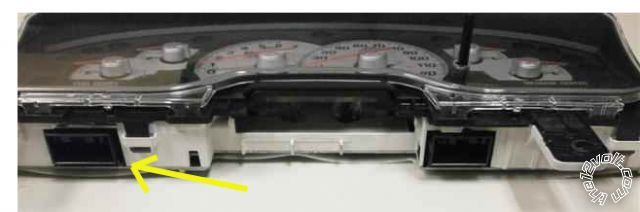
Just thought of another trick. There should be a light blue/white wire for standard negative door trigger located in the bottom left connector plugged into the cluster. You would connect your vipers green wire directly to this wire. This light blue/white wire feeds the "door ajar" signal in the cluster. To see the connector in the lower left of the cluster you do not need to remove the cluster, just the trim. While the cluster is still in its spot, just look at the bottom left, you will see a plug sticking down. You might need to remove the cluster to make your connections, but not to be able to see the connector I'm talking about. This wire has NO domelight delay and is NOT affected if you disable the domelight. It also senses all doors, hatch, and hatch glass. If you use the light blue/white vire for a negative trigger you will still need to use the BLACK/ blue(+) wire for dome supervision, using a relay of course.
Posted By: flobee4
Date Posted: October 17, 2012 at 10:36 AM
the arrow is pointing to where the Lt. Blue/white wire should be located.
Posted By: vinchinzo
Date Posted: October 17, 2012 at 6:41 PM
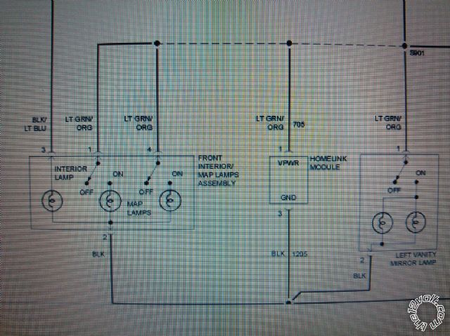 This is a picture of the schematic for the dome light I see the BLACK/ lt.blue (+) wire wouldn't the Lt.GREEN/ orange be the (-)? Something I could use for the dome light supervision without a relay? ------------- When in doubt....kick it!
Posted By: vinchinzo
Date Posted: October 17, 2012 at 7:01 PM
Dude scratch that last comment I totally had a brain fart them are the 12v constant wires powering the switches on the dome light lol duh
-------------
When in doubt....kick it!
Posted By: vinchinzo
Date Posted: October 17, 2012 at 7:50 PM
I guess the only thing I'm worried about now is the door triggers and the dome light supervision. Also Will having a delayed illuminated exit mess with arming the alarm? My mountaineer has illuminated exit.
-------------
When in doubt....kick it!
Posted By: flobee4
Date Posted: October 17, 2012 at 10:29 PM
Did you not read what I wrote... If you do use the BLACK/ blue wire as your Positive Door Trigger then it WILL read the dome light delay. But, to compensate for it, you need to turn OFF the Door Error chirp. Its Menu 2 Option 4 on the 5704. I posted that a few posts ago on the first page. Are you reading the directions??? Do you have the proper testing equipment(DVM)??? Do you plan on testing the wires or just going off the color wires we've listed and helped you with? I've given you 3 ways to do the door triggers... You choose what the best option is for you. Dig in your truck with you DVM look for the wires and test and tag.
Posted By: vinchinzo
Date Posted: October 18, 2012 at 5:50 AM
Thanks alot flobee I was just stuck on which option to use..I am gonna test all connections first because even tho the wire codes are listed heck ya just never know better to be safe then sorry. I believe im gonna try to use the blue/white door ajar wire you was talking about. I have alot of kids and I don't want to be able to arm the alarm with a door open. I think if I use the BLACK/ blue wire and set the door trigger error off then the alarm will set and I wont know the doors open right? So my understanding is if I can locate the door ajar wire then it will only read the actual door triggers not the dome light and The alarm will set and work like it should even with the dome delay and if a doors open it will still give me a status message on my LCD? I'm getting the alarm and all the goodies Friday I'm gonna try it all out sometime this weekend I will post how it went after I'm done.
-------------
When in doubt....kick it!
Posted By: flobee4
Date Posted: October 18, 2012 at 7:20 AM
Yes, the light blue/white wire will achieve what you are looking to do. Also, Your dome light supervision relay to the BLACK/ blue wire will still be needed if you use the light blue/white wire. The way you have the relay listed in the previous post is correct, so you are good to go with that too.
Good luck with your install :)
Posted By: vinchinzo
Date Posted: October 18, 2012 at 7:41 AM
Thanks again bro! I was bored so I went and took a look at that wire we was talking about and yea its not there. So I looked up the schematic and I see there is a orange data line coming from the VSM that feeds the digital message center in my cluster. So what do you think about this...I tap all my triggers diode them all into one wire right from the VSM in the right rear quarter run that one wire down the passenger side then to the alarm? That may make it easier considering all my wires for every trigger is right there? But this raises another question..Do I use the Wht/Violet rear hatch/tailgate into this mix are just run that wire to the blue (-) trunk pin input on the alarm? Oh and will I need to run the door triggers into a relay? I know on older models the bcm would go to sleep and cause false alarms and the relay fix worked well? 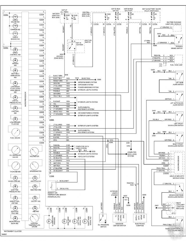 ------------- When in doubt....kick it!
Posted By: flobee4
Date Posted: October 18, 2012 at 8:03 AM
I can't read that... But it not the orange data line wire. You might want to look to see if you find the schematic for the cluster rather than that schematic. Anyway, to get to that VSM, its a royal pain in the butt. you will have to take apart the rear seat belt, the weather strip around the rear door near the rear panel, theres hidden clips that rotate under there, the trim near the rear hatch, and ultimately the whole rear panel around the rear window.
I would personally remove the 2 7mm bolts from the top of the cluster trim, unscrew the steering wheel shroud, and pop out the cluster trim. That'll take you 15 minutes tops. Then you can look for the light blue/white wire in the bottom plug of the cluster in which I posted a picture of earlier.
But if you want to use the door triggers instead, I listed on page 2 of this thread the wire colors and alternate locations for these wires besides the VSM(I think its actually called CCM). You should only need to diode isolate them. the diodes white band away from the vipers brain. trunk trigger doesn't need a diode since its only 1 wire. Don't forget to set your Vipers programmable options to the correct door and trunk trigger type.
Posted By: flobee4
Date Posted: October 18, 2012 at 8:27 AM
I just uploaded the Cluster wiring diagram for the truck I had to the download section on this site. It was a 2002 Explorer. Look under Instrument cluster wiring in your service manual. In my schematic on the right side it says #57 is the door ajar light. Then to the left next to one of the symbols for a light bulb there is a 57 next to it. Notice the LB/wh connected to it. thats the light blue/white wire you need. Check to see if its there on a 04.
02 Explorer Cluster Wiring
Posted By: vinchinzo
Date Posted: October 18, 2012 at 9:03 AM
Yea I think the 2002 still had what they called the gem/bcm whatever.. the 2004 went to a Vsm. The gem used to be by the radio now there is no gem. The only diagram i can find is this one and it still shows the orange data line running the door ajar. 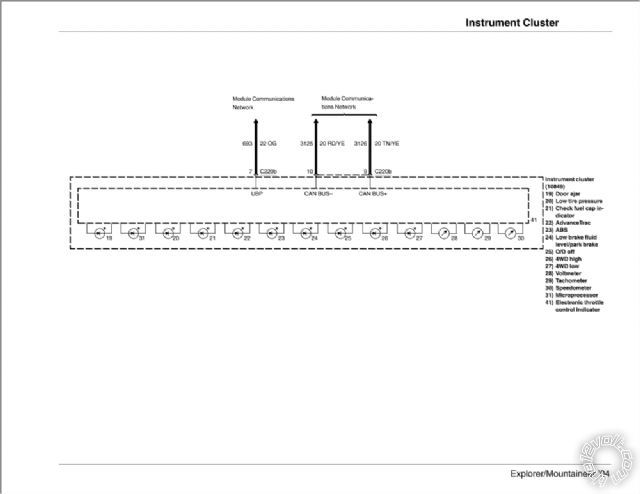 ------------- When in doubt....kick it!
Posted By: vinchinzo
Date Posted: October 18, 2012 at 9:09 AM
I know them are hard to read here so I did what you did and uploaded it heres the link https://www.the12volt.com/installbay/file.asp?ID=546
-------------
When in doubt....kick it!
Posted By: vinchinzo
Date Posted: October 18, 2012 at 10:05 AM
Man its sunny out and like 70 degrees I think im gonna take my multimeter on out there and find this door trigger wire lol I will let ya know if its there for sure =)
-------------
When in doubt....kick it!
Posted By: vinchinzo
Date Posted: October 18, 2012 at 11:20 AM
Yea thats a negative there is no whit/blue..I was so stoked about that wire to lol I did find this in the free library database explaining that orange wire.
Door Ajar Warning Indicator (Base Cluster)
The door ajar switches provide a ground signal to the vehicle security module. The vehicle security module, upon receipt of the door ajar ground data, supplies a door ajar status message to the instrument cluster through the UBP communication network. The instrument cluster monitors the door ajar status and commands the door ajar indicator on or off according to the door ajar status message.
I don't know about what kinda of signal comes from that orange wire I would think it would have to be a positive signal with data because not only does my cluster show door ajar but it will also say lift-gate open. I don't think I will be able to use that wire. I believe Im gonna just isolate and use each door trigger. I wish the alarm was here because I already got my whole dash apart out there right now lol Maybe I just wont drive it because the alarm is coming tomorrow.
-------------
When in doubt....kick it!
Posted By: vinchinzo
Date Posted: October 18, 2012 at 1:15 PM
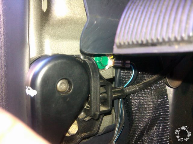
I have been out there messing around testing wires just to be a step ahead and I ran into a problem trying to find the hatch release ORANGE / lt. grn wire. I looked for it in the rear driver runner wasn't there, looked for it in the rear quarter and couldn't find it. But I did find this wire it is purple / YELLOW at the Vsm I hooked up the DM put the black to ground and the red to this wire it was at 0 then I popped the hatch with my factory fob and the meter went up to around 12v like 11.7 jumped around and went down. I tried it several times so I believe this is the hatch release right? I am gonna go ahead and run all my door triggers and my hatch release from here it wasnt to bad to get to just pry the panel over enough to reach in and unplug the harness and you can stand and tap in =) 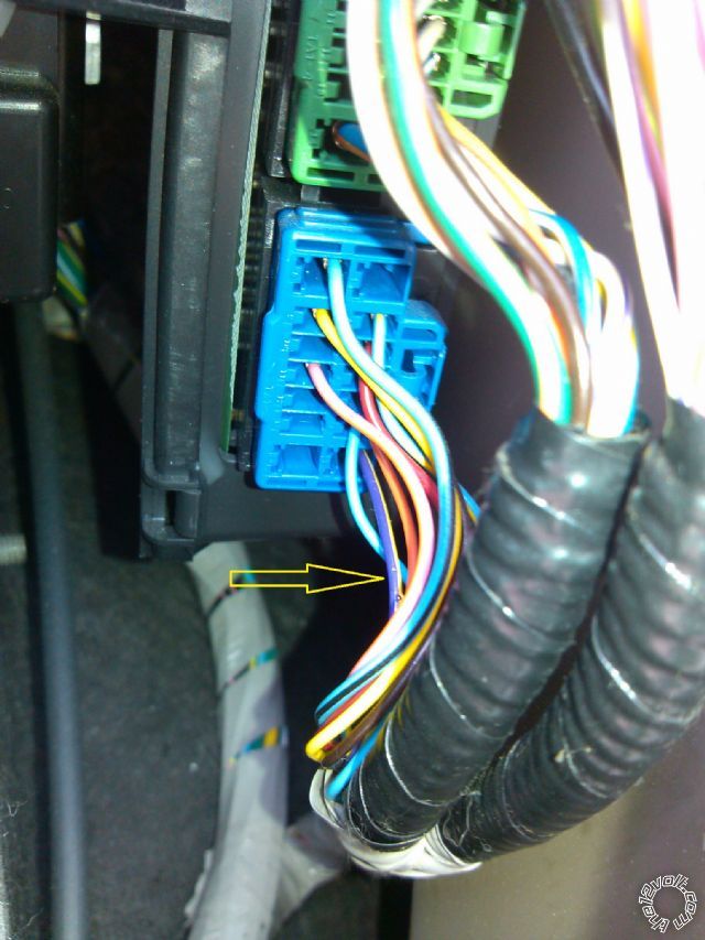
There are three harnesses just incase someone else reads this and needs help. The top one holds all the door triggers and the very bottom one has the hatch release. =) ------------- When in doubt....kick it!
Posted By: flobee4
Date Posted: October 18, 2012 at 6:25 PM
Ya, even though the 02 and 04 look exactly the same, they are indeed different. All those lights listed in the diagram you uploaded are turned on by computer signals. Can't tap into them like an 02. Sorry to mislead you there. Also that module behind the panel where you posted the picture, on an 02 all the plugs are facing the floor instead of the side. Your year looks alot easier to get to the wires there. As for the hatch release, some diagrams do say that the wire may be purple / YELLOW. SO as long as it tested when the trunk release button on the remote or button in the back hatch was hit, you will be good to go.
Posted By: vinchinzo
Date Posted: October 18, 2012 at 7:38 PM
Thanks alot brother you been of great help! I have prepped as much as possible now ima go for it lol I've never installed an alarm before so I been real weary. I'm gonna make a pictorial for others aslong as I'm successful. My only real worry now is programming everything but I think I can do it :)
-------------
When in doubt....kick it!
Posted By: vinchinzo
Date Posted: October 19, 2012 at 10:54 AM
I have a huge question?? I was out there testing my door triggers so let me make sure I got this right. I set my MM to DC hooked the black to ground then the red to the door trigger opened the door and it shows 12v shut the door and it goes back to 0??? All them door triggers are positive triggers right? My only guess is if I hook them to the H2/6 GREEN (-) DOOR TRIGGER INPUT (N/C* OR N/O) and set it to NC the NC compensates for this? Or am I suppose to run these to H2/12 VIOLET (+) DOOR TRIGGER INPUT??
-------------
When in doubt....kick it!
Posted By: flobee4
Date Posted: October 19, 2012 at 5:10 PM
Those triggers are ground when closed and open when when the doors are opened. The way I would check that is to put the red probe on a known 12volt source and probe your door triggers with the black.
Still supposed to use green (-) door trigger and change it from default value.
Posted By: vinchinzo
Date Posted: October 19, 2012 at 9:43 PM
They are indeed negative Kregg helped me out earlier =) Tomorrows the big day lol I hope it goes good here's a pic of my setup I'm all ready. The only wire I haven't found yet is the hatch release and that defrost wire I may just leave the defrost out but it would be nice to walk out to a warm defrosted ride in the winter =)
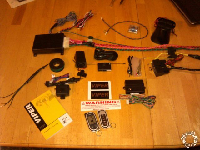 ------------- When in doubt....kick it!
Posted By: kreg357
Date Posted: October 20, 2012 at 6:29 AM
2004 Mountaineer info from Audiovox. This info conflicts with others, as it lists the signals at (+), while most
list the triggers as N.C. (-), but it does give wire colors & pin locations. The DMM is your only friend.
LF Latch YELLOW/BLACK (+) AT CSM MODULE Pin 1
RF Latch GRAY/RED (+) AT CSM MODULE Pin 2
LR Latch LIGHT GREEN/ YELLOW (+) AT CSM MODULE Pin 9
RR Latch PINK/LIGHT BLUE (+) AT CSM MODULE Pin 7
Trunk Trigger WHITE/ VIOLET (+) AT CSM MODULE Pin 12
Hood Trigger TAN/LIGHT GREEN (+) AT CSM MODULE Pin 11
2004 Mountaineer info from Omega
Rear Defrost BROWN / LT.BLUE (+) AT REAR DEFROST SWITCH
No additional info on this wire. You will need to locate the wire and test it with the DMM to see if it is a "latched"
output or a single pulse output. Either way you will need a relay to convert the Vipers (-) output to the (+) output
this wire requires. Also depending on the wires thickness ( current draw ) you might need to use a 30/40 amp rated
relay and fuse accordingly.
Trunk Release VIOLET / YELLOW (-) AT TRUNK RELEASE SWITCH
More conflicting info. As alway test & verify with a DMM. On a 2003 Explorer, I found that the rear hatch was
unlocked with the same unlock wire used for the doors. The Violet / YELLOW wire you located at the CSM, and took a photo
of, seemed to be correct. ------------- Soldering is fun!
Posted By: vinchinzo
Date Posted: October 20, 2012 at 7:43 AM
Oh boy lol Im bout to get started I got to run and get a few little things first. About them door triggers I tested them yesterday with the dmm like you guys was saying I set to 20dcv red probe on 12v and the black probe on the door trigger/ With the door shut it read 12v with it open it went down. This would mean it is a negative correct? or is their anyway that could be wrong? im uploading the defogger schematic take a look at it if ya want Im thinking about using the try/lt blu that is before the relay and setting to pulsed or the org / YELLOW? the only brn/lt blue I see is the actual wire going to the defrost grid on the window. I could just leave the defrost out but I really need to figure out the door trigger thing lol
-------------
When in doubt....kick it!
Posted By: vinchinzo
Date Posted: October 20, 2012 at 7:49 AM
04 Defrost Schematic Heres the schematic im a little good at these things but you may be alot better lol. My plan is to either use the gry/lt blu or the org/yel coming from the Temperature control module. The gry blue leads to a microproccessor of some sort and org/yell comes from that on to the defrost relay...I would think one of them would have to be a pulsed signal. How would I check? ------------- When in doubt....kick it!
Posted By: flobee4
Date Posted: October 20, 2012 at 8:19 AM
I didn't look at the schematic, but to test you would but your probe on the suspected wire and hit the button. You will get a reading. Now, did the reading go away when you released the defrost button?(momentary) Or, after you released the button, did you continue to get a reading?(latched). Thats how you test to see if its latched or momentary.
Posted By: kreg357
Date Posted: October 20, 2012 at 8:23 AM
Looks like the BROWN / Lt Blue mentioned by Omega is a high current (+) latched signal ( C270A Pin 4 to C402A Pin 1 ).
A relay with a 30 Amp fuse would be correct as it also supplies the side view mirrors.
Connecting at the Orange / YELLOW ( C270A Pin 11 to C220A Pin 4 ) would be a latched (-). Doing a "5 wire relay" setup,
isolating the microprocessor, would be the safe way to go. Current draw should be minimal relay coil current.
The Viper should be capable of outputting a latched (-) signal via option programming. ( Menu 3, Item 11, Opt 2.)
Testing would be the same as mentioned earlier for (-) signals. Testing for (+) signals with a DMM is Black lead on
chassis ground and the Red lead on the suspect wire. ------------- Soldering is fun!
Posted By: vinchinzo
Date Posted: October 20, 2012 at 8:41 AM
You guys rock! Im about to get started the first hi g im yonna run is my door triggers they are the furthest back. Do you think they are negative? Again with the dmm set to 20dc red to 12v black to trigger wire door shut=12V door open 0v.
-------------
When in doubt....kick it!
Posted By: kreg357
Date Posted: October 20, 2012 at 10:55 AM
Sounds like (-) N.C. door triggers. Diode isolate the 4 inputs and connect to Viper GREEN (-) DOOR TRIGGER INPUT (N/C OR N/0).
Program Viper to N.C. door triggers ( Menu 1, Item 13, Opt 2 ).
-------------
Soldering is fun!
Posted By: vinchinzo
Date Posted: October 20, 2012 at 11:23 AM
Ok I have ran into a problem I think lol This is what ive done. I tested each door trigger wire separate and all come back the same when door is open 12v door closed 0. I even tested a one door wire and opened another door to make sure they was all indeed on their own circuit. They was. I took 4/4007 1 amp diodes and ran them like this the side opposite of the line on the diode I ran individually to each door trigger then the side with the line on the diodes i ran all together into one green wire up to the front of the car. So i was just out of curiosity wanting to test the green wire I had ran. So I put set the dmm to 20v dc red to 12v and black to the green wire I ran and it read about 11.98 this is with all doors shut and dome off. I opened the door it dropped down to 11.79 and stayed there shut the door it stayed at 11.79 until the dome went off..this was the same for all doors...My question is this. Should it read 12v when doors are shut and drop down more closer to zero when they are open not 11.79 and it is still reading the dome I guess because after the doors are all shut it still reads 11.79 until the dome shuts off. After alot of thought im thinking that is why I will need those other 4 diodes inline maybe I am getting current from the dome light?
-------------
When in doubt....kick it!
Posted By: shortcircuit161
Date Posted: October 20, 2012 at 11:40 AM
You want to put the band side (cathode) of the diode to the door wires and the other non-band side (anode) of the diode to the door trigger wire of the Viper.
Since the doors show ground when the door is shut, you would need to program the Viper system to N.C. on the door trigger as stated prior.
When you test the end of the diode that's going to the alarm, you would connect your red DMM lead to 12v contant and the black lead to the non-banded side of the diode (or the green Viper trigger wire if you have already connected the diodes. When you close the door, the DMM should read around 12v and with the door open, it should read 0.
-------------
Posted By: kreg357
Date Posted: October 20, 2012 at 11:41 AM
Yes. Just noticed this note from Viper :
*The Normally Closed setting will only work if one of the vehicle's doors is connected. If more than one door
is to be monitored, then it is recommended to use the Xpresskit DTIMAZDA or tech tip # 1921 on www.directechs.
com to interface with these types of vehicles.
You will either need a DTIMazda module or do the TechTip #1921 to monitor the doors using the vehicles 4 N.C. door trigger wires.
Here is a link to TechTip #1921 : https://www.the12volt.com/installbay/file.asp?ID=930
------------- Soldering is fun!
Posted By: shortcircuit161
Date Posted: October 20, 2012 at 11:51 AM
The other thought I had was to try the positive wire trigger on the Viper if each door wire shows 12v consistently with the door open.
In that setup, you could use the diodes placed in the opposite setup with the anode (non-banded) side to the door wire and the cathode (banded) side to the violet positive door trigger wire of the Viper.
-------------
Posted By: vinchinzo
Date Posted: October 20, 2012 at 12:21 PM
THanks alot Kregg that diagram is exactly what Im looking at in my truck. Gosh my first alarm has to be a doozey doesnt it! LOL Im almost tempted to do like most shops do and run straight to that dome light wire turn of the messages and be done! lol But nah I want the alarm to work right my kids aare always leaving the doors open and my neighbors come and tell me almost everyday that the lights on in the truck I gotta fix this lol Guess im off to radio shack to get some resistors and things =) These dag on door triggers are taking up most the time lol
-------------
When in doubt....kick it!
Posted By: vinchinzo
Date Posted: October 20, 2012 at 5:35 PM
Ok so I am so gonna finish it tomorrow lol Alarm installs are crazy! I've ran my door triggers which took most my day grrr all them friggin soldering of diodes and resistors was crazy! But its done I hope it works. I ran the trunk trigger and release with the door triggers. all together. Ran the tach, siren, and hood pin wires into the firewall and man dude that took a hour! My firewall is like a friggin bank vault to crack lol I couldn't find one spot to bring the wires in at finally I found one behind a big plug on the passenger side there was two wires coming in there with a small boot. I found all my other wires. I also found that there are actually 5 black and blue wires at the drivers kick lol two if them are on the dome light circuit so i guess im gonna just use one. I did not find the hood pin wire I don't really think my year has one because there is no light under the hood and I don't see any type of pin are wire from the latch. I am trying to find a good spot to mount the hood pin where I can actually get under it to but the bottom nut on. Right now my only fear is gonna be the door triggers. I noticed as I was working on things the dome light would actually turn off by itself. The way I've read to get around that is to run diodes the opposite way on the door trigger wires and right now I have two sets running the same way as to the diagram Kregg sent me. I hope they don't give me more trouble. Tomorrow all I will have to do is connect it all and program. It shouldn't take to long now. I see why you said I will need some aspirin Kregg!! =)
-------------
When in doubt....kick it!
Posted By: vinchinzo
Date Posted: October 21, 2012 at 7:05 PM
I grounded all my stuff right here. Then i read not to use a factory ground? Some say its ok some say its not? Is this ok? I dont see how making a new ground right next to this into the same metal will make a difference....
 ------------- When in doubt....kick it!
Posted By: kreg357
Date Posted: October 21, 2012 at 8:57 PM
I solder on a terminal ring to the units' chassis ground wire and try to find a bolt that goes into very solid steel. The thin metal support brackets that support the dash are not good locations for a ground connection. Remove the bolt, scrape / wire brush the chassis steel ( removing any paint or rust ) and then re-install the bolt with the terminal ring on it. That bolt shown with only one wire on it looks OK to me but if you look around you might find another location. ------------- Soldering is fun!
Posted By: howie ll
Date Posted: October 22, 2012 at 12:59 AM
Logically using the factory grounding bolt is the best place. I find that (DEI) advice very confusing.
Kick panel area is the usual candidate but you should have spare bolts or threaded M6 inserts you can use if you want to avoid the factory ground.
Just clean/scrape the metal work as Kregg advises.
-------------
Amateurs assume, don't test and have problems; pros test first. I am not a free install service.
Read the installation manual, do a search here or online for your vehicle wiring before posting.
Posted By: howie ll
Date Posted: October 22, 2012 at 1:04 AM
Oh and BTW twisting your wiring as per the photo, a total waste of time and effort.
Tape, sleeve, cable tie (zip tie) are all better.
Matching the factory tape for stealth is the best method.
Twisting wires is used on low/current low voltage signal wire, speaker wire and explosive detonator wire as static suppression.
I know it looks pretty but as the villain it would lead me straight to the brain.
-------------
Amateurs assume, don't test and have problems; pros test first. I am not a free install service.
Read the installation manual, do a search here or online for your vehicle wiring before posting.
Posted By: vinchinzo
Date Posted: October 22, 2012 at 6:30 AM
Thanks a lot. I'm gonna finish up today only have three wires left then programming. O and howie them wires shown in the pic are factory ground wires. If u look real hard there is another O ring connected to it my wires are taped and sleaved running up into the dash :) but I will say in my mountaineer there is like No room to put the brain way up in the dash it's very hollow. The only place I could have ran it was the passenger side but then you could have just yanked the glove box down and seen everything . It kinda sucked. I put it 'n the best spot I could find and taped everything to look factory.
-------------
When in doubt....kick it!
Posted By: howie ll
Date Posted: October 22, 2012 at 1:15 PM
Sorry about that, a bit knee jerk, usual places:-
Centre console behind kick panels, behind gauges, behind glove box, under driver's seat.
-------------
Amateurs assume, don't test and have problems; pros test first. I am not a free install service.
Read the installation manual, do a search here or online for your vehicle wiring before posting.
Posted By: vinchinzo
Date Posted: October 22, 2012 at 5:58 PM
I've got it all done and so far its looking pretty good! Remote start, locks, trunk pop, trunk and each door triggers, peizo and siren all work. =) The only issue I'm having is the shock sensor and the glass break...the shock sensor works but the glass don't seem to be. And I'm getting two chirps and a message saying shock sensor when I arm. My alarm has two sensor ports I hooked up the glass break just like the directions said I used a Y cable that came with it plugged the glass sensor up and the shock to it then ran the cable to 1 port on the alarm. The shock actually works when I hit the car. I think its one of two things...either I cant program zone 4 because I don't have a bitwriter. Or I may have to disconnect the Y cable and run each sensor separate one to each sensor port on the alarm... Right now I am dying to see if I'm gonna get a false alarm its been about 25 minutes and no false yet. I ran eight diodes and 4 resistors on the door triggers but nothing on the trunk trigger and I feel when the vsm checks for dome I'm gonna get false on my trunk. We will see... I will upload a pictorial tomorrow I'm to darn tired right now! LOL Thanks everyone for your help you guys rock!
-------------
When in doubt....kick it!
Posted By: vinchinzo
Date Posted: October 22, 2012 at 6:41 PM
I have a theory..could it be that both sensors are working but actually reporting the same zone (shock sensor)because the way I have it ran to one port and my peizo is setting off the glass break every time I arm with its crazy high pitch chirp?
-------------
When in doubt....kick it!
Posted By: vinchinzo
Date Posted: October 22, 2012 at 6:54 PM
Yup I believe my theory is right shux I wish I would have known about the peizo/glass break sensor issue. Looks like I have to get rid of one..or do away with glass break (it only cost me 7 bucks) and get a proximity sensor.
-------------
When in doubt....kick it!
Posted By: lurch228
Date Posted: October 22, 2012 at 10:23 PM
You need too verify that the y-cable if it's the the one I'm thinking about that it not plugged in backwards!
Posted By: howie ll
Date Posted: October 23, 2012 at 1:41 AM
I hate glass break sensors but yes the piezo IS probably triggering the glass break.
Disconnect one and set up the other then reverse that till both work properly on their own.
Then try it with both plugged in.
This part can take up to an hour personally I'd throw them both away and use a 508d dual zone prox.
-------------
Amateurs assume, don't test and have problems; pros test first. I am not a free install service.
Read the installation manual, do a search here or online for your vehicle wiring before posting.
Posted By: vinchinzo
Date Posted: October 23, 2012 at 5:53 AM
Yea it's all ran right and working like they r made to. The problem is I can't activate zone 4 without a bitwriter(lame) so both sensors report zone 2 shock. And the piezo sets off the glass which is OK at first arm because it's just a notification. But a warn away chirp causes the glass break to go full trigger...so it's coMing out! Lol I already ordered the prox it will b here wed. :) I'm keeping the peizo I like it. But everything else is working perfect no false alarms woot woot! And I don't get no chirp at arm from the delayed dome!! Yeaaaaa :) pretty Awesome
-------------
When in doubt....kick it!
Posted By: vinchinzo
Date Posted: October 23, 2012 at 3:42 PM
My pictorial =) 2004 Mountaineer/explorer pictorial------------- When in doubt....kick it!
Posted By: vinchinzo
Date Posted: October 24, 2012 at 5:35 PM
Just took out the glass break sensor and installed the dual stage motion and everything is working perfect now! I am so stoked! I think i may have to add a rear shock sensor my SUV is a little big and the sensitivity isn't as good in the rear as it is the front. But I'm ok with it the way it is right now. I did leave the y cable and taped up the end that was running to the glass break just incase I have to add another sensor one day. =) All in all It perfect so far!
-------------
When in doubt....kick it!
Posted By: hudbadoauta
Date Posted: June 25, 2013 at 2:09 PM
.
.
.
H2/23 VIOLET/WHITE TACHOMETER INPUT--------------any wire that is not WHITE/ lt. blue (ignition coil)
.
.
Hello,
I´m sorry that I´m asking question right here, but I´m absolutely helpless with my instalation. I´m doing the diesel engine and I can´t figure out how to set the violet/white cable with engine. My thought is to set the cable with contact D+ on alternator, but I´m not sure if this will work out. Any idea please?
Posted By: hudbadoauta
Date Posted: June 25, 2013 at 2:10 PM
the vehicle is: Land Rover Classic, year 1992, diesel engine, manual transmition
Posted By: howie ll
Date Posted: June 25, 2013 at 2:55 PM
Get a DEI 464 inductive tach. Blimey, I did a 70s L/Rover recently the guy wanted central locking, Ha Ha I ran a mile.
BTW on yours, everything you want revolves around the instrument binnacle.
-------------
Amateurs assume, don't test and have problems; pros test first. I am not a free install service.
Read the installation manual, do a search here or online for your vehicle wiring before posting.
|