2002 v6 camry xle remote start
Printed From: the12volt.com
Forum Name: Car Security and Convenience
Forum Discription: Car Alarms, Keyless Entries, Remote Starters, Immobilizer Bypasses, Sensors, Door Locks, Window Modules, Heated Mirrors, Heated Seats, etc.
URL: https://www.the12volt.com/installbay/forum_posts.asp?tid=132575
Printed Date: May 16, 2026 at 5:40 AM
Topic: 2002 v6 camry xle remote start
Posted By: hammerhead786
Subject: 2002 v6 camry xle remote start
Date Posted: November 04, 2012 at 9:29 PM
I'm looking to install a Prostart CT-3471TW along with a PKALL bypass next weekend. I've read the manuals several times, however, I'm a little confused/unsure on several things and would appreciate any assistance. I just want to make sure I don't screw up, so apologies in advance for the n00b questions. I've done a lot of Googling but haven't been able to find what I was looking for.
With regard to the 6 pin connector on the remote starter:
Of the two red 12v wires, does it matter which one goes to the WHITE/ red wire on the ignition harness.
Does the other 12v wire need to be hooked up directly to the battery or is there an alternative spot where it can be connected.
The orange accessories wire I take it goes to the BLACK / YELLOW accessory wire on the ignition harness.
Does the green 5th relay wire go to the starter 2 BLACK / YELLOW wire with the appropriate jumper setting.
With regard to the 5 pin connector:
Does the purple tach wire connect to the BLACK/ orange wire in the grey connector on the rhs of the steering column or the ecm.
With regard to the 12 pin connector:
Blue (Trunk output) wire connects to WHITE/ blue wire in the DKP.
Brown (-) Lock wire connects to Blue / YELLOW wire in the DKP.
Green (-) Unlock wire connects to the Blue wire in the DKP.
WHITE/ Brown (-) Arm output wire - where does this connect
WHITE/ green (-) Disarm output wire - where does this connect.
Is the dome light +ve or -ve switched and where does the appropriate wire connect to.
Should I configure the optional starter kill relay? If so, how would I wire it up (really unsure here).
White (-) Ground when running wire - does this connect to the blue/white wire on the PKALL.
Purple (-) EXT Trigger wire - can I just ignore this.
With regard to the PKALL:
Does connector 3 (white 4 pin connector) need to be connected or is it just connectors 1 (white 6 pin) and 2 (DFD 4 pin)
Is it possible to wire the horn output connection to the alarm chirp and not the horn itself. If so, which wire would it be.
Is it possible to turn the heater on remotely or would this have to be left switched on when turning the car off.
Are there any other components needed i.e relays, diodes...etc
Thanks in advance,
Hamid
Replies:
Posted By: wooohooo
Date Posted: November 05, 2012 at 2:48 AM
I'm not a professional... noob and first install or process of. But I found this to be very informative
https://www.bulldogsecurity.com/pdf/ModelsRS82_85.pdf
As for the relay... I think it should be something like this..
https://www.the12volt.com/relays/relaydiagram10.html
Check out the other diagrams they have plenty.
and the 5th relay should attach to your starter with jumper setting.
Posted By: howie ll
Date Posted: November 05, 2012 at 5:37 AM
Some answers NOTE the Camry and Maximas were taken out of the Euro market in 03, killed by BMW and Audi so I'm not au fait with them, also don't know this make of alarm.
WHITE/ green and WHITE/ brown not needed factory arms and disarms with lock/unlock
Factory blue key sense need this connected as in the Wooohooo post post blue connect to GWR wire see diagram.
My info is that BLACK / YELLOW is either 2nd starter or second ignition, test for which, both need connecting.
Apparently on 3.0 litre models it goes to the ECM behind glove box BUT if you have a BLACK/ orange wire at pin 9 on the data socket (OBD ll)that will be tach.
Dome light is NEG (-) the Camry already has dome supervision so find the lead on the dome light that switches to negative when you open a door and brings on the light. Follow it back to the fuse box and connect your negative door trigger to it.
White GWR, yes also see diagram.
As for PKall you should be able to download vehicle specific info.
-------------
Amateurs assume, don't test and have problems; pros test first. I am not a free install service.
Read the installation manual, do a search here or online for your vehicle wiring before posting.
Posted By: howie ll
Date Posted: November 05, 2012 at 7:18 AM
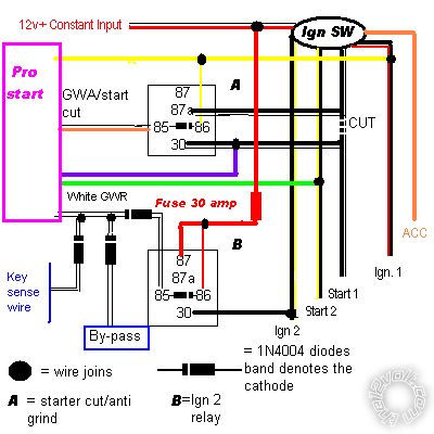
Here's your layout diagram. Program GREEN as second starter:-
camry_layout.bmp------------- Amateurs assume, don't test and have problems; pros test first. I am not a free install service.
Read the installation manual, do a search here or online for your vehicle wiring before posting.
Posted By: howie ll
Date Posted: November 05, 2012 at 7:20 AM
BTW I went to Xpresskit and downloaded the info, very confusing.
But cheaper than a second chipped key no doubt.
-------------
Amateurs assume, don't test and have problems; pros test first. I am not a free install service.
Read the installation manual, do a search here or online for your vehicle wiring before posting.
Posted By: hammerhead786
Date Posted: November 05, 2012 at 8:53 PM
wooohooo wrote:
I'm not a professional... noob and first install or process of. But I found this to be very informative
https://www.bulldogsecurity.com/pdf/ModelsRS82_85.pdf
As for the relay... I think it should be something like this..
https://www.the12volt.com/relays/relaydiagram10.html
Check out the other diagrams they have plenty.
and the 5th relay should attach to your starter with jumper setting.
Thanks very much wooohoo.
Posted By: hammerhead786
Date Posted: November 05, 2012 at 8:54 PM
howie ll wrote:
BTW I went to Xpresskit and downloaded the info, very confusing.
But cheaper than a second chipped key no doubt.
Glad I am not the only one confused. Thanks for all the help, it's much appreciated.
Posted By: swlui
Date Posted: November 06, 2012 at 12:40 AM
I just installed the exact model myself..
So this is what I did for my car (06 corolla), so maybe compare it and you might need some relays or diodes (I didn't need any)
I connected the 2 twelve volt constants together on the remote starter. Then conncet that to the ignition 12volt.
Connected purple wire to starter wire - should onyl show 12 volts when you crank.
Yellow wire goes to one ignition wire (test with multimeter to see), then use the green 5th relay wire and connect to other ignition wire.
Connect orange to acccessories.
This is important is connecting the Black ground wire to a good ground point. you can test this by setting your multimeter in Ohm's setting and check for resistance. If it shows 0 you're golden, anything else no good.
You can forgo the purple tach wire unless your car needs it.
Grey hood switch - find a good point on the hood where you can attach, and attach the wire through the grommet in the firewall. I punched mine through the grommet that did the hood release switch.
Connected orange to my brake wire, near pedal/cylinder. This isn't optional, it turns off the remote starter if the brake is pressed.
Used the yellow parking light. If you connect this one, don't connect the orange parking input on the 12pin accessory.
I don't have a trunk output so I didn't use the Blue wire - you can connect this though.
Connected brown and green to the lock/unlock wire
I didn't need arm and disarm outputs as my car arms/disarms with lock and unlock of the door.
My dome light was a - input so I didn't use the blue/white wire, used the GREY (-) instead to the door trigger wire. This was a tricky tricky position to find. Worst position ever to put a fuse box.
Didn't do starter kill so didn't use WHITE/ orange wire.
Not manual so no parking brake.
Didn't do external trigger input, this is used if you have other systems like alarm or whatever.
No diesel so didn't use glow plug.
Make sure you change the jumper to 2nd ignition or whatever your 5th relay wire is.
Next test your system by putting it into program mode. This is pretty self explanatory. However, if you use the module to program, make sure you put the hood up and the parking light should come on.
After that, prgram your remote. Then after that, put your key into the ignition but in the off position. This should bypass your security. Now try to turn your car on. Make sure your hood is down so your hood pin isnt grounded. If this doesn't work, re-check your connections. Oh yeah, cut that yellow loop if you have an automatic.
If the car starts, then attach your bypass module. I had a PKALL and attached that to the keysense and two other wires. Also I did it D2D. If you do Wire to wire, you will need a few other steps such as cutting off the connector and grounding one wire and other to 12 volt. But this is different for modules. Program module... and voila.
And remember to attach the antenna.
Posted By: howie ll
Date Posted: November 06, 2012 at 3:06 AM
Nice post BUT as per my diagram, TWO starter wires on the Camry, ONE on the Corolla.
-------------
Amateurs assume, don't test and have problems; pros test first. I am not a free install service.
Read the installation manual, do a search here or online for your vehicle wiring before posting.
Posted By: hammerhead786
Date Posted: November 06, 2012 at 6:41 AM
swlui] wrote:
I just installed the exact model myself..
snip
Thank you.
Posted By: swlui
Date Posted: November 06, 2012 at 10:32 AM
Yeah, I should have stated, just a general note so he kind of knows what to do. If you have two starter wires, attach the second starter wire to the 5th relay and move the jumper accordingly instead of where mine went to my 2nd ignition.
Posted By: hammerhead786
Date Posted: November 09, 2012 at 7:20 PM
According to the wiring schematics for the car, the piezo buzzer/chirper for the alarm is connected to the body ecu. As I'd like to connect the horn output from the remote starter to the buzzer, is there anything I need to do to prevent damage to the body ecu?
Thanks in advance,
Hamid
Posted By: howie ll
Date Posted: November 10, 2012 at 2:00 AM
Is that wire a low current (-)NEG trigger?
In other words ground it and that sounds the buzzer?
If that's how it works then you're OK.
-------------
Amateurs assume, don't test and have problems; pros test first. I am not a free install service.
Read the installation manual, do a search here or online for your vehicle wiring before posting.
Posted By: hammerhead786
Date Posted: November 10, 2012 at 5:12 AM
howie ll wrote:
Is that wire a low current (-)NEG trigger?
In other words ground it and that sounds the buzzer?
If that's how it works then you're OK.
It's a programmable 500mA negative output, so it looks like I should be good. Thanks again Howie. I really appreciate all of the time and effort you have taken to help me. 
Posted By: howie ll
Date Posted: November 10, 2012 at 5:40 AM
No the actual vehicle wire. Is this buzzer for the factory alarm or key less entry?
If so test for it with a meter. Don't just hook it up. = Fried ECU or R/S.
TEST TEST TEST TEST
Don't assume.
-------------
Amateurs assume, don't test and have problems; pros test first. I am not a free install service.
Read the installation manual, do a search here or online for your vehicle wiring before posting.
Posted By: hammerhead786
Date Posted: November 10, 2012 at 6:37 AM
My apologies. According to the wiring diagram, it's the keyless buzzer. One side is connected to the ecu and the other goes directly to earth.
Posted By: howie ll
Date Posted: November 10, 2012 at 7:22 AM
Then its POS (+). Unless you have a POS (+) output horn wire or use a relay it won't work.
EARTH? Are you British, Oz or Kiwi?
I thought everyone in North America used "ground".
-------------
Amateurs assume, don't test and have problems; pros test first. I am not a free install service.
Read the installation manual, do a search here or online for your vehicle wiring before posting.
Posted By: hammerhead786
Date Posted: November 10, 2012 at 7:32 AM
Thanks again. LOL...I'm an expat. Next time I'm in the UK, I'll have to buy you a drink.
Posted By: howie ll
Date Posted: November 10, 2012 at 7:36 AM
OK  ------------- Amateurs assume, don't test and have problems; pros test first. I am not a free install service.
Read the installation manual, do a search here or online for your vehicle wiring before posting.
Posted By: hammerhead786
Date Posted: November 10, 2012 at 11:13 AM
howie ll wrote:
Then its POS (+). Unless you have a POS (+) output horn wire or use a relay it won't work.
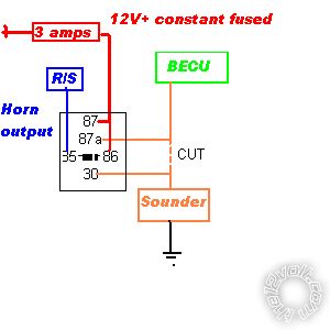
If I decide to use a relay, would I also need to connect a diode to inline to protect the ecu?
Posted By: howie ll
Date Posted: November 10, 2012 at 11:49 AM
This is the safe way using 1 x 1N4004 diode:-
sounder.bmp------------- Amateurs assume, don't test and have problems; pros test first. I am not a free install service.
Read the installation manual, do a search here or online for your vehicle wiring before posting.
Posted By: hammerhead786
Date Posted: November 11, 2012 at 2:02 PM
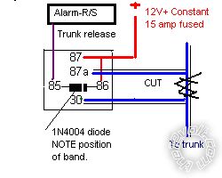
Stupid question of the day. In order to utilise the remote trunk function do I need to user a relay or can I just hook up the trunk release wire from the remote start unit? The car already has remote trunk release.
Posted By: howie ll
Date Posted: November 11, 2012 at 3:58 PM
Use this diagram, the wire you need to cut is a blue/white, DKP test.
trunk_release.bmp------------- Amateurs assume, don't test and have problems; pros test first. I am not a free install service.
Read the installation manual, do a search here or online for your vehicle wiring before posting.
Posted By: hammerhead786
Date Posted: November 12, 2012 at 7:15 AM
howie ll wrote:
Use this diagram, the wire you need to cut is a blue/white, DKP test.
trunk_release.bmp
I really can't say thank you enough Howie. Spent the weekend trying to install the unit, but wasn't having much luck finding all the wires. Finally found all the wires for the remote starter and started prep work to install, only to find I couldn't find the wires for the bypass to connect to! 
More research later and I believe I've figured it out finally. Need to connect the wires from the bypass to the Transponder Key Amplifier and then this thing should be up and running. Now I know what I'm doing next weekend.
Posted By: howie ll
Date Posted: November 12, 2012 at 8:04 AM
As beginner you're doing everything the right way.
-------------
Amateurs assume, don't test and have problems; pros test first. I am not a free install service.
Read the installation manual, do a search here or online for your vehicle wiring before posting.
Posted By: hammerhead786
Date Posted: November 18, 2012 at 8:36 AM
Need some help with the starter kill/anti grind relay as this is confusing me.
On the CT3471-TW
Starter kill output (-) from r/s connects to pin 86 of the relay
Ignition (BLACK/ red) wire connects to pin 85 of the relay
Does the Starter connection from the r/s (purple) wire connect to starter 1 (BLACK/ white) wire at the starter side of the ignition switch?
Relay
Pin 87A - Does the starter 1 (BLACK/ white) cable from the starter side connect here?
Pin 30 - Does the starter 1 (BLACK/ white) cable from the ignition switch side connect here?
Thanks in advance,
Hamid
Posted By: hammerhead786
Date Posted: November 18, 2012 at 9:11 AM
D'oh! Just think I answered my own question.  Found this from the genius that is Howie in another thread...
"Why people are getting flat batteries;
I've seen this posted twice recently and people don't appear to be following the alarm manufacturer's instructions.
An external anti-grind/starter relay should be wired as follows:-
85 Only use the "ground when armed (GWA)" from the alarm.
86 Ignition 1 only.
87a Key side of starter
30 Starter side of cut wire and starter output from R/S.
Diode 1N4004 across 85 and 86 with the band towards 86.
If you join a constant 12V+ to 86 that relay will be on all the time and you will have a flat battery within a day."
I think this answers the above. Now to get stuck in and get this in the car.
Posted By: howie ll
Date Posted: November 18, 2012 at 9:13 AM
Yes but key switch side to 87a and starter side to 30.
If they included a diode looped across 85 and 86, make sure the diode's band (cathode side) goes to the ignition black red.
Actually they have 85 and 86 the wrong way round, it doesn't matter as long as the diode band goes to the ignition side.
Starter connection from remote to 30.
I think I showed that diagram back in your early posts.
-------------
Amateurs assume, don't test and have problems; pros test first. I am not a free install service.
Read the installation manual, do a search here or online for your vehicle wiring before posting.
Posted By: howie ll
Date Posted: November 18, 2012 at 9:15 AM
And here's that diagram again shgows you anti grind and I believe second starter:-
https://www.the12volt.com/installbay/uploads/camry_layout.bmp
-------------
Amateurs assume, don't test and have problems; pros test first. I am not a free install service.
Read the installation manual, do a search here or online for your vehicle wiring before posting.
Posted By: howie ll
Date Posted: November 18, 2012 at 9:19 AM
ShGows?
And the link doesn't work.
try this:- BC1_camry_layout.bmp
Sorry, 2nd. ignition but it shows you everything you need. ------------- Amateurs assume, don't test and have problems; pros test first. I am not a free install service.
Read the installation manual, do a search here or online for your vehicle wiring before posting.
Posted By: hammerhead786
Date Posted: November 18, 2012 at 9:26 AM
Thanks again. I looked at that diagram, over-analysed it, confused myself and gave myself a headache. Apologies yet again. I'll go hang my head in shame.
Posted By: howie ll
Date Posted: November 18, 2012 at 9:31 AM
Come on I have to do this in my head every time I do an install. 
At least I've colour coded it all for you. ------------- Amateurs assume, don't test and have problems; pros test first. I am not a free install service.
Read the installation manual, do a search here or online for your vehicle wiring before posting.
Posted By: hammerhead786
Date Posted: November 18, 2012 at 10:00 AM
Understood. A final couple of questions:
Is an inline fuse required for connecting the relay to the ignition wire or it would it be prudent to have one?
If I connect both 12v connections from the r/s and the fused 12v from the relay for the trunk to the 12 volts at the ignition switch, I take it that it will not cause any issues i.e. trying to run too much from one 12v supply?
Thanks.
Posted By: howie ll
Date Posted: November 18, 2012 at 10:18 AM
1) Definitely not needed you're switching about 1.5 amps.
2) Should be OK but if you have a main fuse box local it would be wise to split those power lines in two and send some to the fusebox supply, thick white.
-------------
Amateurs assume, don't test and have problems; pros test first. I am not a free install service.
Read the installation manual, do a search here or online for your vehicle wiring before posting.
Posted By: afridihamid
Date Posted: November 19, 2012 at 1:01 AM
This may be too late or you may already know this but you can view the specific wiring diagrams for your car from Autostart Canada. This link: https://www.autostart.ca/autosoft/car_select_serial_prostart.aspx
All you have to do is enter the serial number of your prostart unit and select your vehicle.
I'm pointing this out because depending on your vehicle the autostart tech sheet may have pictures of where the wires are located, which can be a big help.
Posted By: hammerhead786
Date Posted: November 20, 2012 at 3:15 PM
afridihamid wrote:
This may be too late or you may already know this but you can view the specific wiring diagrams for your car from Autostart Canada. This link: https://www.autostart.ca/autosoft/car_select_serial_prostart.aspx
All you have to do is enter the serial number of your prostart unit and select your vehicle.
I'm pointing this out because depending on your vehicle the autostart tech sheet may have pictures of where the wires are located, which can be a big help.
Thanks afridihamid. I did download the tech sheet, but I needed to be 100% confident that it was right and that what I would be doing was also right.
Posted By: howie ll
Date Posted: November 20, 2012 at 3:19 PM
Let me assure you both that after nearly 40 years as an installer, diagnostic guru and auto sparks, if I'm working on something new, I'll download every one's crib sheet I can find, cross reference and STILL test and verify before proceeding.
-------------
Amateurs assume, don't test and have problems; pros test first. I am not a free install service.
Read the installation manual, do a search here or online for your vehicle wiring before posting.
Posted By: hammerhead786
Date Posted: November 20, 2012 at 3:51 PM
Installed the unit. In the testing process the car would start, die after about 5 seconds and then try starting itself again. It did this 3 times before giving up. The tach learning wasn't working correctly either. Relocated the tach wire to the ECU and this resolved the issue...success!
Without the planning, reading, questions and testing, I would never have done this right. Without the knowledge and help of Howie II  , I probably would never have even attempted to do this install. In fact, I actually considered giving up at one point.
As Howie's signature says "Amateurs assume, don't test and have problems; pros test first". All I will say is, ignore this at your own peril.
Hamid
Posted By: howie ll
Date Posted: November 20, 2012 at 4:46 PM
It's a pleasure because you asked reasonable intelligent questions and listened, you also said maybe without realising "stop please explain again I'm not sure". Well I don't mind that although I'm an impatient person, but all your questions were good ones.
-------------
Amateurs assume, don't test and have problems; pros test first. I am not a free install service.
Read the installation manual, do a search here or online for your vehicle wiring before posting.
|