08 altima, autostart as 2381tw fm
Printed From: the12volt.comForum Name: Car Security and Convenience
Forum Discription: Car Alarms, Keyless Entries, Remote Starters, Immobilizer Bypasses, Sensors, Door Locks, Window Modules, Heated Mirrors, Heated Seats, etc.
URL: https://www.the12volt.com/installbay/forum_posts.asp?tid=132679
Printed Date: May 16, 2026 at 3:44 PM
Topic: 08 altima, autostart as 2381tw fm
Posted By: unterstrom
Subject: 08 altima, autostart as 2381tw fm
Date Posted: November 15, 2012 at 3:23 PM
Hi there,
I want to install an Autostart AS-2381TW-FM remote start with an ADS-AL(DL)-N15-EN module in my 08 Altima.
I have all the wiring diagrams from autostart.ca and bulldog security. Also found a post with pictures of every wire.
So finding the wires should not be a problem. I do however have a "few" questions about the different options that come with that particular remote.
I numbered all questions to keep some order:
1. does my particular bypass connect in two way mode (D2D) or one way? if D2D works, is it better than direct wiring?
2. i am note sure what to do with the jumper for Starter 2, Ignition 2 & Accessories 2. What is the purpose of that thing?
3. i have the option to choose between high vs low tach threshold. which one to use?
4. what do i do with AUX1, AUX2 & negative ignition output? why do i need a second ignition connection?
5. why do i need two 12V hook ups (just curious)?
6. i read in a post that it's a good idea to isolate all negative outputs with a diode. how do i know what kind (size?) to use?
7. because of the PTS switch, crank (starter?) becomes a brake switch. does that mean it connects to the same wire as the orange brake switch wire (see diagram)?
8. what's the difference between trunk release (+) and trunk pi (-)? which one do i connect to trunk output at remote?
9. what's positive door input?
10. remote has one wire for door lock and unlock each. car has four doors. how does that work?
11. i am not installing an alarm. do i still need to connect the arm & disarm wires?
12. is the bypass module ready to be installed or do i need to hook it up to reader/scanner?
Anything I should watch out for?
I have done a remote start on a 98 Ranger a few years ago. Was way easier. No doors, trunk or bypass. But this Altima is in a different league.
One more thing, is possible/good to install a five second delay relay on the accessories wire to have the a/c or heat kick in after the car has started. I would assume it's easier on the battery in winter. Where I live (Manitoba) we get up to -35C.
Any help will be greatly appreciated.
Replies:
Posted By: kreg357
Date Posted: November 16, 2012 at 5:13 AM
A lot of questions. The newer vehicles are much different and more delicate than previous models. An improperly
installed system can cause major damage to your vehicle. From your questions, it would appear that you have some
serious studying/learning to do before attempting this task.
1. does my particular bypass connect in two way mode (D2D) or one way? if D2D works, is it better than direct wiring?
A: Can't find an install guide for your 2381, but the 2371 guide states One-Way with ADS or Fortin modules. While
it is more work, W2W always works well. Pre-wire the modules on the bench, prior to actual vehicle install.
2. i am note sure what to do with the jumper for Starter 2, Ignition 2 & Accessories 2. What is the purpose of that thing?
A: It is used to configure the 5th ignition relay output. Don't need it. The only ignition outputs used are Starter
and Ignition.
3. i have the option to choose between high vs low tach threshold. which one to use?
A: Use the ADS AL CA supplied Tach output, hardwired, and try the Tach Learn process with the R/S in Norm or Low.
If it doesn't learn / start properly, switch to High and do the Tach Learn process again.
4. what do i do with AUX1, AUX2 & negative ignition output? why do i need a second ignition connection?
The R/S unit is made to be flexible enough to be able to work on many vehicles, some need those signals, other don't.
There will be plenty of unused wires with your install.
5. why do i need two 12V hook ups (just curious)?
A: In some vehicles, the ignition wires ( IGN1, IGN2, ACC1, ACC2, Starter, etc ) need up to 30 Amps current.
6. i read in a post that it's a good idea to isolate all negative outputs with a diode. how do i know what kind (size?) to use?
A: The standard 1N4001 or 1N4004 diode will work. There is a section on diodes with lots of good info on this site.
7. because of the PTS switch, crank (starter?) becomes a brake switch. does that mean it connects to the same wire as the orange
brake switch wire (see diagram)?
A: Always follow the specified install guide for your vehicle.
8. what's the difference between trunk release (+) and trunk pi (-)? which one do i connect to trunk output at remote?
A: Trunk Release is the R/S's output that is used to pop the trunk. Trunk Pin is a R/S input from the vehicle that
monitors the trunk lid ( open or closed ).
9. what's positive door input?
A: Again, the R/S system in made generic to cover most vehicles. Some vehicles have a door pin system that is (+),
while most have a system that is (-).
10. remote has one wire for door lock and unlock each. car has four doors. how does that work?
A: There is a wire in the vehicle that will lock all doors at once. Same for unlock. ( Think passenger door switch.)
11. i am not installing an alarm. do i still need to connect the arm & disarm wires?
A: The R/S Arm and Disarm output wires are used to arm and disarm the vehicles Factory Alarm system.
12. is the bypass module ready to be installed or do i need to hook it up to reader/scanner?
A: Check for a White Label on the ADS AL CA box. It will indicate the firmware / version loaded at the factory. This
can be changed by anyone with the ADS USB cable and authorized dealer access to their WEB site.
The ADS AL CA and R/S unit basically start and control the vehicle the same way a normal PTS would. There should be no need
to delay the ACC circuits any more than their normal sequence.
-------------
Soldering is fun!
Posted By: unterstrom
Date Posted: November 16, 2012 at 12:44 PM
big thank you to kreg357 for the response.
some things I would like to clarify:
regarding question about AUX1, AUX2 & negative ignition output (question 4). Do I need to connect any of those three wires?
to clarify the PTS question (question 7), the R/S install guide says with PTS crank becomes the brake switch. what do I do with the regular brake switch wire?
about question 10: would priority lock work through that one wire?
about question 11: the wiring guide says arm &disarm are "with" lock & unlock respectively. how do I interpret that?
something totally different: what is the significance of the polarities? If the output/input at the R?S is negative, does that mean the receiving wire in the car has to be the opposite or same polarity?
I know that's a lot of questions, but I like to know why things are done a certain way and not just how it's done.
Thanks again
Posted By: kreg357
Date Posted: November 16, 2012 at 2:37 PM
In round two the questions get tougher....  ( Please note that I am not an MECP instructor, or even close.)
regarding question about AUX1, AUX2 & negative ignition output (question 4). Do I need to connect any of those three wires?
AUX1 and AUX2 are not needed for a basic install. They can be used for many things if desired, depending on the R/S's programming
capabilities, the vehicles features / capabilities, etc. Typical uses include window roll-up / roll-down, defroster activation
and even turning on the heated seats or selecting a power seat memory position. The (-) Ignition output is usually used for
controlling an external relay to power an additional Ignition wire, some vehicles have up to three Ignition wires. It can sometimes
be used as a Ground When Running output for a bypass module if your R/S does not already have a output labeled as such ( I have never
used an AutoStart unit and can not find the install guide for your 2381 model ) and you are going in W2W mode.
to clarify the PTS question (question 7), the R/S install guide says with PTS crank becomes the brake switch. what do I do with the regular brake switch wire?
The R/S ?Orange? Brake (+) input wire is connected to the ADS AL CA GREEN/ Red Brake (+) output wire as shown in the install diagram.
A few things to point out here. The ADS bypass module supplies the R/S with the brake pedal signal it derives from the CAN data,
not directly from the brake pedal like normal installs. The remote start "take over procedure" is different from the usual install
( brake pedal pressed ), it is a 45 second time limit from the drivers door opening. The ADS module does not "monitor" the brake
pedal wire status during cranking nor pass that status on ( while the R/S's Starter output is applied to the Brake wire & cranking
the vehicle ) .
about question 10: would priority lock work through that one wire?
No. That wire, if hardwired from the R/S, would unlock all doors. Remember that for your 2008 Altima, the R/S will control the cars
locks thru the ADS bypass module, which controls the locks thru the CAN data connection.
about question 11: the wiring guide says arm &disarm are "with" lock & unlock respectively. how do I interpret that?
The wiring guide supplies general information about the vehicle to aid the installer. This info is not and can not be specific to
the functions of any particular bypass module. The newer vehicles with PTS are very different from typical key start vehicles.
The bypass manufactures provide modules and detailed installation guides with very complete wiring diagrams that actually include
the R/S ( albeit a generic one, that they did not manufacture ). Again, follow the ADS NI5 install guide.
something totally different: what is the significance of the polarities? If the output/input at the R?S is negative, does that mean the receiving wire in the car has to be the opposite or same polarity?
Two things here. The R/S and bypass module have signals marked as Input or Output and (-) or (+) as does the vehicle.
Input signals are ones they receive and monitor for various purposes. The R/S watches the (-) Hood Pin input wire to know when the
hood is open or closed and uses it to allow a remote start or shutdown a remote started engine.
Output signals are created by the R/S or bypass module and wired to the vehicle ( or each other ) to perform a specific function. The
R/S's (-) Horn output is connected to the correct (-) Horn wire in the vehicle to beep the horn at the R/S's direction.
Signal Polarity. For an Input wire, it is expected polarity and or the correct polarity to perform the desired task / function. If
the vehicle needed a (-) signal to flash the Parking Lights and the R/S's (+) Parking Light output wire was ( incorrectly ) connected,
the R/S wouldn't be able to get the vehicles Parking Lights to come on AND might damage the vehicle.
For an output wire, it the the polarity of the active output. In some instances, this output is selectable ( IE the R/S's Parking
Light output can be jumper selectable to either ?(+) or (-) ).
Proper use of the Digital Multi Meter is essential to locate and verify vehicle wires used for the install. ( Except DATA type
wires. Rely on the bypass manufactures install guide and common sense for those.)
-------------
Soldering is fun!
Posted By: unterstrom
Date Posted: November 17, 2012 at 9:28 PM
going back to the tach question, I am supposed to bypass tach output, hardwired. But according to the wiring diagram ADS tach output is connected to R/S tach input, but no mentioning of a wire running to BCM or engine bay.
Same scenario with the hood switch, bypass has a hood status output which connects to R/S input for hood. Where does the actual switch connect to?
When using 1 way mode for the bypass:
- do I need the data cable at all?
- 12V, ground and ground when running are shown as not required, but how is the bypass powered?
What do I do with starter kill output and ground when running?
Is it recommended to wire doors and trunk to R/S and bypass or just R/S(ADS wiring diagram shows it as optional)?
Posted By: kreg357
Date Posted: November 17, 2012 at 11:13 PM
First you must decide if you are going with the one-way D2D mode or going W2W mode. If you choose D2D, then only the
necessary Red wires will be hardwired. The rest ( dashed black ) will be data thru the D2D harness. In either mode
you must hardwire the solid Black lines. In D2D, the ADS bypass module will get its power, ground and GWR signal
thru the D2D harness. In W2W mode you will cut the D2D harness and hardwire the Red - Power, Black - Ground and
Blue/White - GWR wires ( and hardwire all the dashed black, red and solid black wires ).
Tach :
In this installation, assuming one-way D2D, the wire connections indicated on the install diagram in Red must
be hardwired. You only need one Tach source to supply the R/S input, so use the ADS bypass modules' Tach. I
have found it quite reliable with most R/S brands and models.
Hood :
As per this note in the ADS install guide, the Hood Status output will only be available on vehicles that have the
factory installed hood pin ( usually vehicles with factory alarm systems ).
Note 3 Available only when a factory hood switch is present.
If you have it, use the ADS hood pin status output for the R/S's hood pin input. If you don't have it, then install
the hood pin supplied in the R/S kit. It is an important safety feature.
Starter Kill :
Starter Kill is the way the R/S prevents the starter engaging while the R/S is armed/locked. It sometimes can be
also used for Anti-Grind. The anti-grind is already built in to this vehicle. Starter Kill circuits cut into the
vehicles Starter wire and add a relay. Personally, I don't think Starter Kill is worth the liability or exposure for
the "extra security" it provides. Does you car have the Factory Alarm? It already has a fairly sophisticated ignition
immobilizer system.
I am not sure if your R/S 2381 system is an alarm system also. If it is, then it will need the door and trunk status
inputs. Those are supplied by the ADS bypass module and shown as red wires in the install diagram. The E-Brake Status
signal is usually used on R/S installs on vehicles with manual transmissions.
Here is a bench prepped R/S w/keyless unit in W2W mode with an iDatalink bypass module for a Chrysler install :
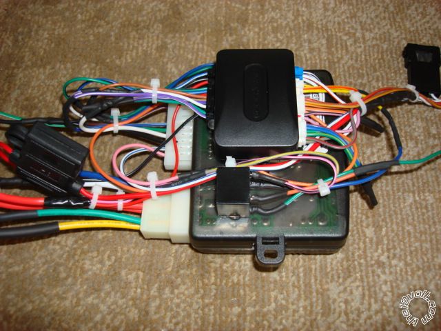
-------------
Soldering is fun!
Posted By: unterstrom
Date Posted: November 18, 2012 at 10:04 PM
I hope these are the last ones:
1. one way D2D versus W2W, which is better for reliability and maintenance free operation?
2. for D2D I don't see a Tach input at the bypass module. Where does the bypass get the signal from?
3. in W2W, do I ignore the Tach output at the bypass module and connect the R/S to the Tach wire?
4. in W2W would the Ground at R/S (wire 1, black) and Ground when running (wire 10, white) connect directly to proper inputs at the bypass module? Would the R/S be grounded through the bypass module ground in this case?
5. is it better to connect the Ground wire to the car frame or an existing Ground wire?
6. in W2W is the 12V at the bypass module spliced into a 12V wire at the R/S?
7. my Altima has Factory Alarm but the R/S 2381 is not an alarm system. Does this mean lock, unlock, door & trunk outputs/inputs at R/S are wired directly into the cars system ignoring the bypass module?
8. R/S doesn't have a dedicated trunk input, but the user guide shows an option to program the External Trigger output for "Zone 3 with disarm/arm (Trunk monitor)". Does that mean the Ext. Trigger output can be used as a trunk input when programmed properly?
9. Trunk output at R/S is (-). Autostart wiring info shows Trunk release (+) (purple, at BCM white 12 pin plug, pin 4). Is the difference in polarities a problem? Do I need a relay to reverse Trunk release to (-)?
10. Coming back to the PTS question: according to R/S install guide Disarm output (wire 5) becomes PTS. But the bypass module has a PTS output as well. Does that make the Disarm output at R/S a Disarm again?
Something I am struggling to wrap my brain around is the wiring diagram for the bypass module. It shows all these outputs and inputs such as unlock, lock, trunk status, etc. from bypass to R/S. But where is all this connected to the actual components (doors, trunk, door pin etc.)?
Posted By: kreg357
Date Posted: November 18, 2012 at 11:36 PM
Round 4 of the $64,000 pyramid... 
1. one way D2D versus W2W, which is better for reliability and maintenance free operation?
A: IMHO, W2W is the best way to go. Making all the R/S to bypass connection on the bench with solder joints and
heat shrink tube provides the best reliability.
2. for D2D I don't see a Tach input at the bypass module. Where does the bypass get the signal from?
A: In this case the ADS bypass module obtains the tach info from the CAN data and outputs it in standard form to
the R/S. It does the same for Door Status, Trunk Status, Brake, EBrake, etc.
3. in W2W, do I ignore the Tach output at the bypass module and connect the R/S to the Tach wire?
A: Typically you use the Tach signal supplied by the ADS module. It is preferable to making a direct Tach
connection to the vehicle if you must run a wire thru the firewall and into the engine compartment. Of course
you can always go directly to the vehicle for Tach ( and other signals ) if you wish.
4. in W2W would the Ground at R/S (wire 1, black) and Ground when running (wire 10, white) connect directly to proper
inputs at the bypass module? Would the R/S be grounded through the bypass module ground in this case?
A: The bypass module sometimes has connections to the same vehicle wires that the R/S does. They both need to see those
same signals. If you look closely at the R/S + bypass picture, you will see where a few of the bypass module's
wires are tapped in to the R/S's wires ( like Ground, +12V constant, Ignition, etc ) which continue on to the vehicle
wire connection point. In your application with W2W, you would do this to bypass Ground, +12V power and Ignition.
5. is it better to connect the Ground wire to the car frame or an existing Ground wire?
A: I like to find a very solid frame bolt to connect the R/S ground wire to. I always solder on a terminal ring to the
R/S ground wire. At times this chassis frame bolt is already being used as a vehicle ground point with other wires
attached. I have not have any problems with this type of ground connection.
6. in W2W is the 12V at the bypass module spliced into a 12V wire at the R/S?
A: Yes, notice the photo and the thick Red wire with two additional thin wires ( Red and Pink ) spliced into it,
after the fuse. Thin Red goes to the bypass and thin Pink goes to a external relay.
7. my Altima has Factory Alarm but the R/S 2381 is not an alarm system. Does this mean lock, unlock, door & trunk
outputs/inputs at R/S are wired directly into the cars system ignoring the bypass module?
A: No. Follow the ADS install diagram and notes.
8. R/S doesn't have a dedicated trunk input, but the user guide shows an option to program the External Trigger output for
"Zone 3 with disarm/arm (Trunk monitor)". Does that mean the Ext. Trigger output can be used as a trunk input when
programmed properly?
A: Can't answer this one. Not familiar with the AutoStart units and don't have an install guide for this model.
9. Trunk output at R/S is (-). Autostart wiring info shows Trunk release (+) (purple, at BCM white 12 pin plug, pin 4). Is the
difference in polarities a problem? Do I need a relay to reverse Trunk release to (-)?
A: It would be a minor issue if you were going to have the R/S directly pop the trunk. In that case you would need a relay
to change the signals polarity. However, if you look at the bypass modules listed capabilities and wiring diagram, you
will see that the R/S's (-) trunk release output is exactly what the bypass module is looking for. The bypass
module takes this input and places a "trunk release command" on the CAN bus for the vehicle to execute.
10. Coming back to the PTS question: according to R/S install guide Disarm output (wire 5) becomes PTS. But the bypass module
has a PTS output as well. Does that make the Disarm output at R/S a Disarm again?
A: Don't understand this question. The guide you should be going by is the ADS AL(DL) NI5 Type 1 diagram. Hopefully
the R/S unit you have chosen has all the necessary outputs that the bypass module needs ( IGN1, Starter1 & Starter2 ).
Something I am struggling to wrap my brain around is the wiring diagram for the bypass module. It shows all these outputs and
inputs such as unlock, lock, trunk status, etc. from bypass to R/S. But where is all this connected to the actual components
(doors, trunk, door pin etc.)?
A: All of that info is bundled together and placed on the vehicles CAN bus data wires. The ADS bypass module taps into this data.
Think of the CAN bus as a two way multiplex super highway. The bypass module speaks this language and taps into the data
flow, reading / collecting info passively ( tach, door status, etc ) and also inputs its' own commands at times ( unlock,
engine start, disarm, etc ).
-------------
Soldering is fun!
Posted By: afridihamid
Date Posted: November 19, 2012 at 12:05 AM
1. Wire to wire should be very reliable if connections are soldered properly. Kreg could chime in on D2D reliability (I've had little experience w/ D2D).
2. The bypass receives the tach signal through the CAN data port from the vehicle. In 1way D2D mode or W2W mode, the tach output wire should be connected to the tach input wire of the R/S.
3. In W2W you should connect the tach output wire from the bypass to the tach input of the R/S. It will save the time and trouble as opposed to running the R/S tach directly to a tach source in the vehicle.
4. The white GWR output wire from your R/S connects to the Blue/White GWR input of the bypass. The R/S sends a ground through this wire to tell the bypass to kick in during a remote start run; It kills the ground after the remote start shuts off, effectively telling the bypass to stop bypassing.
You can tie the ground wires from the bypass and R/S together and then have them ground to a bolt on the chassis (the R/S will not ground through the bypass and they must go to a bolt using a ring terminal).
5. Better to use a ring terminal and find a factory bolt or use your own, don't use a factory ground wire.
6. You may connect to the 12volt of the R/S or any 12volt constant wire (much easier to connect at the R/S 12v).
7. No, connect the lock/unlock, door pins, etc. to the bypass. It's there as a convenience so you don't have to run these wires in the vehicle. The bypass will take care of the communication through the CAN bus.
You may need to connect the arm/disarm wires directly to the vehicle's wires (read the note on your bypass diagram regarding arm/disarm).
8. I'm not sure why you would connect the trunk pin when your R/S unit doesn't have an alarm. Unless your 2way unit displays trunk pin activity, I don't see the need for hooking it up.
9. Always confirm the wire and test polarity with a DMM. That being said, if you were to connect the R/S trunk release (-) output directly to vehicle, it would need a relay to convert the polarity of the trunk wire to (-).
In your case all you need to do is connect the (-) trunk release output wire from the R/S to the (-) trunk release input of the bypass and it will take care of it (no relays needed).
10. Someone else will have to answer the question regarding the PTS...
Think of it this way, an input is something the unit has to receive/monitor and output is something it has to send out.
Ex: A tach output is a tach signal sent out (be it from the vehicle tach wire or the bypass tach output). A tach input is the signal an R/S unit receives/monitors...
Also note: I see the install guide for the bypass shown in the first pic is for Type 1 install. However, when I looked at the Install Type Selection on page 2 of the pdf, your 08 Altima falls under Type 2 install... Make sure you confirm and use the right one.
Posted By: afridihamid
Date Posted: November 19, 2012 at 12:14 AM
Posted By: kreg357
Date Posted: November 19, 2012 at 6:07 AM
At least a half hour, I'm a slow typist. I'm still soaking my fingers in Epsom salts right now. 
Thanks for the assist and confirmations! One thing I might be confused on and should be cleared up by the OP.
Is this Altima an Auto Trans or Manual Trans vehicle? I missed it if you already mentioned it.
It is important because it determines which ADS AL(DL) NI5 install Type you follow. Type 1 = Auto, Type 2 = Manual.
-------------
Soldering is fun!
Posted By: unterstrom
Date Posted: November 19, 2012 at 6:47 PM
Was very helpful.
Called Autostart about the PTS question and got that clarified.
Have to call them one more time though about positive Ext. Trigger being programmed to act as negative Trunk input and loosing Key sense in the process. Apparently I have to choose between those two.
Otherwise I think I am ready to get started.
By the way, I can see somebody post a question shortly before midnight. But answering a question around/after midnight...
That's some dedication. Hats off to you.
Posted By: unterstrom
Date Posted: November 21, 2012 at 12:33 PM
So I got started last night. Hooked up a couple wires, lost some bolts. Going ok I guess. However I can't find the arm and disarm wires in the drivers side harness. What's the procedure (using a DMM) to check for them?
One complaint to nobody in particular: why are the wires at the R/S so much heavier compared to the ones in the car? Not fun trying to solder them in an ackward position.
Posted By: kreg357
Date Posted: November 21, 2012 at 3:28 PM
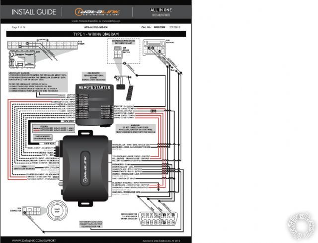
Guess I'm confused. According to the ADS AL(DL) NI5 Type 1 install instructions / diagram, the optional Arm and
Disarm connections are made at the BCM. The BCM is conveniently hidden behind the instrument cluster. 
However, here is a note from Page 9 of the install guide :
ARM/DISARM WARNING:
1-THE MODULE DOES NOT CONTROL THE OEM ALARM ARM BY DATA.
2-THE MODULE DOES CONTROL THE OEM ALARM DISARM BY DATA.
(IGNITION WILL TURN ON AND OFF ONCE)
TO VOID THE OEM ALARM CONTROL BY DATA:
1-CONNECT ARM/LOCK FROM THE RS TO THE BCM
2-CONNECT DISARM/UNLOCK FROM THE RS TO THE BCM
3-CONNECT MODULE PURPLE / YELLOW WIRE TO GROUND
What this means :
The ADS AL CA bypass module flashed with ADS AL(DL) NI5 firmware will disarm the Factory alarm system with an
Ignition and transponder bypass pulse ( with an Unlock command from the R/S ). It won't arm the Factory alarm
system thru CAN data. You would control the arming of the Factory alarm by pressing the Lock button on the
door as you exit the vehicle ( or use the Factory FOB Lock button ). This is the standard install method and
requires no connections to the BCM ( top paragraph above and standard wiring shown in Type 1 diagram ).
If you want to control the Factory alarm system differently, you must make the necessary connections noted in the
second paragraph above ( and shown as optional on the Type 1 install diagram ). This method bypasses the ADS module
and disables it from controlling the locks and Disarm thru CAN data. The R/S would directly interface the vehicle
for Lock/Arm and Unlock/Disarm.
As for the thick R/S ignition wires, remember the aftermarket R/S system are made to work on wide variety of
vehicles. While some newer vehicles have thin ignition wires older vehicles do not and can draw 30 Amps.
-------------
Soldering is fun!
Posted By: unterstrom
Date Posted: November 21, 2012 at 10:34 PM
Would be great.
Posted By: unterstrom
Date Posted: November 23, 2012 at 12:34 PM
I took out the main door switch. Found two sets of blue-red and blue-black wires. One set is thin gauge, the other is heavier gauge. How can I determine which set is rearm/disarm?
Posted By: unterstrom
Date Posted: November 23, 2012 at 12:42 PM
Another question: I read somewhere that it's possible to connect power windows up/down to power lock/unlock. And when you press and hold the unlock button on the remote the windows would be lowered. Same for holding lock and raising the window. I guess the remote continues emitting a pulse as long as the button is depressed.
Is that true?
Posted By: KPierson
Date Posted: November 23, 2012 at 8:44 PM
-------------
Kevin Pierson
Posted By: unterstrom
Date Posted: November 24, 2012 at 9:10 PM
Does anybody know why I can't get my autostart as-2381 to enter programming mode. I think it did the very first time, but I ran out off time. After that, nothing. I made sure the R/S wasn't in valet mode, still no luck.
Posted By: unterstrom
Date Posted: November 24, 2012 at 10:16 PM
Posted By: kreg357
Date Posted: November 25, 2012 at 4:55 AM
Sorry, can't help with programming your AutoStart system, not one of my usual brands.
The "How to Identify Vehicle Year" info/chart on Page 15 of the install guide is in all the install
guides. They ( iDatalink ) just include as a referrence to make things easier for the installer.
As long as you followed the Type 1 install and the wires matched up with the '07-'08 Altima chart,
you should be good to go.
-------------
Soldering is fun!
Posted By: unterstrom
Date Posted: November 26, 2012 at 5:43 PM
-------------
"Good judgment comes from experience. Experience comes from poor judgment."
-unknown
Posted By: unterstrom
Date Posted: November 26, 2012 at 6:21 PM
-------------
"Good judgment comes from experience. Experience comes from poor judgment."
-unknown
Posted By: unterstrom
Date Posted: December 14, 2012 at 3:21 PM
I can't remote start my 08 Altima PTS. Decided to check all wires with a DMM during remote start. All wires show activity/voltage spike during a remote start except for Brake Status (2V DC steady) and ignition output (0v).What could be the problem?
Hardware: Autostart as-2381 & ADS AL CA
w2w, VTS, bypass is flashed for latest firmware
-------------
"Good judgment comes from experience. Experience comes from poor judgment."
-unknown
Posted By: unterstrom
Date Posted: December 16, 2012 at 10:19 PM
Also, what is the correct procedure to program the bypass?
Heard different opinions on that. Some say to use the fob but without the key and battery. Others say to connect GWR and brake status after programming.
I tried all of that as well as using the fob with key and battery.
Didn't make a difference. What is the correct for an ads bypass?
Thanks
-------------
"Good judgment comes from experience. Experience comes from poor judgment."
-unknown