Where to Connect Ignition from RS Unit? 2003 Nissan Pathfinder
Printed From: the12volt.com
Forum Name: Car Security and Convenience
Forum Discription: Car Alarms, Keyless Entries, Remote Starters, Immobilizer Bypasses, Sensors, Door Locks, Window Modules, Heated Mirrors, Heated Seats, etc.
URL: https://www.the12volt.com/installbay/forum_posts.asp?tid=132702
Printed Date: May 16, 2026 at 12:14 AM
Topic: Where to Connect Ignition from RS Unit? 2003 Nissan Pathfinder
Posted By: afridihamid
Subject: Where to Connect Ignition from RS Unit? 2003 Nissan Pathfinder
Date Posted: November 18, 2012 at 2:42 AM
I'm installing remote start on a 2003 Nissan Pathfinder. I'll be using the idatalink ADS-TB unit to bypass the immobilizer..
According to the bypass diagram, I believe the 8pin harness shown is coming from the ignition switch (right?).
It will require me to cut the ignition wire from the vehicle and connect the ends to two wires from the bypass unit.
My main question, if this is the case which side of the cut ignition wire do I connect the ignition signal from the RS unit??? And does it make a difference?
Never worked with this car or bypass module so I'm a little confused on that bit, thanks in advance guys.
Replies:
Posted By: lurch228
Date Posted: November 18, 2012 at 3:11 AM
Yes and vehicle side.
And always solder the bypass connections!
Remote Start
WIRE COLOR POLARITY LOCATION
Battery WHITE/ GREEN (+) IGNITION SWITCH HARNESS
Ignition 1 BLACK/ WHITE (+) IGNITION SWITCH HARNESS
Ignition 2 RED / YELLOW (+) IGNITION SWITCH HARNESS
Accessory 1 RED / YELLOW (+) IGNITION SWITCH HARNESS
Accessory 2 WHITE/ YELLOW
Starter 1 BLACK / YELLOW (+) IGNITION SWITCH HARNESS
Starter 2 RED / BLACK (+) IGNITION SWITCH HARNESS
Anti-Theft Type TRANSPONDER
Anti-Theft Descript AN RF SIGNAL ACTIVATED SYSTEM
Key Sense WHITE/ RED (+) IGNITION SWITCH HARNESS
Neutral Safety BLACK (-) AT GEAR SELECTOR SWITCH
Tachometer WHITE/ GREEN (AC) AT MODULE ABOVE GAS PEDAL
ALSO LOCATED AT THE ECM PIN 25
Speed Sense WHITE/ BLUE (AC) AT CRUISE CONTROL MOD IN DRIVER'S KICK PANEL
Parking Lights (RED / BLACK OR PINK/BLACK) (+) DRIVERS KICK OR SILL HARNESS
Low Crr. Pk Lights GREEN (-) SECU MODULE PIN 20 OR AT SWITCH
Brake Lights GREEN/ YELLOW (+) AT SWITCH ABOVE BRAKE PEDAL
Reverse Lights YELLOW (+) IN HARNESS IN PASSENGER KICKPANEL
Horn LIGHT GREEN/ BLACK (-) STEERING COLUMN OR SECU MODULE PIN 42
DIRECTWIRE WIRING INFORMATION - NISSAN / PATHFINDER / 2003 / Remote Start
[PRINT THIS PAGE]
12volts WHITE/ green (40A) + ignition switch
Starter BLACK / YELLOW + ignition switch
Second Starter RED / black + ignition switch
Ignition BLACK/ white + ignition switch
Second Ignition N/A
Third Ignition N/A
Accessory RED / yellow + ignition switch
Second Accessory WHITE/ blue + ignition switch
Keysense RED / blue to WHITE/ red (required) + ignition key switch or SECU, gray 24 pin plug, pin 1
Notes: The SECU (Smart Entrance Control Unit) is to the right of the dash fuse box.
Power Lock use factory alarm arm
Power Unlock use factory alarm disarm
Lock Motor blue 5 wire SECU, gray 16 pin plug, pin 6
Notes: The SECU (Smart Entrance Control Unit) is to the right of the dash fuse box.
Unlock Motor WHITE/ purple 5 wire SECU, gray 16 pin plug, pin 7
Notes: The SECU (Smart Entrance Control Unit) is to the right of the dash fuse box.
Parking Lights+ pink/black + driver kick, harness to rear
Parking Lights- green - SECU, white 24 pin plug, pin 20
Notes: The SECU (Smart Entrance Control Unit) is to the right of the dash fuse box.
Hazards same as turn signals
Turn Signal(L) gray/blue + SECU, gray 24 pin plug, pin 23
Notes: The SECU (Smart Entrance Control Unit) is to the right of the dash fuse box.
Turn Signal(R) gray/red + SECU, gray 24 pin plug, pin 24
Notes: The SECU (Smart Entrance Control Unit) is to the right of the dash fuse box.
Reverse Light yellow + driver kick, harness to rear
Door Trigger RED / blue (all doors), GREEN/ orange (driver door) - SECU, white 24 pin plug, pins 3 and 1
Notes: The SECU (Smart Entrance Control Unit) is to the right of the dash fuse box.
Dome Supervision RED / black - SECU, gray 24 pin plug, pin 7
Notes: The SECU (Smart Entrance Control Unit) is to the right of the dash fuse box.
Trunk/Hatch Pin see left front door trigger
Hood Pin yellow/black - SECU, white 24 pin plug, pin 6
Notes: The SECU (Smart Entrance Control Unit) is to the right of the dash fuse box.
Trunk/Hatch Release WHITE/ green (glass hatch) -high curr driver kick, harness to rear
Power Sliding Door N/A
Factory Alarm Arm yellow (hatch key lock) - SECU, white 24 pin plug, pin 11
Notes: The SECU (Smart Entrance Control Unit) is to the right of the dash fuse box.
Factory Alarm Disarm lt. green (hatch key unlock) double - SECU, white 24 pin plug, pin 10
Notes: The SECU (Smart Entrance Control Unit) is to the right of the dash fuse box.
Disarm No Unlock see factory alarm disarm
Tachometer WHITE/ green ac ECM to right of steering column, pin 103
Wait to start N/A
Brake Wire GREEN/ YELLOW + brake switch, black 2 pin plug or white 4 pin plug, pin 2
Parking Brake BROWN / white or blue/green - parking brake switch or driver kick, harness to rear
Horn Trigger yellow to lt. GREEN/ black - horn switch or SECU, gray 24 pin plug, pin 18
Notes: The SECU (Smart Entrance Control Unit) is to the right of the dash fuse box.
Memory Seat 1 blue / YELLOW - driver kick, brown 16 pin plug, pin 8
Memory Seat 2 green - driver kick, gray 12 pin plug, pin 5
Memory Seat 3 N/A -
Interface Module: Category:
Immobilizer Bypass Required:
Yes Type:
Transponder
Posted By: afridihamid
Date Posted: November 18, 2012 at 4:13 AM
Thanks for the quick reply.
I imagine during a normal engine start with the key the bypass unit will simply complete the connection on the ignition wire that was cut right?
I haven't seen the actual wires but I imagine the ignition wires on the car will be a heavy gauge wire, I'm wondering how the 22 gauge wire from the bypass unit will support the current?
Posted By: lurch228
Date Posted: November 18, 2012 at 4:54 AM
The bypass will hook to the small guage wires to act as the key and key cylinder to the computer. The wires are small guage as the computer is turning relays on and off instead of a switch with heavy gauge wires running all the way to the switch. The bypass identifies wires by plug pin location and the remote start identification is wire color.
Posted By: jstruckman
Date Posted: November 18, 2012 at 10:39 AM
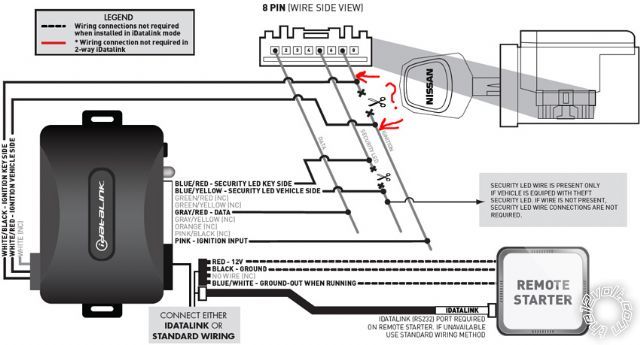
The idatalink diagram shows the wires and connections made at the transponder plug for the bypass. The remote start connections such as ignition, starter and accessory wires will be at a different plug at the ignition harness.
-------------
Posted By: soundnsecurity
Date Posted: November 18, 2012 at 11:23 AM
they are not telling you to connect these wires at the ignition harness, those wires are to be connected probably at the bcm or the imobilizer plug close to the ignition harness. pathfinders are not made with small gauge wires at the ignition harness. do not interrupt the main ignition wire with the small gauge wires from the bypass! no wires other than the main starter(starter kill) should be cut at the main ignition harness
the diagram they give you of that 8 pin plug is exactly what it should look like and should be the same shape. the plug for the ignition harness will be more square.
-------------
Posted By: afridihamid
Date Posted: November 18, 2012 at 4:38 PM
That makes way more sense. I hadn't actually started yet but was confused by the bypass diagram.
As stupid as the question may have been, I had to ask. Thanks for the help guys.
Posted By: soundnsecurity
Date Posted: November 19, 2012 at 11:45 AM
oh and this should help you out to know that you can probably find all of the main ignition wires in the drivers kick panel, the colors might be different but they will be the only heavy gauge wires in the kick panel so just test and verify. i know on my frontier that every wire was there except the 2nd starter, its still much easier than trying to connect at the ignition cylinder.
-------------
|