viper 5704 on 2003 cavalier
Printed From: the12volt.com
Forum Name: Car Security and Convenience
Forum Discription: Car Alarms, Keyless Entries, Remote Starters, Immobilizer Bypasses, Sensors, Door Locks, Window Modules, Heated Mirrors, Heated Seats, etc.
URL: https://www.the12volt.com/installbay/forum_posts.asp?tid=132880
Printed Date: May 06, 2026 at 3:16 PM
Topic: viper 5704 on 2003 cavalier
Posted By: mdaul87
Subject: viper 5704 on 2003 cavalier
Date Posted: December 04, 2012 at 9:40 AM
have just a few questions for the remote start wiring. there are 9 wires as follows:
1. (+) ignition 1 input/output
2. (+) fused (30a) ignition 2/flex relay input 87
3. (+) accessory output
4. (+) starter output (car side)
5. (+) starter output (key side)
6. (+) fused (30a) ignition 1 input
7. (+) ignition 2/flex relay output
8. (+) flex relay input 87a key side (if required) of flex relay
9. (+) fused (30a) accessory/starter input
so heres how i would wire it:
1. connect to the ignition wire in the ignition harness (pink)
2. i dont believe my car has an ignition 2 wire (correct me if im wrong) not used
3. connect to the accessory wire in the ignition harness (orange)
4. cut starter wire (yellow) in ignition harness and connect to the side that runs to the starter
5. connect to the other side of the starter wire that runs to the key
6. ?? detailed instructions describe this wire as: this wire is the polarity feed for the ignition 1 relay. what do i hook this up to?
7. not used
8. not used
9. ?? described as: this wire is the polarity feed to the accessory and starter relays. what do i hook this up to?
any help would be appreciated.
thanks!
Replies:
Posted By: shortcircuit161
Date Posted: December 04, 2012 at 9:56 AM
1. (+) ignition 1 input/output - you are correct
2. (+) fused (30a) ignition 2/flex relay input 87 - to red 12v constant
3. (+) accessory output - you are correct
4. (+) starter output (car side) - you are correct
5. (+) starter output (key side) - you are correct
6. (+) fused (30a) ignition 1 input - to red 12v constant
7. (+) ignition 2/flex relay output - to brown 2nd ACC wire - change option in Viper for 2nd ACC
8. (+) flex relay input 87a key side (if required) of flex relay - you are correct
9. (+) fused (30a) accessory/starter input - to red 12v constant
Also make sure you have a bypass module for the Passlock II on that car for the remote starter.
-------------
Posted By: mdaul87
Date Posted: December 04, 2012 at 10:18 AM
thanks for the help!
i have purchased the xpresskit pljx for the passlock bypass. but now looking at the wiring for that i've confused myself again... their diagram is a little strange
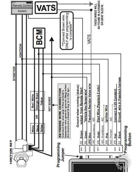
im not sure what the brown wire (ground when running status output from remote start) connects to on the 5704.
also im assuming to just ignore the vats part of the diagram
the last thing is the keysense wire. i dont think my car has that wire. only 3 wires are there (white, black and yellow). safe to just ignore this wire as well?
Posted By: shortcircuit161
Date Posted: December 04, 2012 at 10:45 AM
The brown (GWR) wire from the PLJX goes to the Dark Blue status output wire from the Viper. That's what tells the module that remote start is about to run.
You are correct, you wouldn't use the VATS section. That's a different and older type of antitheft system.
Keysense isn't necessary for this setup.
The white, black and yellow are the Passlock II wires that you will connect the PLJX to. Make sure the jumpers are set correctly before programming it.
-------------
Posted By: mdaul87
Date Posted: December 04, 2012 at 10:53 AM
feel kinda dumb about the dark blue wire on the 5704. i was scanning the manual for the word ground, not status but i see it now. i was only finding the ground when armed output wire.
now if the ups man would just hurry up and get here... lol ill post back to let you know how it goes.
thanks again for the help!
Posted By: mdaul87
Date Posted: December 04, 2012 at 11:42 AM
sorry one more question...
i have the car taken apart and have access to the ignition harness, problem is there are two red wires, one brown and then the yellow, pink and orange. both red test at 12v when the car is off with no key in the ignition. does it matter which one i use?

Posted By: shortcircuit161
Date Posted: December 04, 2012 at 12:04 PM
Either red is fine to use. They both supply more than enough power (50A) for the remote starter.
If one red is noticeably thicker than the other, use the thicker one.
Otherwise, either should work fine.
-------------
Posted By: howie ll
Date Posted: December 04, 2012 at 12:32 PM
Or both, supply half of your 12V constants to each.
-------------
Amateurs assume, don't test and have problems; pros test first. I am not a free install service.
Read the installation manual, do a search here or online for your vehicle wiring before posting.
Posted By: soundnsecurity
Date Posted: December 04, 2012 at 2:03 PM
i always use both to avoid problems that can happen when you draw too much current through a single wire. that is also why there are two wires to begin with. it doesnt matter which red wires from the alarm you hook to which wire on the car.
-------------
Posted By: mdaul87
Date Posted: December 06, 2012 at 5:00 PM
i used both red wires. it was a little weird getting in the menu to program the transmission mode, listening to/counting siren chirps etc but i figured it out
so the remote start, door locks, alarm and trunk release all work great... as far as the parking light flashes im not sure how to hook that up.
i have 2 wires:
1. parking light isolation wire (pin 87a of onboard relay) (WHITE/ brown)
2. parking light output (white)
i'd also like to try to get the rear defrost to turn on when remote started but im not sure the difference between latch and pulse rear defogger
Posted By: offroadzj
Date Posted: December 06, 2012 at 5:21 PM
Parking lights: You want the White output. The isolation wire is only used when you need to isolate the parking light output from the switch.
Defogger: You need to test the rear defogger activation in the car. If the wire shows momentary ground only with the button pressed then it is pulsed. If you press and release the switch and the ground stays active then it is latched.
-------------
Kenny
Owner / Technician
KKD Garage LLC
Albany, NY 12205
Posted By: howie ll
Date Posted: December 06, 2012 at 5:24 PM
Damn Kenny, you beat me again, it's a brown POS (+) on a blue plug at the BCM so as Kenny says disregard the WHITE/ brown, only use the white and make it's output POS (+) via the internal fuse.
Pulse = momentary.
Latched = switched constantly.
-------------
Amateurs assume, don't test and have problems; pros test first. I am not a free install service.
Read the installation manual, do a search here or online for your vehicle wiring before posting.
Posted By: smokeman1
Date Posted: December 06, 2012 at 8:20 PM
You basically you have to get behind where the switch is located and meter the wires going to it. It should read:
12 volts then when you press the button it drops to 0 Volts then jumps back to 12 volts. This is called a (-) pulsed defroster.
12 volts then when you press the button and drops to 0 volts and stays there. This is (-) latching defroster.
0 volts then when you press the button it jumps to 12 volts. This is a (+) latched defrost and may requires a relay to switch polarity. ------------- When all else fails, Read the Instructions
Support the12volt.com Make a Donation
Posted By: mdaul87
Date Posted: December 06, 2012 at 8:25 PM
howie ll wrote:
Damn Kenny, you beat me again, it's a brown POS (+) on a blue plug at the BCM so as Kenny says disregard the WHITE/ brown, only use the white and make it's output POS (+) via the internal fuse.
Pulse = momentary.
Latched = switched constantly.
ok i found the brown wire at bcm. how do i change that fuse? right now it seems as its not plugged in to anything. i have 3 female slots on the left in a vertical line and the fuse sitting vertically to the right of that line. the only thing i see in the installation manual involves replacing the fuse with a resistor and using both the white and the WHITE/ brown isolation wire.
by the way i am using the 5901 install guide as a reference. i could not find one for the 5704 anywhere. only found the quick reference for the 5704. does anyone have access to a complete install guide for the 5704?
Posted By: mdaul87
Date Posted: December 06, 2012 at 9:04 PM
mdaul87 wrote:
how do i change that fuse? right now it seems as its not plugged in to anything. i have 3 female slots on the left in a vertical line and the fuse sitting vertically to the right of that line. the only thing i see in the installation manual involves replacing the fuse with a resistor and using both the white and the WHITE/ brown isolation wire.
and nevermind, sorry. i looked at the 5704 quick reference again and its shown in the diagram..
Posted By: mdaul87
Date Posted: December 07, 2012 at 6:40 PM
any ideas on how i can remote start but have the stereo stay off until i actually get in the car?
i have a pioneer x6500bt. it trys to auto pair with my iphone via bluetooth when it turns on but when i remote start i am not in bluetooth range of my car. so when i actually get into my car, i have to manually pair my phone.
i know this seems like a minor annoyance but anyone have any ideas?
Posted By: howie ll
Date Posted: December 08, 2012 at 2:27 AM
To be honest, no.
I have a "link to cell" at home which reaches to where my car is parked.
I have exactly the same problem of R/Sing the car, of getting 100 yards down the road and wondering why my BT display doesn't say "HOWARD".
-------------
Amateurs assume, don't test and have problems; pros test first. I am not a free install service.
Read the installation manual, do a search here or online for your vehicle wiring before posting.
Posted By: soundnsecurity
Date Posted: December 08, 2012 at 9:38 AM
use a relay to break the red wire from the radio during remote start will keep the radio off until you deactivate the remote start.
85: ground when running
86: ignition
87a & 30: split the red wire at the radio between the two pins.
-------------
Posted By: mdaul87
Date Posted: December 08, 2012 at 10:07 AM
i have a 2003 cavalier, pioneer x6500bt and a viper 5704.
i want to have the stereo only get power when the car alarm is disarmed and running. reason being, when i remote start my car, the stereo turns on and attempts to pair via bluetooth to my iphone, but i am never in bluetooth range when i remote start the car so i have to manually pair my phone every time now.
the 5704 has a -500mA ground when armed wire and i am hoping to use this with a relay. heres what ive come up with:
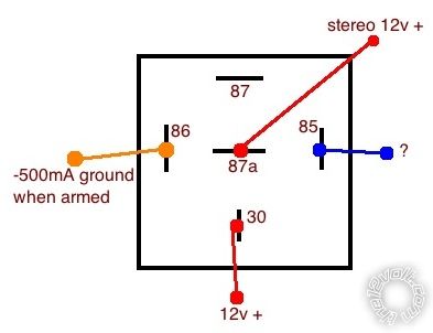
im not sure what to energize the coil with though. im worried about the voltage spike if i use a 12v+ on the 85 pin. any help would be appreciated
Posted By: mdaul87
Date Posted: December 08, 2012 at 10:19 AM
soundnsecurity wrote:
use a relay to break the red wire from the radio during remote start will keep the radio off until you deactivate the remote start.
85: ground when running
86: ignition
87a & 30: split the red wire at the radio between the two pins.
didnt think about splitting the wire at the stereo, that makes a lot more sense than what i came up with. as far as 85 and 86, is there a way i can use that ground when armed wire instead? id prefer it to work off of that instead of whether the remote start is active.
Posted By: soundnsecurity
Date Posted: December 08, 2012 at 11:24 AM
you could but what if you remote start the car when the alarm is disarmed? using the ground when running is the most fool proof way to fix your problem. the radio will turn on when you take over the car which definitely puts you in range of the pioneer.
-------------
Posted By: howie ll
Date Posted: December 08, 2012 at 11:32 AM
Correct wiring after the above posts.
GWR to 85 via a 1N4004 diode.
Ignition to 86.
ACC from switch to radio 87a
To radio 30.
Second 1N4004 across 85 and 86, band side to 86.
Both diodes are mandatory.
If the above doesn't work, 12V+ constant to 86 via a 2 amp fuse.
-------------
Amateurs assume, don't test and have problems; pros test first. I am not a free install service.
Read the installation manual, do a search here or online for your vehicle wiring before posting.
Posted By: mdaul87
Date Posted: December 08, 2012 at 12:16 PM
soundnsecurity wrote:
you could but what if you remote start the car when the alarm is disarmed? using the ground when running is the most fool proof way to fix your problem. the radio will turn on when you take over the car which definitely puts you in range of the pioneer.
this is true, but i would never remote start the car with the alarm disarmed. its always either parked on the street near my house or in the parking lot at work.
where does the gwr wire come from?
Posted By: soundnsecurity
Date Posted: December 08, 2012 at 12:19 PM
well the other downside of using the ground when armed is that the relay would be active the whole time your alarm is armed. i like to keep relays off whenever possible because they do draw some current and if you leave it sitting long enough it will kill your battery.
my way the relay will only be on during remote start when the car is running.
the GWR comes from the remote starter, on a viper alarm its called the status output. your bypass should also be hooked to this wire
-------------
Posted By: mdaul87
Date Posted: December 08, 2012 at 12:26 PM
ok, in the wiring for the viper i also see a 2nd status/rear defogger output. i could use that as well correct?
as far as finding the diodes? what type of store would carry something like that? or would i be better off ordering online ?
Posted By: howie ll
Date Posted: December 08, 2012 at 12:27 PM
H2/3 or H2/9 although the second one should be used for the by-pass.
Radio shack. You should already have used H2/9 for your by-pass.
-------------
Amateurs assume, don't test and have problems; pros test first. I am not a free install service.
Read the installation manual, do a search here or online for your vehicle wiring before posting.
Posted By: mdaul87
Date Posted: December 08, 2012 at 12:29 PM
yep i have h2/9 for the bypass. im gonna try radioshack for the diodes. thanks a lot for the help
Posted By: mdaul87
Date Posted: December 08, 2012 at 2:51 PM
ok got everything i need. as far as hooking up the ignition wire, should i use the actual pink wire in the ignition harness or can i use the ignition 1 output wire h2/10 from the viper
Posted By: soundnsecurity
Date Posted: December 08, 2012 at 4:01 PM
it doesnt really matter if you use the factory ignition wire or the output of the viper because it is all tied together anyway.
-------------
Posted By: howie ll
Date Posted: December 08, 2012 at 4:22 PM
Either join to H3/1 as detailed above (terminal 86)
Then H2/10 to 85 using the diode.
What was wrong with using the GWR 2nd at H2/3?
I think your causing yourself lots of problems by going over your level of competence.
-------------
Amateurs assume, don't test and have problems; pros test first. I am not a free install service.
Read the installation manual, do a search here or online for your vehicle wiring before posting.
Posted By: mdaul87
Date Posted: December 08, 2012 at 4:36 PM
well now im confused.
before you said 85 is gwr, now you said h2/10 which is the ignition 1 output...
theres nothing wrong with h2/9 or h3/1 they are just already in wire conduit, thats why i asked if h2/10 (ignition 1 output) would work the same as the actual ignition wire.
this is what i am planning on doing, please correct if wrong:
85 to gwr h2/3
86 to ignition 1 output h2/10
30 to radio
87a to acc for radio
87 to nothing
Posted By: howie ll
Date Posted: December 08, 2012 at 5:38 PM
This is what I mean by you don't appear to understand what you're doing.
H2/3, H2/9 and H2/10 are the same, separated internally by diodes and are all NEG (-), thus the relay won't work.
86 MUST be POS hence either a constant 12V+ or run a link from H3/1.
-------------
Amateurs assume, don't test and have problems; pros test first. I am not a free install service.
Read the installation manual, do a search here or online for your vehicle wiring before posting.
Posted By: mdaul87
Date Posted: December 08, 2012 at 10:59 PM
that worked perfectly. thank you for the help. sorry I am not familiar with relays and diodes but I do catch on quickly. auto electrical is completely new to me so I feel I've done pretty well. thanks again
|