Good evening.
I plan to purchase an excalibur 1830-EDPB along with an OmegaLink OL-BLADE-AL to connect in my trailblazer. I've done the research and know where to get to all of the trailblazer wires. I also own and know how to use a DMM and a soldering iron. I was wondering if anyone would be able to assist me with making sure i'm not connecting wires that I don't need to connect. The manuals are listed below.
1830 - https://www.google.com/url?sa=t&rct=j&q=excalibur%201830%20installation%20manual&source...
OL-Blade-AL - https://www..omegaweblink.com%2Fcommon%2Ffile%2Fget...
From what i can tell, i need to connect everything from the 6 pin power harness, the ground, the hood pin, the siren, and from the blade the orange data wire to the obd2 connector. From there im not sure what else.
I know where they go, i'm just not sure which ones i need to connect in addition to the ones i've mentioned. Basically, I don't want to duplicate any functions of the blade cartridge. Unless I'm misunderstanding what you are asking me.
Well anything that the blade covers I wouldnt hook up dont cut the wires short. leave about 1 foot on there. Try it out make sure everything works and wrap it all up .
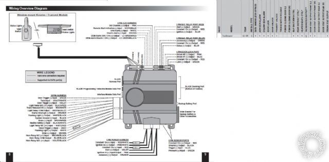
This is what how the module normally looks and the connections needed without the blade. Blade functions are in the box on the right.
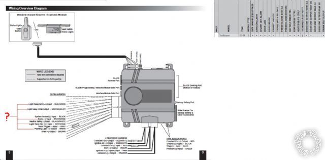
The bottom image is what i think i need to hook up. The wires i am unsure about are labeled with a question mark.
Also, with this alarm do i need a relay for accessory 2 or can i use the dome light wire? This is what the manual says
BLACK/ Red Wire - Light Relay N/O (+/-) Input
This circuit provides the constant feed input for the built-in 10 amp domelight relay. Specifically
the normally open pin (pin 87). This relay can be programmed via installer feature #2 for LOCK,
IGNITION, or ACCESSORY if need be.
CONNECTION: Connect this wire to constant power or chassis ground as needed for the chosen
function.
GREEN/ Violet Wire - Light Relay COM Output
This circuit provides the output for the built-in 10 amp domelight relay. Specifically the common
pin (pin 30). This relay can be programmed via installer feature #2 for LOCK, IGNITION, or ACCESSORY
if need be.
CONNECTION: Connect this wire to the vehicle circuit chosen to be driven. By default, connect to
the vehicles domelight circuit.
10 amps be enough?
Hey guys, im not trying to be a pest but i could really use some assistance. Thanks in advance.
Alarm/RS Module w/blade Vehicle wiring
6-pin main harness, all connections at ignition harness
Red Constant Power | Red
RED / White Constant Power | RED / White
Pink Ignition 1 | Pink
Pink/White ignition 2 | White
Orange accessory 1 | Orange
Violet start + | Yellow
18 Pin Secondary Harness
Green Door Trigger | Cut Handled by blade
Violet/White Tach input | Cut Handled by blade
Black Ground | Factory ground, cleaned
< color=#ff0000>Orange Starter interrupt
BROWN / Red brake + | Factory trailer prep controller box, white wire
BLACK/ White neutral safety | Factory Ground
Brown siren out | included siren +
WHITE/ black flashing light (-) out | grey/black at headlight switch
White flashing light (+) out | CUT
Gray hood trigger pin | Hood trigger pin (shouldnt leave disconnected, but can)
Violet door trigger + | Cut/handled by blade
RED / white trunk | cut
BLACK/ Red Wire Light Relay N/O (+/-) Input |12 volt constant from ignition harness
GREEN/ Violet Light Relay COM Output |Brown Accessory 2 in ignition harness
WHITE/ Red Light Relay N/C Input |CUT
Violet/Black Horn Relay N/O (+/-) Input
Blue/Black Horn Relay COM Output
BROWN / Black Horn Relay N/C Input
Blade hook up -
orange - Data | OBDII Purple
The part that is bolded, im not sure if i can do that or not, but it looks like it will work if i program the brain to use that as an accessory, can anyone elaborate?
Im not sure how to hook up the starter interupt or the horn
Also, is there anything that I am missing that needs to be connected?