2004 Chevy Colorado Security Bypass
Printed From: the12volt.com
Forum Name: Car Security and Convenience
Forum Discription: Car Alarms, Keyless Entries, Remote Starters, Immobilizer Bypasses, Sensors, Door Locks, Window Modules, Heated Mirrors, Heated Seats, etc.
URL: https://www.the12volt.com/installbay/forum_posts.asp?tid=133051
Printed Date: May 14, 2026 at 10:49 AM
Topic: 2004 Chevy Colorado Security Bypass
Posted By: jaxzin
Subject: 2004 Chevy Colorado Security Bypass
Date Posted: December 22, 2012 at 10:38 AM
Hi all,
A lot of you guys may know all about the Colorado and GM's Passlock II system. Basically the cars computer reads a resistance signal from the key cylinder in order to let the fuel injectors turn on. I have a 2004 Colorado with 46K miles. I've posted here before about help with battery issues and aftermarket alarm issues and have gotten the help I needed.
I am again asking for assistance. My truck is having problems with the Passlock system and to get it fixed the right way at the dealership it is right at about $700 which I can't afford at this time. The symptoms it has is the dreaded crank and no start with the Anti-Theft system light blinking on the dash. You wait 10 mins and it starts up with no problem. I have a 4 month old son now and I would hate to be in a position of an emergency and this issue happen.
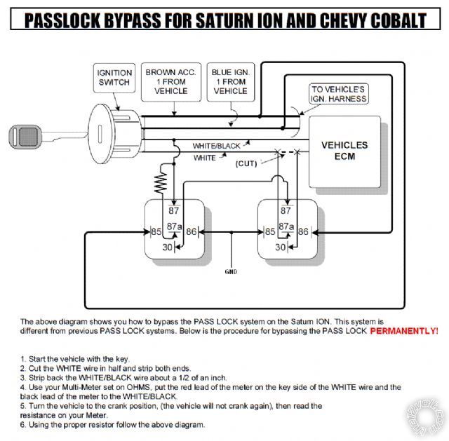
There is a way to bypass the passlock system for those using a remote start alarm like so.
Colorado remote start bypass
What I am needing help with is figuring out the relays without using a remote start alarm system. I have made a preliminary document which I think is correct but I wanted some experts opinions before I tried it. I can't post it here because it would violate the rules being how it can be used by someone to possibly disable a system from a vehicle that isn't theirs but it would take a long time.
If anyone can help me out I would send you the diagram offline or privately for review. Again thanks for all your help.
Replies:
Posted By: pentavolvo
Date Posted: December 22, 2012 at 11:39 AM
to permanently bypass just get resistor of correct value
cut white and blue wire and put resistor from ecm side to WHITE/ yellow wire
tape off the key side of WHITE/ blue wire
done
Posted By: kreg357
Date Posted: December 22, 2012 at 11:46 AM
As above, here is a link to a prior post on the Passlock2 immobilizer system.
https://www.the12volt.com/installbay/forum_posts.asp?tid=123309&KW=racing%5Fbidule
Of particular interest is the input from "racing_bidule". For additional security, you could include a hidden toggle switch with the resistor wire link. that would allow you to disable the Passlock2 bypass when necessary. ------------- Soldering is fun!
Posted By: jaxzin
Date Posted: December 22, 2012 at 2:38 PM
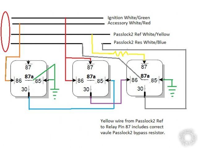
Thanks for the input guys. Being how this has already been posted before and some diagrams are already up I can post mine and I think it does not violate the forums rules.
Basically it's the same thing but with the addition of the second relay it allows the system to go back to stock configuration even though the wires are cut. Problem with leaving the key side just cut and taped is that you will have the security light flashing on the dash the whole time.
Here is what I modified from AudioVox. Basically its the same system but it omits the remote start / alarm system and just bypasses Passlock all together.

Posted By: ziggyb222
Date Posted: December 22, 2012 at 3:21 PM
I would make sure it is not the ignition switch itself.... there have been many problems with these switches... just did an install the other day and it was about the sixth one I was told the switch was replaced..... just a thought????
Posted By: jaxzin
Date Posted: December 22, 2012 at 3:38 PM
Sure. I can check that. maybe just replace it all together since its cheap.
Posted By: pentavolvo
Date Posted: December 22, 2012 at 4:22 PM
just doing resistor without a relay should not flash security light
Posted By: beegbie
Date Posted: December 22, 2012 at 5:53 PM
I don't think this is possible without a second switch. The resistor (passlock) value is only sent during crank. Your diagram has it feeding that value the whole time. It may work but your not duplicating what the ignition switch is/should be doing. In my opinion, wiring up a momentary switch to replace the +start signal from a remote start would be best. Use the diagram you have but use the momentary switch to trigger +12 volts to pin 86 of the relay on the left.
Posted By: jaxzin
Date Posted: December 22, 2012 at 11:13 PM
beegbie wrote:
I don't think this is possible without a second switch. The resistor (passlock) value is only sent during crank. Your diagram has it feeding that value the whole time. It may work but your not duplicating what the ignition switch is/should be doing. In my opinion, wiring up a momentary switch to replace the +start signal from a remote start would be best. Use the diagram you have but use the momentary switch to trigger +12 volts to pin 86 of the relay on the left.
Thanks for looking at the diagram. Would this way work?

Posted By: beegbie
Date Posted: December 23, 2012 at 6:41 AM
Nope. Same issue as above (it's actually the opposite of what we need). But you may be on to something. What we need here is for the relay on the left to only activate during crank. So if you keep pin 86 to accessory and move pin 85 to ignition, it may work. Assuming the accessory wire rests at enough ground to activate the relay.
Posted By: jaxzin
Date Posted: December 23, 2012 at 11:26 AM
beegbie wrote:
Nope. Same issue as above (it's actually the opposite of what we need). But you may be on to something. What we need here is for the relay on the left to only activate during crank. So if you keep pin 86 to accessory and move pin 85 to ignition, it may work. Assuming the accessory wire rests at enough ground to activate the relay.
So if we are looking for it to pass the resistance signal during crank then this will work. It's a bit crude but will work. I will also add diodes across 85 and 86.

Posted By: voltswagon
Date Posted: December 26, 2012 at 7:35 PM
What's RS brand and bypass module is installed?
I also have 05 Crewcab with Bulldog Deluxe and PLJX installed. No relay. Works great. ------------- Dont Drive and Text, but
Do Text Then Drive
Posted By: jaxzin
Date Posted: December 27, 2012 at 7:37 PM
Final diagram below. I think this nails it.

Although the colorado and the ION have the same system. I fail to see how this one works on his since the resistance is not being sent during crank.
Posted By: kreg357
Date Posted: December 27, 2012 at 8:07 PM
How about this?
------------- Soldering is fun!
Posted By: beegbie
Date Posted: December 30, 2012 at 1:00 PM
jaxzin wrote:
Final diagram below. I think this nails it.
Although the colorado and the ION have the same system. I fail to see how this one works on his since the resistance is not being sent during crank.
The diagram that you don't think will work is right. The relay on the left is on all the time except during crank. When the accessory drops out, the resistance is sent through the relay. I wish I had thought of that. Just wire it this way and it will work. Your diagram still does not activate the relay during crank.
Posted By: jaxzin
Date Posted: December 30, 2012 at 8:28 PM
technically both will work. On my schematic during crank 86 will drop out on the bottom relay which means 30 and 87a will be connected to ground and that will provide the ground to the resistor relay which will get 12v on 86 during crank.
The other schematic is correct also and used less parts. I'll go with that one and give it a try. I'll mock them up first and see how it goes.
|