f350 diesel remote starter
Printed From: the12volt.comForum Name: Car Security and Convenience
Forum Discription: Car Alarms, Keyless Entries, Remote Starters, Immobilizer Bypasses, Sensors, Door Locks, Window Modules, Heated Mirrors, Heated Seats, etc.
URL: https://www.the12volt.com/installbay/forum_posts.asp?tid=133119
Printed Date: May 15, 2026 at 6:07 PM
Topic: f350 diesel remote starter
Posted By: super03duty
Subject: f350 diesel remote starter
Date Posted: December 28, 2012 at 9:14 PM
Hello everyone. Im new to the page and was wondering if i may be able to find some specific installtion schematics.
I have an Autopage RS900 and I want to put it in my 2003 Ford F350 7.3L diesel. I have been thru the instruction manuall for hours multiple times and cross referencing to a schematic for my truck that i got off here. What im looking for is a very simple break down for my specific system to my specific truck.
Example: The pink wire of the system goes to the green wire at the brake switch. Or maybe something close. I really want to do this myself but i look at this system and its quite intimidating. My truck does not have a keyless entry now. I guess that matters for the door locks.
Please Any help is appreciated!!!
Replies:
Posted By: kreg357
Date Posted: December 29, 2012 at 7:30 AM
Below are several sources for wiring info for your truck.
Here is a link to Bulldog Security : https://www.bulldogsecurity.com/bdnew/vehiclewiringdiagrams.asp
Here is a link to Ready Remote : https://www.readyremote.com/main.asp?make=Ford&model=F350
Here is a link to AudioVox : https://techservices.audiovox.com/AccessRequest.aspx Sign-up & info is free.
You will probably notice discrepancies between them. That is why it is always best to use a Digital
Multi Meter to verify everything.
While there are some forum members that are familiar with your AutoPage system, I am not. Their
WEB site does not list the RS900 system, the closest is the C3-RS915LCD. Not sure if that is similar
to your RS900. It does appear that AutoPage gives a fairly in-depth, detailed description of each wire
and its' purpose.
A few things to point out...
Your will need two 30/40 Amp SPDT relays to make the necessary connections to the trucks power
door locks. An easier way is to obtain a DEI 451M door lock module ( ~$7 - $10 ). The 451M install
guide is available in the Downloads section.
While it probably doesn't, your truck might have a transponder based ignition immobilizer system.
The easy test is to get a $1.99 duplicate plain metal key made at the local hardware store and see if it
starts & runs the truck.
Diesels are a bit different for a R/S install. First there is the Diesel Wait to Start issue and then there
is the Tach Signal issue. Below are two notes from Bulldog Security :
NOTE #4: The DIESEL TACH wire is a GREEN / WHITE wire, located in a 5-pin harness held up
with tape behind the parking brake release.
NOTE #5: For WAIT TO START LIGHT, do not use the wire in the vehicle, use the 5,10,15 or 20
Second PROGRAMMABLE Wait To Start Timer on the Remote Starter
Here is a note from DEI on the Tach :
On diesel vehicles the tach wire is GREEN / WHITE in a 5 wire harness held up with white tape behind the
parking brake release. The tach wire on these vehicles may generate an unclean signal. Options maybe
to set the threshold jumper to on/low when programming tach in some Directed remote systems or use
part number 454T tach signal generator.
Here is DEI info on the Wait to Start :
Wait to start see Tech Doc 1091 ( Here is a link to this Tech Tip found in the Downloads section :
https://www.the12volt.com/installbay/file.asp?ID=1016 )
On the remote start, make sure to program the Accessory State During Wait To Start to ON.
It would make things easier for forum members to assist you, if you would take the time to list your
AutoPage RS900 harnesses, Pin #, Wire color / description so that we could easily cut & paste a response.
Example below :
6 Pin Heavy Gauge Harness
Red: Remote Start Power 1
Red: Remote Start Power 2
Violet: Starter (+) Output
Pink: Ignition 2 (+) Output
Yellow: Ignition 1 (+) Output
Brown: Acc/Heater (+) Output
-------------
Soldering is fun!
Posted By: super03duty
Date Posted: December 29, 2012 at 3:08 PM
https://www.autopageusa.com/resources/RS-900%20Install%20-0702011.pdf
That is the link for the Installation manual.
DEI 451? Where can i get these.
And no i dont have a transponder key I already made and extra key a while back and works great.
Why is it that the wait to start light doesnt work. Ive heard this before. just after 02. anything before that works fine. I have a good bit of electrical experience and it seems to me if you connect to the light the polarity would have to be reverse? Once the light is on it would be powering the system, but you would want the opposite? You would want the signal to go to the system once the light shuts off. I dont want a 30 sec timer year round. my light only stays on for about 15 seconds anyway. Is there a certain module or resistor that I can install?
Posted By: super03duty
Date Posted: December 29, 2012 at 3:20 PM
Posted By: kreg357
Date Posted: December 29, 2012 at 3:30 PM
No transponder is good. Saves time and money.
The DEI 451M module is available many places ( Amazon, EBay and various online stores ). Do an internet search on
"but Directed 451M". Prices range from $6 and up. It is even available at BestBuy for slightly more ( $10 ).
Can't say for sure on a F350, but some vehicles use Data instead of the typical +12V or Ground signal for instrument
panel control. If you have access to factory wiring diagrams, you might give it a try.
Another note on the ignition wires :
From Installer- The BLACK/ GREEN Accessory wire must be powered for diesel applications .
-------------
Soldering is fun!
Posted By: super03duty
Date Posted: December 29, 2012 at 6:53 PM
|
< size=3 face=Calibri>SYSTEM WIRES |
< size=3 face=Calibri>PIN# | < size=3 face=Calibri>TRUCK WIRE | < size=3 face=Calibri>LOCATION |
| < size=3 face=Calibri>H10. 20 PIN CONNECTOR | < size=3 face=Calibri> | < size=3 face=Calibri> | < size=3 face=Calibri> |
| < size=3 face=Calibri>Black / White Wire: (-) Neutral Safety Switc h Input | < size=3 face=Calibri>H1 | < size=3 face=Calibri>GROUND | < size=3 face=Calibri> |
| < size=3 face=Calibri>Black / Violet Wire: (-) 200 mA Channel 6 Programmable Output | < size=3 face=Calibri>H2 | < size=3 face=Calibri>NOT USED | < size=3 face=Calibri> |
| < size=3 face=Calibri>Pink Wire: 2-Step Unlock /Factory Disarm /Sensor By-pass | < size=3 face=Calibri>H3 | < size=3 face=Calibri>PINK/LTGREEN | < size=3 face=Calibri>KICK PANEL |
| < size=3 face=Calibri>White Wire: (-) 200mA Dome Light Control Output | < size=3 face=Calibri>H4 | < size=3 face=Calibri>BLK/LT BLUE | < size=3 face=Calibri>PASS KICK PANEL |
| < size=3 face=Calibri>Black / Red Wire: (-) 200 mA Channel 5 Programmable Output | < size=3 face=Calibri>H5 | < size=3 face=Calibri>NOT USED | < size=3 face=Calibri> |
| < size=3 face=Calibri>Bl ack / Green Wire: ( -) 20 0mA Chann el 4 Programmable Output | < size=3 face=Calibri>H6 | < size=3 face=Calibri>NOT USED | < size=3 face=Calibri> |
| < size=3 face=Calibri>Gray Wire: (-) 200mA Channel 2 (Trunk) Output | < size=3 face=Calibri>H7 | < size=3 face=Calibri>NOT USED | < size=3 face=Calibri> |
| < size=3 face=Calibri>Brown / White Wire: (-) 200mA Horn Output (P rogrammable) | < size=3 face=Calibri>H8 | < size=3 face=Calibri>BLUE | < size=3 face=Calibri>STEERING COLUMN |
| < size=3 face=Calibri>Yellow Wire: (-) 200mA Ig nition 3 Control Output | < size=3 face=Calibri>H9 | < size=3 face=Calibri>NOT USED | < size=3 face=Calibri> |
| < size=3 face=Calibri>Blue / Black Wire: (-) 200mA Accessory 2 Control Output | < size=3 face=Calibri>H10 | < size=3 face=Calibri>BLUE/LT GREEN | < size=3 face=Calibri>IGNITION HARNESS |
| < size=3 face=Calibri>Blue Wire:(-) Zone 2 Negative Hood/Trunk trigger | < size=3 face=Calibri>H20 | < size=3 face=Calibri> | < size=3 face=Calibri>HOOD SWITCH |
| < size=3 face=Calibri>White / Green Wire: (-) Diesel Wait-To-Start Input | < size=3 face=Calibri>H19 | < size=3 face=Calibri>VLT/OR-WT/LTGN | < size=3 face=Calibri> |
| < size=3 face=Calibri>White / Blue Wire: (-) Instant Start and Turn Off Input | < size=3 face=Calibri>H18 | < size=3 face=Calibri> | < size=3 face=Calibri> |
| < size=3 face=Calibri>Green Wire : Zone 3 (-) Negative Door Pin Trigger | < size=3 face=Calibri>H17 | < size=3 face=Calibri>NOT USED | < size=3 face=Calibri> |
| < size=3 face=Calibri>Violet Wire: Zone 3 (+) Positive Door Trigger | < size=3 face=Calibri>H16 | < size=3 face=Calibri>BLK/BLUE (+) | < size=3 face=Calibri>KICK PANEL |
| < size=3 face=Calibri>White / Red Wire: Tachometer Signal Input | < size=3 face=Calibri>H15 | < size=3 face=Calibri>WHT/PINK (-) | < size=3 face=Calibri>BCM |
| < size=3 face=Calibri>White / Black Wire: (-) Negative Hood Pin Safety Shut Down | < size=3 face=Calibri>H14 | < size=3 face=Calibri> | < size=3 face=Calibri>HOOD SWITCH |
| < size=3 face=Calibri>White / Violet Wire: (+) Brake Switch Shut Down Input | < size=3 face=Calibri>H13 | < size=3 face=Calibri>LT GREEN (+) | < size=3 face=Calibri>BRAKE SWITCH |
| < size=3 face=Calibri>Orange Wire: (-) 500mA Grounded Output When Armed | < size=3 face=Calibri>H12 | < size=3 face=Calibri>NOT USED | < size=3 face=Calibri> |
| < size=3 face=Calibri>Orange / White Wire: ( -) 20 0mA Grounded Output When Disar med | < size=3 face=Calibri>H11 | < size=3 face=Calibri>NOT USED | < size=3 face=Calibri> |
| < size=3 face=Calibri> | < size=3 face=Calibri> | < size=3 face=Calibri> | < size=3 face=Calibri> |
| < size=3 face=Calibri>H1 6 PIN HEAVY GAUGE WIRE HARNESS | < size=3 face=Calibri> | < size=3 face=Calibri> | < size=3 face=Calibri> |
| < size=3 face=Calibri>Red: Remote Start Power 1 | < size=3 face=Calibri> | < size=3 face=Calibri>YELLOW | < size=3 face=Calibri>IGNITION HARNESS |
| < size=3 face=Calibri>Red: Remote Start Power 2 | < size=3 face=Calibri> | < size=3 face=Calibri>GREEN/ VIOLET | < size=3 face=Calibri>IGNITION HARNESS |
| < size=3 face=Calibri>Violet: Starter (+) Output | < size=3 face=Calibri> | < size=3 face=Calibri>GREEN (12V START ONLY) | < size=3 face=Calibri>IGNITION HARNESS |
| < size=3 face=Calibri>Pink: Ignition 2 (+) Output | < size=3 face=Calibri> | < size=3 face=Calibri>RD/BLK (12V ON) | < size=3 face=Calibri>IGNITION HARNESS |
| < size=3 face=Calibri>Yellow: Ignition 1 (+) Output | < size=3 face=Calibri> | < size=3 face=Calibri>RD/LT GRN - WHT / YELLOW (12V ON) | < size=3 face=Calibri>IGNITION HARNESS |
| < size=3 face=Calibri>Brown: Acc/Heater (+) Output | < size=3 face=Calibri> | < size=3 face=Calibri>GRAY / YELLOW (12V ACC) | < size=3 face=Calibri>IGNITION HARNESS |
| < size=3 face=Calibri> | < size=3 face=Calibri> | < size=3 face=Calibri> | < size=3 face=Calibri> |
| < size=3 face=Calibri>H2 5 PIN WIRE HARNESS | < size=3 face=Calibri> | < size=3 face=Calibri> | < size=3 face=Calibri> |
| < size=3 face=Calibri>RED / White: Parking Light Relay Power Input | < size=3 face=Calibri> | < size=3 face=Calibri> | < size=3 face=Calibri> |
| < size=3 face=Calibri>White: Parking Light Relay Output | < size=3 face=Calibri> | < size=3 face=Calibri> | < size=3 face=Calibri> |
| < size=3 face=Calibri>Black: System Main Ground (-) | < size=3 face=Calibri> | < size=3 face=Calibri>GROUND | < size=3 face=Calibri> |
| < size=3 face=Calibri>Brown: Siren (+) Output | < size=3 face=Calibri> | < size=3 face=Calibri>TO THE SIREN | < size=3 face=Calibri> |
| < size=3 face=Calibri>Red: 12v + Battery Power | < size=3 face=Calibri> | < size=3 face=Calibri>CONS 12V |
THIS IS WHAT I HAVE SO FAR. PLEASE LET ME KNOW IF I AM WRONG ON ANYTHING AND IF YOU SEE A EMPTY SPOT PLEASE FILL ME IN.
THIS IS JUST A SPREAD SHEET I MADE TONIGHT COMPARING THE INSTALL MANUAL AND WIRING DIAGRAM OFF THIS SITE AND ANOTHER ONE.
Posted By: super03duty
Date Posted: December 29, 2012 at 6:54 PM
Posted By: kreg357
Date Posted: December 29, 2012 at 7:08 PM
How's this?
H1
Red: Remote Start Power 1
Red: Remote Start Power 2
Violet: Starter (+) Output
Pink: Ignition 2 (+) Output
Yellow: Ignition 1 (+) Output
Brown: Acc/Heater (+) Output
H2
RED / White: Parking Light Relay Power Input
Red: 12v + Battery Power
Brown: Siren (+) Output
Black: System Main Ground (-)
White: Parking Light Relay Output
H7
1. Blue Wire ( - ) Lock Pulse 1N4001 w/band towards RS900 to 451M
( + ) Unlock Pulse
3. Green Wire ( - ) Unlock Pulse 1N4001 w/band towards RS900 to 451M
(+) Lock Pulse
H8
Gray / Black Wire: ( -) 200mA Starter 2 Output
Brown / Black Wire: (- ) 500mA Grounded Output When Running
H10
1. Black / White Wire: (-) Neutral Safety Switch Input
2. Black / Violet Wire: (-) 200 mA Channel 6 Programmable Output
3. Pink Wire: 2-Step Unlock /Factory Disarm /Sensor By-pass
4. White Wire: (-) 200mA Dome Light Control Output
5. Black / Red Wire: (-) 200 mA Channel 5 Programmable Output
6. Black / Green Wire: ( -) 20 0mA Channel 4 Programmable Output
7. Gray Wire: (-) 200mA Channel 2 (Trunk) Output
8. Brown / White Wire: (-) 200mA Horn Output (Programmable)
9. Yellow Wire: (-) 200mA Ignition 3 Control Output
10. Blue / Black Wire: (-) 200mA Accessory 2 Control Output
11. Orange / White Wire: ( -) 20 0mA Grounded Output When Disarmed
12. Orange Wire: (-) 500mA Grounded Output When Armed
13. White / Violet Wire: (+) Brake Switch Shut Down Input
14. White / Black Wire: (-) Negative Hood Pin Safety Shut Down
15. White / Red Wire: Tachometer Signal Input
16. Violet Wire: Zone 3 (+) Positive Door Trigger
17. Green Wire : Zone 3 (-) Negative Door Pin Trigger
18. White / Blue Wire: (-) Instant Start and Turn Off Input
19. White / Green Wire: (-) Diesel Wait-To-Start Input
20. Blue Wire:(-) Zone 2 Negative Hood/Trunk trigger
-------------
Soldering is fun!
Posted By: super03duty
Date Posted: December 30, 2012 at 8:23 AM
Posted By: super03duty
Date Posted: December 30, 2012 at 8:46 AM
| < size=3 face=Calibri>SYSTEM WIRES | < size=3 face=Calibri>PIN# | < size=3 face=Calibri>TRUCK WIRE | < size=3 face=Calibri>LOCATION |
| < size=3 face=Calibri>H10. 20 PIN CONNECTOR | < size=3 face=Calibri> | < size=3 face=Calibri> | < size=3 face=Calibri> |
| < size=3 face=Calibri>Black / White Wire: (-) Neutral Safety Switc h Input | < size=3 face=Calibri>H1 | < size=3 face=Calibri>GROUND | < size=3 face=Calibri> |
| < size=3 face=Calibri>Black / Violet Wire: (-) 200 mA Channel 6 Programmable Output | < size=3 face=Calibri>H2 | < size=3 face=Calibri>NOT USED | < size=3 face=Calibri> |
| < size=3 face=Calibri>Pink Wire: 2-Step Unlock /Factory Disarm /Sensor By-pass | < size=3 face=Calibri>H3 | < size=3 face=Calibri>PINK/LTGREEN | < size=3 face=Calibri>KICK PANEL |
| < size=3 face=Calibri>White Wire: (-) 200mA Dome Light Control Output | < size=3 face=Calibri>H4 | < size=3 face=Calibri>BLK/LT BLUE | < size=3 face=Calibri>PASS KICK PANEL |
| < size=3 face=Calibri>Black / Red Wire: (-) 200 mA Channel 5 Programmable Output | < size=3 face=Calibri>H5 | < size=3 face=Calibri>NOT USED | < size=3 face=Calibri> |
| < size=3 face=Calibri>Bl ack / Green Wire: ( -) 20 0mA Chann el 4 Programmable Output | < size=3 face=Calibri>H6 | < size=3 face=Calibri>NOT USED | < size=3 face=Calibri> |
| < size=3 face=Calibri>Gray Wire: (-) 200mA Channel 2 (Trunk) Output | < size=3 face=Calibri>H7 | < size=3 face=Calibri>NOT USED | < size=3 face=Calibri> |
| < size=3 face=Calibri>Brown / White Wire: (-) 200mA Horn Output (P rogrammable) | < size=3 face=Calibri>H8 | < size=3 face=Calibri>BLUE | < size=3 face=Calibri>STEERING COLUMN |
| < size=3 face=Calibri>Yellow Wire: (-) 200mA Ig nition 3 Control Output | < size=3 face=Calibri>H9 | < size=3 face=Calibri>NOT USED | < size=3 face=Calibri> |
| < size=3 face=Calibri>Blue / Black Wire: (-) 200mA Accessory 2 Control Output | < size=3 face=Calibri>H10 | < size=3 face=Calibri>BLUE/LT GREEN | < size=3 face=Calibri>IGNITION HARNESS |
| < size=3 face=Calibri>Blue Wire:(-) Zone 2 Negative Hood/Trunk trigger | < size=3 face=Calibri>H20 | < size=3 face=Calibri> | < size=3 face=Calibri>HOOD SWITCH |
| < size=3 face=Calibri>White / Green Wire: (-) Diesel Wait-To-Start Input | < size=3 face=Calibri>H19 | < size=3 face=Calibri>VLT/OR-WT/LTGN | < size=3 face=Calibri> |
| < size=3 face=Calibri>White / Blue Wire: (-) Instant Start and Turn Off Input | < size=3 face=Calibri>H18 | < size=3 face=Calibri> | < size=3 face=Calibri> |
| < size=3 face=Calibri>Green Wire : Zone 3 (-) Negative Door Pin Trigger | < size=3 face=Calibri>H17 | < size=3 face=Calibri>NOT USED | < size=3 face=Calibri> |
| < size=3 face=Calibri>Violet Wire: Zone 3 (+) Positive Door Trigger | < size=3 face=Calibri>H16 | < size=3 face=Calibri>BLK/BLUE (+) | < size=3 face=Calibri>KICK PANEL |
| < size=3 face=Calibri>White / Red Wire: Tachometer Signal Input | < size=3 face=Calibri>H15 | < size=3 face=Calibri>WHT/PINK (-) | < size=3 face=Calibri>BCM |
| < size=3 face=Calibri>White / Black Wire: (-) Negative Hood Pin Safety Shut Down | < size=3 face=Calibri>H14 | < size=3 face=Calibri> | < size=3 face=Calibri>HOOD SWITCH |
| < size=3 face=Calibri>White / Violet Wire: (+) Brake Switch Shut Down Input | < size=3 face=Calibri>H13 | < size=3 face=Calibri>LT GREEN (+) | < size=3 face=Calibri>BRAKE SWITCH |
| < size=3 face=Calibri>Orange Wire: (-) 500mA Grounded Output When Armed | < size=3 face=Calibri>H12 | < size=3 face=Calibri>NOT USED | < size=3 face=Calibri> |
| < size=3 face=Calibri>Orange / White Wire: ( -) 20 0mA Grounded Output When Disar med | < size=3 face=Calibri>H11 | < size=3 face=Calibri>NOT USED | < size=3 face=Calibri> |
| < size=3 face=Calibri> | < size=3 face=Calibri> | < size=3 face=Calibri> | < size=3 face=Calibri> |
| < size=3 face=Calibri>H1 6 PIN HEAVY GAUGE WIRE HARNESS | < size=3 face=Calibri> | < size=3 face=Calibri> | < size=3 face=Calibri> |
| < size=3 face=Calibri>Red: Remote Start Power 1 | < size=3 face=Calibri> | < size=3 face=Calibri>YELLOW | < size=3 face=Calibri>IGNITION HARNESS |
| < size=3 face=Calibri>Red: Remote Start Power 2 | < size=3 face=Calibri> | < size=3 face=Calibri>GREEN/ VIOLET | < size=3 face=Calibri>IGNITION HARNESS |
| < size=3 face=Calibri>Violet: Starter (+) Output | < size=3 face=Calibri> | < size=3 face=Calibri>GREEN (12V START ONLY) | < size=3 face=Calibri>IGNITION HARNESS |
| < size=3 face=Calibri>Pink: Ignition 2 (+) Output | < size=3 face=Calibri> | < size=3 face=Calibri>RD/BLK (12V ON) | < size=3 face=Calibri>IGNITION HARNESS |
| < size=3 face=Calibri>Yellow: Ignition 1 (+) Output | < size=3 face=Calibri> | < size=3 face=Calibri>RD/LT GRN - WHT / YELLOW (12V ON) | < size=3 face=Calibri>IGNITION HARNESS |
| < size=3 face=Calibri>Brown: Acc/Heater (+) Output | < size=3 face=Calibri> | < size=3 face=Calibri>GRAY / YELLOW (12V ACC) | < size=3 face=Calibri>IGNITION HARNESS |
| < size=3 face=Calibri> | < size=3 face=Calibri> | < size=3 face=Calibri> | < size=3 face=Calibri> |
| < size=3 face=Calibri>H2 5 PIN WIRE HARNESS | < size=3 face=Calibri> | < size=3 face=Calibri> | < size=3 face=Calibri> |
| < size=3 face=Calibri>RED / White: Parking Light Relay Power Input | < size=3 face=Calibri> | < size=3 face=Calibri> | < size=3 face=Calibri> |
| < size=3 face=Calibri>White: Parking Light Relay Output | < size=3 face=Calibri> | < size=3 face=Calibri> | < size=3 face=Calibri> |
| < size=3 face=Calibri>Black: System Main Ground (-) | < size=3 face=Calibri> | < size=3 face=Calibri>GROUND | < size=3 face=Calibri> |
| < size=3 face=Calibri>Brown: Siren (+) Output | < size=3 face=Calibri> | < size=3 face=Calibri>TO THE SIREN | < size=3 face=Calibri> |
| < size=3 face=Calibri>Red: 12v + Battery Power | < size=3 face=Calibri> | < size=3 face=Calibri>CONS 12V |
Posted By: super03duty
Date Posted: December 30, 2012 at 9:09 AM
H10. 20 PIN CONNECTOR
Black / White Wire: (-) Neutral Safety Switc h Input H1 GROUND
Black / Violet Wire: (-) 200 mA Channel 6 Programmable Output H2 NOT USED
Pink Wire: 2-Step Unlock /Factory Disarm /Sensor By-pass H3 PINK/LTGREEN KICK PANEL
White Wire: (-) 200mA Dome Light Control Output H4 BLK/LT BLUE PASS KICK PANEL
Black / Red Wire: (-) 200 mA Channel 5 Programmable Output H5 NOT USED
Bl ack / Green Wire: ( -) 20 0mA Chann el 4 Programmable Output H6 NOT USED
Gray Wire: (-) 200mA Channel 2 (Trunk) Output H7 NOT USED
Brown / White Wire: (-) 200mA Horn Output (P rogrammable) H8 BLUE STEERING COLUMN
Yellow Wire: (-) 200mA Ig nition 3 Control Output H9 NOT USED
Blue / Black Wire: (-) 200mA Accessory 2 Control Output H10 BLUE/LT GREEN IGNITION HARNESS
Blue Wire:(-) Zone 2 Negative Hood/Trunk trigger H20 HOOD SWITCH
White / Green Wire: (-) Diesel Wait-To-Start Input H19 VLT/OR-WT/LTGN
White / Blue Wire: (-) Instant Start and Turn Off Input H18
Green Wire : Zone 3 (-) Negative Door Pin Trigger H17 NOT USED
Violet Wire: Zone 3 (+) Positive Door Trigger H16 BLK/BLUE (+) KICK PANEL
White / Red Wire: Tachometer Signal Input H15 WHT/PINK (-) BCM
White / Black Wire: (-) Negative Hood Pin Safety Shut Down H14 HOOD SWITCH
White / Violet Wire: (+) Brake Switch Shut Down Input H13 LT GREEN (+) BRAKE SWITCH
Orange Wire: (-) 500mA Grounded Output When Armed H12 NOT USED
Orange / White Wire: ( -) 20 0mA Grounded Output When Disarmed H11 NOT USED
H1 6 PIN HEAVY GAUGE WIRE HARNESS
Red: Remote Start Power 1 YELLOW IGNITION HARNESS
Red: Remote Start Power 2 GREEN/ VIOLET IGNITION HARNESS
Violet: Starter (+) Output GREEN (12V START ONLY) IGNITION HARNESS
Pink: Ignition 2 (+) Output RD/BLK (12V ON) IGNITION HARNESS
Yellow: Ignition 1 (+) Output RD/LT GRN - WHT / YELLOW (12V ON) IGNITION HARNESS
Brown: Acc/Heater (+) Output GRAY / YELLOW (12V ACC) IGNITION HARNESS
H2 5 PIN WIRE HARNESS
RED / White: Parking Light Relay Power Input
White: Parking Light Relay Output
Black: System Main Ground (-) GROUND
Brown: Siren (+) Output TO THE SIREN
Red: 12v + Battery Power CONS 12V
Posted By: super03duty
Date Posted: December 30, 2012 at 9:10 AM
Finnaly. Let me know what you think and please give me some input on the wires i am missing
Posted By: kreg357
Date Posted: December 30, 2012 at 7:02 PM
SYSTEM WIRES PIN# TRUCK WIRE LOCATION
H10. 20 PIN CONNECTOR
Black / White Wire: (-) Neutral Safety Switc h Input H1 GROUND
Black / Violet Wire: (-) 200 mA Channel 6 Programmable Output H2 NOT USED
Pink Wire: 2-Step Unlock /Factory Disarm /Sensor By-pass H3 PINK/LTGREEN KICK PANEL
White Wire: (-) 200mA Dome Light Control Output H4 BLK/LT BLUE PASS KICK PANEL
Black / Red Wire: (-) 200 mA Channel 5 Programmable Output H5 NOT USED
Bl ack / Green Wire: ( -) 20 0mA Chann el 4 Programmable Output H6 NOT USED
Gray Wire: (-) 200mA Channel 2 (Trunk) Output H7 NOT USED
Brown / White Wire: (-) 200mA Horn Output (P rogrammable) H8 BLUE STEERING COLUMN
Yellow Wire: (-) 200mA Ig nition 3 Control Output H9 NOT USED
Blue / Black Wire: (-) 200mA Accessory 2 Control Output H10 To extra Relay Pin 85 *** See wiring below
Blue Wire:(-) Zone 2 Negative Hood/Trunk trigger H20 Not Used
White / Green Wire: (-) Diesel Wait-To-Start Input H19 VLT/OR-WT/LTGN
White / Blue Wire: (-) Instant Start and Turn Off Input H18 Not Used
Green Wire : Zone 3 (-) Negative Door Pin Trigger H17 NOT USED
Violet Wire: Zone 3 (+) Positive Door Trigger H16 BLK/BLUE (+) KICK PANEL
White / Red Wire: Tachometer Signal Input H15 WHT/PINK (-) BCM
White / Black Wire: (-) Negative Hood Pin Safety Shut Down H14 HOOD SWITCH
White / Violet Wire: (+) Brake Switch Shut Down Input H13 LT GREEN (+) BRAKE SWITCH
Orange Wire: (-) 500mA Grounded Output When Armed H12 NOT USED
Orange / White Wire: ( -) 200mA Grounded Output When Disarmed H11 NOT USED
H1 6 PIN HEAVY GAUGE WIRE HARNESS
Red: Remote Start Power 1 YELLOW IGNITION HARNESS
Red: Remote Start Power 2 GREEN/ VIOLET IGNITION HARNESS
Violet: Starter (+) Output GREEN (12V START ONLY) IGNITION HARNESS
Pink: Ignition 2 (+) Output RD/BLK (12V ON) IGNITION HARNESS
Yellow: Ignition 1 (+) Output RD/LT GRN or WHT / YELLOW (12V ON) IGNITION HARNESS
Brown: Acc/Heater (+) Output GRAY / YELLOW (12V ACC) IGNITION HARNESS
H2 5 PIN WIRE HARNESS
RED / White: Parking Light Relay Power Input with Red to +12V
White: Parking Light Relay Output Brown @ Headlight Switch
Black: System Main Ground (-) GROUND
Brown: Siren (+) Output TO THE SIREN
Red: 12v + Battery Power CONS 12V
H7 451M
1. Blue Wire ( - ) Lock Pulse 1N4001 w/band towards RS900 Blue
( + ) Unlock Pulse
3. Green Wire ( - ) Unlock Pulse 1N4001 w/band towards RS900 Green
(+) Lock Pulse
Extra ACC2 Relay
Relay Pin 85 to RS900 H10 Pin 10 Blue / Black Wire
Relay Pin 86 and 87 to +12V constant
Relay Pin 30 to F350 Acc2 BLUE/LT GREEN @ ignition harness
Relay Pin 87a not used - insulate
-------------
Soldering is fun!
Posted By: super03duty
Date Posted: December 30, 2012 at 7:54 PM
Great!!! Thanks alot for your input.
One more question though. I have 2 Acc wires in my harness at the ignition. Why cant i use both? why the relay?
Posted By: kreg357
Date Posted: December 30, 2012 at 8:21 PM
Not sure I understand the question.
The R/S unit can supply two Ignitions, one Starter and one Accessory ( @ +12V 30 Amp ). Your truck has two Ignitions, one Starter and two Accessories. The extra relay is so the trucks second Accessory has power during a remote start.
-------------
Soldering is fun!
Posted By: super03duty
Date Posted: December 30, 2012 at 9:27 PM
The truck has 2 acc wires.
acc 1 is gray / YELLOW
acc 2 is blue/light green
The RS system has 2 acc wires
H10 #10 is the blue/black wire labeled ACC2
H1 #6 is the brown wire labeled ACC1
My question is if there are 2 of each why cant i use them? Why do i have to run a relay? I feel like such a moron with this project. What has always made sense to me about electrical has gone out the window with this thing. This is the newest truck Ive ever owned and Im still learning all the little stupid things ford did with it. I relplaced the motor in this thing by myself and im strugling with a fricken remote start!!!!
From what I am reading on your last post is that you have to manually power the Acc 2 in the ignition harness with the relay.
Posted By: kreg357
Date Posted: December 30, 2012 at 9:44 PM
Ah, a little gotcha..
The trucks ignition wires are all high current positive (+) circuits. The H1 connector outputs high current (+) positive outputs. A good match.
The H10 Blue/Black wire is marked as a (-) output. Not a good match. Also notice the gauge of this wire as compared to the H1 wires. We use a relay controlled by the H10 (-) ACC2 wire to supply the trucks Accessory2 wire with the high current (+) positive power it needs.
We learn something new everyday. 
-------------
Soldering is fun!
Posted By: super03duty
Date Posted: December 31, 2012 at 11:09 AM
WHERE CAN I MOUNT THE SHOCK SENSOR? CAN I JUST GROUND THE WIRE FOR THE HOOD SWITCH? i CANT FIND A SPOT FOR IT THAT THE SWITCH ACUTALLY HITS THE HOOD WHEN IT COMES DOWN.
i HAVE THE DEI 451M'S ON THE WAY FOR THE DOOR LOCKS. I HAVE PRETTY MUCH EVERYTHING ELSE HOOKED UP. I DECIDED JUST TO USE THE BUILT IN TIMER FOR THE WAIT TO START SINCE I CANT FIND THE CORRECT WIRE. EVERYONE SAYS SOMETING DIFFERENT.
Posted By: super03duty
Date Posted: December 31, 2012 at 11:11 AM
Posted By: kreg357
Date Posted: December 31, 2012 at 7:53 PM
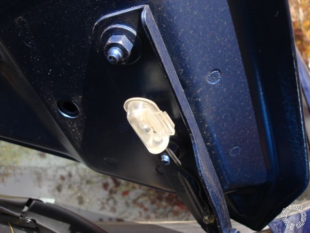
The Hood Pin is a very valuable safety and really should be used. Sometimes you have to be real creative in finding a
way to mount it. Here is a recent post on this subject : https://www.the12volt.com/installbay/forum_posts.asp~TID~132487~PN~1
If aren't too worried about the alarm aspect of this switch ( and having the Hood Pin trigger when the hood is lifted 1/2 inch )
you can use a tilt switch mounted on the hinge. It is easier to locate and mount and it lasts a whole lot longer. Here is one
mounted in a Dodge Caravan :
Ford has a bad habit of running the Horn wire in with the air bag wires. Be very careful when testing and use only a DMM, never
a test light, in that area.
-------------
Soldering is fun!
Posted By: super03duty
Date Posted: January 01, 2013 at 12:54 PM
Ok, so the install was a success to a degree. the remote start works as expected. I have not hooked up the lock/unlock wires since i dont have the DEI451m parts yet.
Heres my issue. I hit the lock/arm button on the remote and it tells me the drivers door is open. You open the door and lock/arm the system and it shows closed. I know the wires are connected corectly. (You and I have gone rounds aobut that!!LOL) In the list I made the neg door pin trigger is not used. Is this supposed to be that way? I just never found a neg trigger on any of the list i looked at. Am i hooked the the wrong truck wire or should the neg door trigger wire be hooked to the blk/blue in the truck?
The other Issue is that if i hit the unlock button on the door the alarm goes off and i have to unhook the batteries to get it to stop. The remote is unresponsive. It does not go off if you hit the lock button on the door just the unlock. Now remember i have not hooked up the wires from the H7 plug since i dont have the parts. Should i just wait and see what happens when i do get them hooked up or did i do something wrong?
Posted By: kreg357
Date Posted: January 01, 2013 at 1:55 PM
Just noticed this. Disconnect the H10/4 White wire if it is going to the same place as the H10/16 Violet wire. You will need a relay to
change the H10/4 polarity to the (+) the truck needs.
H10. 20 PIN CONNECTOR
Black / White Wire: (-) Neutral Safety Switc h Input H1 GROUND
Black / Violet Wire: (-) 200 mA Channel 6 Programmable Output H2 NOT USED
Pink Wire: 2-Step Unlock /Factory Disarm /Sensor By-pass H3 PINK/LTGREEN KICK PANEL
White Wire: (-) 200mA Dome Light Control Output H4 BLK/LT BLUE *************** PASS KICK PANEL
Black / Red Wire: (-) 200 mA Channel 5 Programmable Output H5 NOT USED
Bl ack / Green Wire: ( -) 20 0mA Chann el 4 Programmable Output H6 NOT USED
Gray Wire: (-) 200mA Channel 2 (Trunk) Output H7 NOT USED
Brown / White Wire: (-) 200mA Horn Output (P rogrammable) H8 BLUE STEERING COLUMN
Yellow Wire: (-) 200mA Ig nition 3 Control Output H9 NOT USED
Blue / Black Wire: (-) 200mA Accessory 2 Control Output H10 To extra Relay Pin 85 *** See wiring below
Blue Wire:(-) Zone 2 Negative Hood/Trunk trigger H20 Not Used
White / Green Wire: (-) Diesel Wait-To-Start Input H19 VLT/OR-WT/LTGN
White / Blue Wire: (-) Instant Start and Turn Off Input H18 Not Used
Green Wire : Zone 3 (-) Negative Door Pin Trigger H17 NOT USED
Violet Wire: Zone 3 (+) Positive Door Trigger H16 BLK/BLUE (+) ************** KICK PANEL
White / Red Wire: Tachometer Signal Input H15 WHT/PINK (-) BCM
White / Black Wire: (-) Negative Hood Pin Safety Shut Down H14 HOOD SWITCH
White / Violet Wire: (+) Brake Switch Shut Down Input H13 LT GREEN (+) BRAKE SWITCH
Orange Wire: (-) 500mA Grounded Output When Armed H12 NOT USED
-------------
Soldering is fun!
Posted By: super03duty
Date Posted: January 01, 2013 at 4:43 PM
can i set it up the same way that you told me to set up the ACC2? I have an extra relay.
As far as the door locks and the alarm going off????
Posted By: kreg357
Date Posted: January 01, 2013 at 5:04 PM
As far as the relay for Dome Light Supervision, yes same wiring.
Relay Pin 86 and 87 to +12V constant fused @ 5 Amps
Relay Pin 85 to H10/4 White
Relay Pin 30 to Truck BLACK/ Light Blue (+)
Does the truck have the domelight fade out when the door is closed? That delay can cause problems when arming
the alarm. Maybe programming Alarm Feature A - 3 would help. ( Not too familiar with your R/S system.)
-------------
Soldering is fun!
Posted By: super03duty
Date Posted: January 01, 2013 at 6:27 PM
No it does not have the fade dome lights. can i jump power to the relay from the other installed relay or should i run its own separate power wires?
Posted By: kreg357
Date Posted: January 01, 2013 at 6:44 PM
You can jump it. It draws very little current.
If the R/S is armed and you get the Dome Light to come on, it thinks a door has been opened and sets off the alarm. The R/S is using the Dome Light as a trigger wire for the alarm, if this wire goes to +12 volts, it sets off the alarm.
-------------
Soldering is fun!
Posted By: super03duty
Date Posted: January 03, 2013 at 4:43 PM
Posted By: kreg357
Date Posted: January 03, 2013 at 6:13 PM
-------------
Soldering is fun!
Posted By: super03duty
Date Posted: January 04, 2013 at 11:27 AM
Posted By: kreg357
Date Posted: January 04, 2013 at 1:02 PM
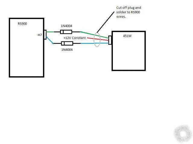
My suggestion for the diodes was due tho the RS900's door lock outputs. They are what I call "push-pull".
When the RS900 outputs a Lock pulse, it is actually a (-) pulse followed by a (+) pulse. Most R/S units only
output a simple (-) pulse. The diode will block the (+) pulse and prevent it from causing damage or confusion
to the unit receiving this signal. The 451M module kit includes only resistors. The resistors are used
for "one-wire" door lock systems. You won't need them. The correct diode would be a 1N4001, 1N4004 or 1N4007.
These are the most commonly available. They are all one amp diodes with different Peak / RMS reverse voltage
ratings. Here is a link to a Data Sheet on these diodes : https://www.diodes.com/datasheets/ds28002.pdf
Here is a diagram of the R/S to 451M connections :
-------------
Soldering is fun!
Posted By: super03duty
Date Posted: January 05, 2013 at 4:13 PM
So i have some bad news. Today was the first day that i have driven my truck since my install because i am doing some body work also. I turned on the blower motor on the way to work and i get there, shut the truck off and my blower is still going!!! even with the key off. What did i do now? I am going to work on it tomm so any ideas and input would be helpfull. I guess i will check my wiring for the about the 5th time just to be sure nothing is hooked up wrong. And can I get the diodes from say radio shack or where are they readily available?