8th civic 2011 compustar cm6200
Printed From: the12volt.com
Forum Name: Car Security and Convenience
Forum Discription: Car Alarms, Keyless Entries, Remote Starters, Immobilizer Bypasses, Sensors, Door Locks, Window Modules, Heated Mirrors, Heated Seats, etc.
URL: https://www.the12volt.com/installbay/forum_posts.asp?tid=133308
Printed Date: April 06, 2026 at 1:57 PM
Topic: 8th civic 2011 compustar cm6200
Posted By: coho
Subject: 8th civic 2011 compustar cm6200
Date Posted: January 15, 2013 at 8:26 AM
so i'm shamefully finally getting around to installing a compustar cm 6200 into an 8th chassis 2011 civic (no factory alarm) that's been sitting in the box for over a year now (life gets busy, i don't know how guys with kids manage).
I feel pretty prepared so far with the exception of 4 lingering questions i'd appreciate any help with:
1) the control unit has the option of doing tachless, alternator sense, or coil/injector sense and some vehicles/chassis seem to "prefer" one connection versus another. the compustar install manual and some people says injector, two local installers say they only do tachless, and one particular experience forum member says the 8th civic prefers alternator? is this simply a case of "more than one way to skin a cat"? or is there actually a "best way" for this car? a common consensus would help...
2) the vehicle wiring info specifies both a "parking light" and "low current parking light" wire....seeing as some people experience fuse issues in some vehicle, i'm assuming it'd be preferable to use the low current parking light wire? or does it matter?
3)in preparation for the install i examined the engine compartment to plan where to mount the hood pin. I've noticed that the late model civics have a lot of plastic trim on the perimeter which complicates mounting the pin to bare sheet metal. I did however notice two through holes on either front corner which might work, but they're at a slight angle...they both had the letters "U" and "D" marked in the plastic. I also read one comment on these forums about connecting the hood pin wire to the existing latch mechanism? (if i understood correctly?) If so, how would one go about doing that? I'd also like to hear any experience/thoughts/comments on how others mounted their pins.
Thank you for your time,
Coho
Replies:
Posted By: shortcircuit161
Date Posted: January 15, 2013 at 9:07 AM
1) I always use a tach connection to an injector (uncommon wire) if the data bypass module doesn't provide a tach signal. I would never use alternator signal on this car since some models actually shut off the alternator to help with fuel economy when it's idling.
2) Parking lights is your preference but I always try to use negative (low current) parking lights since it's less power being used overall by the remote starter.
3) If equipped, you can tie into the factory hood switch wire or you can get it from the data bypass module (depending on which module you use).
Directwire shows the hood pin wire as
Hood Pin lt. blue - dash fuse box, blue 21 pin plug (G), pin 13
-------------
Posted By: coho
Date Posted: January 15, 2013 at 9:45 PM
3) If equipped, you can tie into the factory hood switch wire or you can get it from the data bypass module (depending on which module you use).
Directwire shows the hood pin wire as
Hood Pin lt. blue - dash fuse box, blue 21 pin plug (G), pin 13[/QUOTE]
i was wanting to try and preferably use this wire - but i was wondering...would the wire/switch mechanism be present in my car if it didn't come with a factory alarm? (canadian models don't) if it didn't, i wouldn't be able to...but i guess i might be able to buy it from honda
Posted By: shortcircuit161
Date Posted: January 15, 2013 at 10:22 PM
I believe that's the only time that the factory hood pin would be on there but i'm not completely certain.
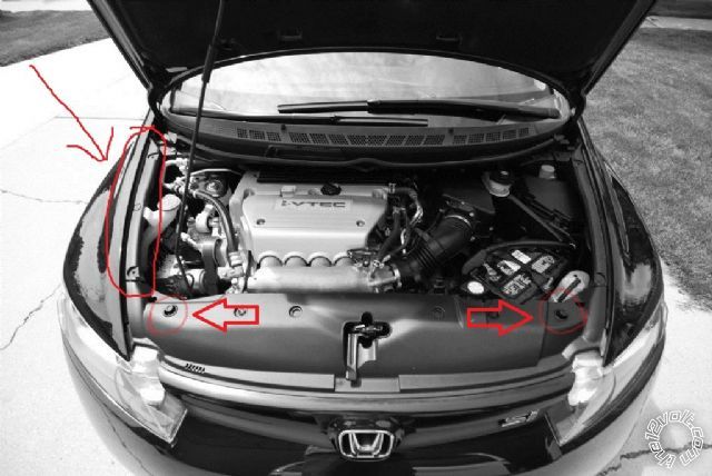
You can also try removing the plastic cover at the front of the engine bay to see what's underneath (it's only held down with a couple of plastic clips). You can find a good spot underneath and drill a hole in the metal frame and extend the aftermarket hood pin switch so that it goes past the plastic cover too (you will have to drill a slightly bigger hole in that plastic cover to allow the pin switch to stick out). I would check the farther edges closer to the headlights. Or possibly up the side trim pieces.
 -------------
Posted By: coho
Date Posted: January 15, 2013 at 11:32 PM
hi frank,
thanks for the response...and the photo
you see the two clips you circled? if you look closely there are preexisting holes in both the sheet metal and the plastic that i was thinking of using....although the holes in each material are ever so slightly offset..
i just wonder what the "U" and "D" markings beside the holes are for?
Posted By: coho
Date Posted: January 15, 2013 at 11:43 PM
edit: i meant to say that there's preexisting holes
"on either side" of those clips you circled...
Posted By: shortcircuit161
Date Posted: January 16, 2013 at 11:08 AM
I don't know what the U or D are for. I would guess Up and Down? But for what exactly, I don't know.
i would check underneath to see if it seems like it would block anything or if in doubt, use the side trim area. Slightly offset is not a big issue as long as it pushes the pin switch enough to allow the remote starter to work.
-------------
Posted By: coho
Date Posted: January 20, 2013 at 10:40 PM
thanks for the feedback thus far...
as far as the hoodpin goes I ended up substituting the conventional spring loaded hoodpin for a mercury switch - worked great!
However, I began my install this afternoon and after stopping for the day, 3 questions arose:
-I have to remove the underdash micu fuse box to gain access to the backside...but i noticed that the fastener for the fuse box is a strange one...for anyone who has removed it...how did you do so?
-my civic has a 2nd accessory wire so i had to install the supplied additional relay to connector CN1; pin 5. In hindsight I noticed that both the pin 5 lead AND the relay lead were fused...so when they're connected I had a lead that was double fused. Did I screw this up or is this just the way compustar designed the wiring?
-when connecting the blade AL wiring harness I noticed that there were no bare wire ends - the harness had a different connector on each end of the harness. Seeing as I couldn't find any information about it anywhere, I'm assuming that this design is to accommodate compatibility with 2 different styles of connectors in different control units and you simply cut the connector off of the end which your control unit does NOT have?
Thanks again,
coho
Posted By: offroadzj
Date Posted: January 21, 2013 at 6:09 AM
- Can't help you about the MICU fuse box.
- A double fuse won't hurt anything... it's just one more fuse you will have to check if you ever have issues.
- I'm guessing you are talking about the white, WHITE/ red, and WHITE/ black wires? If so, some of the harnesses had a connected within the first 3 inches or so of those wires, and others had it at the end. Just cut the blue 3-pin connector off and wire as needed.
The only issue with a mercury switch is that it will disable the remote start if you ever park on a hill. That may or may not affect you, but it's something to keep in mind.
-------------
Kenny
Owner / Technician
KKD Garage LLC
Albany, NY 12205
Posted By: coho
Date Posted: January 21, 2013 at 8:22 AM
offroadzj wrote:
- Can't help you about the MICU fuse box.
- A double fuse won't hurt anything... it's just one more fuse you will have to check if you ever have issues.
- I'm guessing you are talking about the white, WHITE/ red, and WHITE/ black wires? If so, some of the harnesses had a connected within the first 3 inches or so of those wires, and others had it at the end. Just cut the blue 3-pin connector off and wire as needed.
The only issue with a mercury switch is that it will disable the remote start if you ever park on a hill. That may or may not affect you, but it's something to keep in mind.
yeah, i agreed with this - just the weird result made me think the wiring logic was wrong. If i'm correct, vehicle 12v enters the one CN1 pin 5 lead connected to 12v and then parallels out through the 2nd cn5 pin 1 lead bringing 12v to pins 86 & 87 of the 2nd accessory relay. Pin 86 of the 2nd accessory relay is connected to CN2 pin 9 which is ground switched by the controller. when the ground is switched it activates the relay bringing the 12v across to pin 87 of the relay which powers the 2nd accessory circuit?
Makes me wonder why there's none of this relay hoopla for the first accessory circuit which is connected directly? It looks like they did this in the cm6300 controller, no?
Concerning the Blade harness, actually there's the blue 3 pin connector you speak of on both ends of the wires, AND there's a black 20 pin connector - it's just that each connector is different. I noticed that one of the connectors is compatible with CN3 on the controller, while the other connector is compatible with ??? Either way, if i don't cut one of the connectors off, there is no way to physically interface the wires with the vehicle wiring!?
Funny you should mention the parking on a hill thing. I realized this after installing the merc switch. I'm ok with that given the tradeoff of no additional holes in my car.
Posted By: offroadzj
Date Posted: January 21, 2013 at 9:02 AM
The CM6200 has internal relays for the ignition, accessory, and starter, but any 2nd ignition / accessory / starter requires the external relay. The new brains that are supposed to be release hopefully soon (but I can't find any information on them) supposedly will have internal relays for extra circuits.
The black connector is the main connector. DO NOT CUT THAT OFF. That will connect into the Compustar brain. The 3 pin blue connector is the one that just gets cut off. I'm not 100% sure what the point of that connector is.
-------------
Kenny
Owner / Technician
KKD Garage LLC
Albany, NY 12205
Posted By: coho
Date Posted: January 21, 2013 at 6:16 PM
that's just it - there's 2 black female 20 pin connectors; one connector at each end of the wires. The connectors are identical in pinout, just a different size & shape of connector?
Of the 20 wires, 17 travel uninterrupted between the two black connectors, while the other 3 are pigtailed a short distance and then terminated with the blue female 3 pin connector of which you speak of, and then there is a supplied matching male connector with longer leads for those 3 wires. These 3 wires are fine to use because they are empty wire leads, but the remaining 17, you'd have to choose one connector and cut the other one off in order to have some bare wire leads....
Posted By: offroadzj
Date Posted: January 21, 2013 at 7:41 PM
Sounds like a fluke harness. I'd pick the harness that plugs into the brain and then cut the other one off.
-------------
Kenny
Owner / Technician
KKD Garage LLC
Albany, NY 12205
|