2004 tundra double cab wiring pin/plug?
Printed From: the12volt.com
Forum Name: Car Security and Convenience
Forum Discription: Car Alarms, Keyless Entries, Remote Starters, Immobilizer Bypasses, Sensors, Door Locks, Window Modules, Heated Mirrors, Heated Seats, etc.
URL: https://www.the12volt.com/installbay/forum_posts.asp?tid=133446
Printed Date: April 10, 2026 at 4:05 PM
Topic: 2004 tundra double cab wiring pin/plug?
Posted By: bpowa
Subject: 2004 tundra double cab wiring pin/plug?
Date Posted: January 28, 2013 at 2:32 AM
Hi. I am trying to install viper 5704. However when I spliced the wire for h3/1. I tapped to the 12v constant and shorted the wire to ground now the car won't start. I currently tapped a hot wire from the Battery to the wire. I checked all the fuses. Under the hood and driver panel and all are fine.
How else can I trace this wire?
Its the constant 12v WHITE/ red.
Also can anyone provide a pin/plug wiring diagram. Picture. So I can make sure the rest of the wires are tapped correctly?
I'm in a jam. :( TIA
-------------
Larry
Replies:
Posted By: metz35
Date Posted: January 28, 2013 at 6:05 AM
Check every fuse for continuity . It may look fine when it's actually blown. It's more than likely gonna be a high amperage fuse. 30 amps on up. My recommendation is stop what your doing until your truck starts again.
Posted By: offroadzj
Date Posted: January 28, 2013 at 6:07 AM
You most likely did just blow a fuse. And as metz said, it will normally be a higher amperage fuse. Check everything with a DMM either by continuity across the fuse or by testing for 12v on either terminal of the fuse with the ignition turned on. Visually checking a fuse does not always work.
-------------
Kenny
Owner / Technician
KKD Garage LLC
Albany, NY 12205
Posted By: Chris Luongo
Date Posted: January 28, 2013 at 7:10 AM
The fuses that feed constant power to the ignition switch on Toyotas are often labeled AM1 and AM2, usually under the hood. Check those especially carefully.
Posted By: howie ll
Date Posted: January 28, 2013 at 9:02 AM
They should be on the main battery POS wiring.
Alternatively at engine bay fuse box adjacent to input wire from battery, Alternatively labelled "Battery" or "IGN.".
-------------
Amateurs assume, don't test and have problems; pros test first. I am not a free install service.
Read the installation manual, do a search here or online for your vehicle wiring before posting.
Posted By: bpowa
Date Posted: January 28, 2013 at 10:16 AM
Guys thanks a bunch, I guess I did miss one fuse.. I know the wire is a 25a lead.. Looked under the fuse box and verified.. The 12v wire is fixed.
However I am hoping for someone to provide me with a diagram of the plugs.
I just want to make sure I am tapping into the correct wire of the Becu, door triggers, tachometer etc..
some of the wires are close to the same colors and I have a slight color deficiency.
Im sure I got the remote start wires tapped correctly. However I tested it and I got a "remote start error".. The alarm is not completely installed. So I will look into that later.
I tried searching all over the net, even looked at chiltons at autoparts store. No one has a pin plug diag.
Something like post #24 would be great.. https://www.toyotanation.com/forum/103-3rd-4th-generation-1992-1996-1997-2001/424981-2000-solara-2-2-wont-start-2.html
Thanks
-------------
Larry
Posted By: chev104275
Date Posted: January 28, 2013 at 10:35 AM
You shouldn't need a pinout. Did you verify everything with a DMM ?
-------------
If i Can't Install it I Don't need it Joe
Posted By: bpowa
Date Posted: January 28, 2013 at 11:17 AM
well this is the first time I installed an alarm system.. I hate electrical, but I feel that its one of the only things I never tinkered with in cars.
Normally there are pinouts for every car I had, but this model I cannot find anything.
I use a test light for the wires, and check conduit by activating it like brake pedal, horn, etc..
However I do want to verify the Tachometer from the ECU/ECM.
It would make things more clear for me with Pinouts. and put me at ease for a first timer..
I also read I need to diode each door lock trigger and want to add some relays and diodes for the door lock unlock. I would like a pin before soddering.
-------------
Larry
Posted By: soundnsecurity
Date Posted: January 28, 2013 at 12:00 PM
DO NOT USE A TEST LIGHT IN A CAR TO INSTALL AN ALARM!!!!!!!
you can easily destroy your trucks electronics or deploy the airbags if you test the wrong wire!
you need a digital multi meter to test wires for alarms. even if you have a wiring diagram for your truck you still need to test to make sure the wires are correct. if you dont know how to test the wires then you shouldnt be installing an alarm. you cant just assume the diagram is correct because they can be wrong or there might be more wires of the same color at the same spot so its impossible to tell without testing with a meter.
sorry if this is a bit harsh but you need to be honest with yourself, if electrical is not your thing then why take the chance on your own car just to save some money.
if you still want to do it yourself then we can find a diagram but you have to test your wires before you tap onto them.
-------------
Posted By: bpowa
Date Posted: January 28, 2013 at 12:35 PM
Hey I appreciate the info.. As mentioned.. It is not about saving money.
The time I put into research and and install is worth more than the 150 bucks I can pay someone.
I will use a digital meter, but I also would like a pinout.
I am not new to cars I was a mechanic by trade. however when working in shops we always had alldata and mitchell handy for diagrams. So I know not to tap into the yellow airbag wire.
Anyone can help with that would be appreciated..
-------------
Larry
Posted By: soundnsecurity
Date Posted: January 28, 2013 at 12:52 PM
ok well at least you know something. still, electrical is a far cry from mechanical and the two fields usually dont get along. cars, especially new cars, are easy to mess up and expensive to fix.
2004 Toyota Tundra:
Security
WIRE COLOR POLARITY LOCATION
Battery WHITE/ BLUE OR WHITE/ RED (+) IGNITION SWITCH HARNESS
Ignition 1 BLACK/ RED (+) IGNITION SWITCH HARNESS
Starter 1 BLACK/ WHITE (+) IGNITION SWITCH HARNESS
All Door Trigger BLUE/BLACK (-) KEY CYL. LIGHT
LF Latch LT.GREEN/ BLACK (-) DRIVER'S KICK PANEL
RF Latch GREY/RED (-) BLACK 14 PIN CONNECTOR IN PASSENGER'S KICK
LR Latch RED / WHITE (-) UNDER DRIVER'S SILL PLATE
RR Latch RED / WHITE (-) BLACK 14 PIN CONNECTOR IN PASSENGER'S KICK
Trunk Trigger RED / BLUE (-) PIN SWITCH OR LIGHT IN TRUNK
Hood Trigger RED / WHITE OR RED / BLUE (-) PIN SWITCH OR THEFT MOD/ECU
Alarm Disarm DISARMS WITH UNLOCK*
FACTORY THEFT ECU UNDER DRIVER SIDE DASH.
Alarm Arm ARMS WITH LOCK
Parking Lights GREEN (+) DRIVER KICK OR FUSE BOX
Low Crr Pk Lights GREEN (-) STEERING COLUMN HARNESS
Convenience
WIRE COLOR POLARITY LOCATION
Headlights-Lo RED / BLUE (-) AT VEHICLE LIGHT SWITCH
Wipers-Lo BLUE/BLACK (-) AT VEHICLE WIPER MOTOR
Remote Start
WIRE COLOR POLARITY LOCATION
Battery WHITE/ BLUE OR WHITE/ RED (+) IGNITION SWITCH HARNESS
Ignition 1 BLACK/ RED (+) IGNITION SWITCH HARNESS
Ignition 2 BLACK / YELLOW (+) IGNITION SWITCH HARNESS
Accessory 1 PINK (+) IGNITION SWITCH HARNESS
Starter 1 BLACK/ WHITE (+) IGNITION SWITCH HARNESS
Key Sense YELLOW* (-) IGNITION HARNESS
* USING THE ACTIVE OUTPUT WIRE FROM REMOTE START UNIT TO THIS WIRE WILL DIARM FACTORY ALARM WITHOUT UNLOCKING DOORS.
Tachometer GREEN/ BLACK (AC) AT IGNITION COIL
CAN ALSO BE FOUND AS A WHITE/ BLUE 31 PIN CONNECTOR AT THE ECM PIN 5
Speed Sense GREEN/ ORANGE OR PURPLE / WHITE (AC) 35 PIN CONNECTOR AT THE ECM PIN 17 OR BACK OF FUSE BOX
Parking Lights GREEN (+) DRIVER KICK OR FUSE BOX
Low Crr. Pk Lights GREEN (-) STEERING COLUMN HARNESS
Brake Lights GREEN / WHITE (+) AT SWITCH ABOVE BRAKE PEDAL
Reverse Lights RED / BLACK (+) IN HARNESS IN DRIVERS KICKPANEL
Horn BLACK / YELLOW (-) IN STEERING COLUMN HARNESS
Modules
WIRE LOCATION
Module 1 ECM LOCATED BEHIND THE GLOVE BOX
Doorlocks/Windows
WIRE COLOR POLARITY LOCATION
Power Unlock LT.GREEN/ RED (-) IN DRIVERS DOOR
SEE TOYOTA/LEXUS LOCK SENSE VEHICLE DOCUMENT.
PowerLock LT.GREEN/ BLACK (-) IN DRIVERS DOOR
FOR TOYOTA LOCK INTEGRATION
Child Safety Wire RED / YELLOW (-) IN DRIVERS DOOR
Driver Mtr Unlock RED / BLACK (REV) IN HARNESS IN DRIVERS KICKPANEL
Driver Mtr Lock BLUE/RED (REV) IN HARNESS IN DRIVERS KICKPANEL
Pas Mtr Unlock BLUE/BLACK (REV) IN HARNESS IN DRIVERS KICKPANEL
LF Window Up RED (REV) IN DRIVER'S DOOR
LF Window Dn GREEN (REV) IN DRIVER'S DOOR
RF Window Up RED (REV) IN PASSENGER'S DOOR
RF Window Dn GREEN (REV) IN PASSENGER'S DOOR
LR Window Up WHITE/ RED (REV) UNDER DRIVER'S SILL PLATE
LR Window Dn BLUE (REV) UNDER DRIVER'S SILL PLATE
RR Window Up GREEN/ YELLOW (REV) BLACK 14 PIN CONNECTOR IN DRIVER'S KICK PANEL
RR Window Dn BLUE (REV) BLACK 14 PIN CONNECTOR IN DRIVER'S KICK PANEL
-------------
Posted By: soundnsecurity
Date Posted: January 28, 2013 at 12:58 PM
not the best wiring diagram but audiovox is usually alright. still test every wire you hook up to.
the door locks need to be ran into the drivers door, i cant get to the notes for the door lock interface but someone else might be able to post the diagram for interfacing toyota locks inside the door. last time i did a sequoia around that year/model all i had to do was tap another wire at the switch that needs to see ground when you unlock the truck. not %100 sure though because its been a while since ive had to do this.
-------------
Posted By: howie ll
Date Posted: January 28, 2013 at 1:03 PM
"I also read I need to diode each door lock trigger and want to add some relays and diodes for the door lock unlock. I would like a pin before soddering." (SIC)
Why? No relays needed on this install.
Power lock = GREEN/ black NEG (-) driver kick, white 12 pin plug, pin 9.
Pwr. unlock = RED / Yellow NEG (-) driver kick, white 12 pin plug, pin 8.
Tach = Black (V6), blue/white (V8) instrument cluster, brown 13 pin plug, pin 4.
Door trigger = WHITE/ blue (-) all doors, driver kick, grey 10 pin plug, pin 8 or white 4 pin plug, pin 4.
I've given you the dome light supervision wire as your door trigger since if your dome light stays on for about a minute after shutting the doors and or goes out immediately on locking them, you won't need dome supervision, it's already there or need to connect to more than that wire.
I'm giving you this info but I strongly suggest you have it installed professionally.
Being a mechanic certainly doesn't qualify you as a sparks and look at what's happened already.
It's perfectly OK to use a test light if you've been doing this for over 40 years,
but I never use anything but a meter on a vehicle new to me.
Is there a factory alarm?
-------------
Amateurs assume, don't test and have problems; pros test first. I am not a free install service.
Read the installation manual, do a search here or online for your vehicle wiring before posting.
Posted By: howie ll
Date Posted: January 28, 2013 at 1:06 PM
Sorry S&S, you've done a Kregg on me!
I used DEI but the standard access cab, don't have a go, never seen one in Europe.
-------------
Amateurs assume, don't test and have problems; pros test first. I am not a free install service.
Read the installation manual, do a search here or online for your vehicle wiring before posting.
Posted By: howie ll
Date Posted: January 28, 2013 at 1:14 PM
Go with soundnsecurity's colours,I had the wrong body shape. DEI gives tach as WHITE/ blue ECM, far right plug, pin 5.
-------------
Amateurs assume, don't test and have problems; pros test first. I am not a free install service.
Read the installation manual, do a search here or online for your vehicle wiring before posting.
Posted By: bpowa
Date Posted: January 28, 2013 at 2:05 PM
ok Now im kinda confused.. At the bottom of the second post.. It says I need to diode all 4 doors and..
Add relays for the door lock unlock.
https://www.the12volt.com/installbay/forum_posts.asp~TID~85910
This is why I would like a picture diagram with legends for each pin of the harness connectors to make sure...
-------------
Larry
Posted By: soundnsecurity
Date Posted: January 28, 2013 at 2:06 PM
toyota doorlock diagram
this is a link to the diagram of what you need to do at the drivers master switch.
the door trigger can be done in a few ways, you can use the dome light to tell the alarm when the doors are open or you can used each individual doorpin. if you use each doorpin then you will have to add a diode on each wire going to the alarm. this keeps the doorpins from interfering with each other. if you use the domelight then you dont need diodes -------------
Posted By: howie ll
Date Posted: January 28, 2013 at 2:13 PM
Ref: Door trigger read again what I said about the domelight staying on. That's how I do Toyotas. If it (the dome light) does what I said, no diodes needed.
Why are you even bothering if you don't read or understand what we said?
-------------
Amateurs assume, don't test and have problems; pros test first. I am not a free install service.
Read the installation manual, do a search here or online for your vehicle wiring before posting.
Posted By: bpowa
Date Posted: January 28, 2013 at 3:12 PM
lol sorry man I am new to this.. My dome light does go out after a minute after shutting all the doors.. So to be clear. All I have to do is wire the door trigger from the alarm module and splice it into the dome light supervision with no diodes?
-------------
Larry
Posted By: soundnsecurity
Date Posted: January 28, 2013 at 3:55 PM
what howie meant was that if the dome light goes out when you lock the doors then it would make a good door trigger. if it stays on even after the door locks for a few seconds then it will cause the alarm to report an error when you arm the alarm. if the light stays on after lock then the alarm will see it as the door is still open and it wont arm until the domelight goes out. usually its not a huge deal but it can be annoying
-------------
Posted By: howie ll
Date Posted: January 28, 2013 at 4:34 PM
1-4 second delay is acceptable and won't trigger say DEI product (10 second settle time).
Toyota instant.
BMW Instant but needs diodes on trunk light + side.
Honda, about 3 seconds.
VW Instant.
All vehicles where you go to the dome light, no diodes and no supervision needed.
-------------
Amateurs assume, don't test and have problems; pros test first. I am not a free install service.
Read the installation manual, do a search here or online for your vehicle wiring before posting.
Posted By: bpowa
Date Posted: January 28, 2013 at 5:15 PM
Thanks guys.. Yes the dome light goes out when I lock the door instantly. I soddered 4 diodes for nothing..
I wonder when it was mentioned in other threads to do so..
Well at least i Can use the diodes for the door lock/unlock relay.
Thanks S&S for the relay diagram..
-------------
Larry
Posted By: howie ll
Date Posted: January 28, 2013 at 5:25 PM
Don't worry mate, you aren't the first and certainly not the last to fall into that, as in my bottom line it's called assuming without finding out for oneself.
I bought this up about 7 years ago when I did a Toyota after about a 5 year gap and noticed the dome light.
When DEI was still Clifford in Europe, there were two vehicles, BMW E46 and Ford Mondeo (Edge) that had the most thorough V2.0 revisions, yes take a bow Howard. Actually it was a Euro Corolla called the Auris in western Europe, built in the UK (the version built in Turkey for the M/East is still called the Corolla) and I couldn't find those separate door triggers, do I thought let's look at the dome light.
In fact to take this further I did an RX, couldn't be bothered with 1070 found the lock and unlock (-) wires in the door at the motor loom, connected directly and it worked first time. I also discovered that if you extended the lock pulse time you also had roof and window close.
Hence my original post on this thread questioning the need for relays and diodes.
-------------
Amateurs assume, don't test and have problems; pros test first. I am not a free install service.
Read the installation manual, do a search here or online for your vehicle wiring before posting.
Posted By: bpowa
Date Posted: January 28, 2013 at 6:18 PM
"I did an RX, couldn't be bothered with 1070 found the lock and unlock (-) wires in the door at the motor loom, connected directly and it worked first time."
This is interesting. Is there a way I can test the wire to verify both the lock/unlock (-)?
I prefer it over relays..
-------------
Larry
Posted By: howie ll
Date Posted: January 28, 2013 at 6:22 PM
Go to the wires given as lock and unlock, ground each in turn.
One point. The reason for the 1070 is "lock detect" that may not be present on Euro models.
-------------
Amateurs assume, don't test and have problems; pros test first. I am not a free install service.
Read the installation manual, do a search here or online for your vehicle wiring before posting.
Posted By: bpowa
Date Posted: January 28, 2013 at 7:54 PM
howie ll wrote:
Go to the wires given as lock and unlock, ground each in turn.
One point. The reason for the 1070 is "lock detect" that may not be present on Euro models.
Well I did actually hooked up the wiries to the door loom. It does nothing. The alarm works but not the door locks.. I basically have no time until the weekend to finish it.
I went to 3 different places. and looked for the #775 relay and to my disbelief no one has it.. ------------- Larry
Posted By: soundnsecurity
Date Posted: January 28, 2013 at 8:16 PM
the relay you need is a normal SPDT 12v relay. any audio shop should have them or radioshack as a last resort. its not called a 775, i dont even know where that came from.
-------------
Posted By: howie ll
Date Posted: January 29, 2013 at 2:29 AM
X 2 with sns, also known as Bosch/Tycho cube, standard automotive relay.
-------------
Amateurs assume, don't test and have problems; pros test first. I am not a free install service.
Read the installation manual, do a search here or online for your vehicle wiring before posting.
Posted By: bpowa
Date Posted: January 30, 2013 at 10:52 AM
Thanks for the Dome light info on the door triggers.. It works great. I got a question about the relay doorlock/unlock diagram.
Do I need to preform this diagram on each door or just the driver side?
-------------
Larry
Posted By: howie ll
Date Posted: January 30, 2013 at 11:18 AM
Only the driver's door.
-------------
Amateurs assume, don't test and have problems; pros test first. I am not a free install service.
Read the installation manual, do a search here or online for your vehicle wiring before posting.
Posted By: bpowa
Date Posted: January 30, 2013 at 11:53 AM
Awesome.. Howie what do you think I should add to the alarm?
Glass break, proximity sensor, or tilt sensor..
I was thinking tilt or proximity. not both.
My truck is nothing special.. no wheels.. I haul my motorcycles to the track overnight trips, and have my work laptop, etc.. in the cab.. its the main reason, I got the alarm.
-------------
Larry
Posted By: howie ll
Date Posted: January 30, 2013 at 12:00 PM
Prox*, or even a single zone prox in the load area.
If you have standard wheels, no point in having a tilt sensor.
*If you go for a dual zone, try and mount it inside to the rear roof, should cover your load area. You will have to extend the 4 wires.
-------------
Amateurs assume, don't test and have problems; pros test first. I am not a free install service.
Read the installation manual, do a search here or online for your vehicle wiring before posting.
Posted By: bpowa
Date Posted: February 02, 2013 at 10:30 PM
Well. The alarm works. Engine start works. But I an not getting signal from the parking lights. I tapped into th headlight ( green) wire. But no flashes. Also i hooked up a relay according to the diagram, into the door loom. Door unlocks not does not lock.
Any ideas?
-------------
Larry
Posted By: howie ll
Date Posted: February 03, 2013 at 9:31 AM
Make sure the jumper fuse is set for NEG output on the white wire and test.
-------------
Amateurs assume, don't test and have problems; pros test first. I am not a free install service.
Read the installation manual, do a search here or online for your vehicle wiring before posting.
Posted By: bpowa
Date Posted: February 03, 2013 at 2:54 PM
The jumper works. Lights work. When I jumper to positive.
. However the door lock still only locks but don't unlock. It's kicking my ass struggling with it. Any other tips?
-------------
Larry
Posted By: bpowa
Date Posted: February 04, 2013 at 4:33 PM
Anyone out there for input?
-------------
Larry
Posted By: soundnsecurity
Date Posted: February 04, 2013 at 5:08 PM
what wire did you use for the lock function? did you test the wire with a volt meter? how did you test it and what kind of reading do you get?
-------------
Posted By: bpowa
Date Posted: February 04, 2013 at 5:30 PM
I used the lt.GREEN/ black for the lock wire. the wire tested 1.625v it spikes up slightly to 1.645v or so when I press the lock button.
Is there another way I should be testing it?
-------------
Larry
Posted By: soundnsecurity
Date Posted: February 04, 2013 at 7:33 PM
a tiny voltage spike is not what you are looking for when you test lock wires. if they are negative trigger then you are looking for the wire to rest at 5 or 12 volts depending on the system and the wire will drop close to 0 volts when you press the lock switch. this is with the black lead of the meter hooked to a ground source and using the red lead to test the wire. some lock systems need to be tested by turning the key in the door's key cylinder and not the switch.
not only that, did you use the relay and diodes that are shown in the lock diagram? the wires you are looking for are at the drivers door switch but they need to be wired exactly like in the diagram or it wont work.
-------------
Posted By: bpowa
Date Posted: February 04, 2013 at 10:42 PM
Ok. But I think the lock spiked up. More than the negative. I think it maybe a alarm programing
The wires are tapped from the door lock switch. Meaning the wires under the driver side door lock button and power window. Is this correct?
I wires the door just like the diagram.
I thought i programmed the alarm to double pulse unlock. Is this correct?
-------------
Larry
Posted By: bpowa
Date Posted: February 05, 2013 at 6:21 PM
Well I cannot find anything on this truck searching the net. As if no one ever really did a DIY..
Sound like everyone is using a bypass. I would have went with one if I knew ahead of time.
I dont want to install a bypass when I only have one issue I have to complete..
-------------
Larry
Posted By: soundnsecurity
Date Posted: February 05, 2013 at 7:08 PM
can you take some pictures of how you wired the locks at the switch? it would help me figure it out for you. do the locks work like normal with the switch.
-------------
Posted By: howie ll
Date Posted: February 06, 2013 at 1:09 AM
Disconnect the lock and unlock leads from your R/S. Take your DMM,set it to 20VDC, place the red probe on a constant source and place the black probe on the lock and unlock wires in sequence then lock and unlock with the remote.
You should get a 12VDC reading each time.
If not the R/S is faulty.
If you do, then the R/S is OK, so repeat this test at the joins in the door.
If not your wiring is faulty, bad join, open circuit etc.
If OK then ground each join in turn.
If that locks and unlocks the vehicle, look again at how you did the relay, diode position, etc.
I'm assuming soldered joints or all bets are off.
-------------
Amateurs assume, don't test and have problems; pros test first. I am not a free install service.
Read the installation manual, do a search here or online for your vehicle wiring before posting.
Posted By: bpowa
Date Posted: February 06, 2013 at 1:28 PM
here is a picture from door panel control..
please let me know if I have it correct.. I will try to find time to test the wires..
-------------
Larry
Posted By: bpowa
Date Posted: February 06, 2013 at 1:46 PM
sorry.. I cant post pic..
here is a link
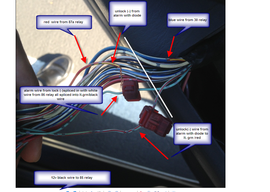 ------------- Larry
Posted By: soundnsecurity
Date Posted: February 06, 2013 at 2:02 PM
your negative unlock that goes to the RED / yellow wire needs to go the the other side of the wire when it gets split with the relay. other than that the only other problem i see is that you are using T-taps for your connections, this could cause a connection problem because they dont contact the wire tight enough sometimes. and make sure your diodes are facing the right way, the stripe needs to go towards the alarm.
-------------
Posted By: bpowa
Date Posted: February 06, 2013 at 2:45 PM
Well from my picture above the controller is to the left side, and the motor is to the right.. Its the opposite to the diagram.. Can you confirm?
Those t taps were there prior. But I use them to tap in temporary.
I will make solid connections when all the wiring is correct and tuck neatly.
-------------
Larry
Posted By: howie ll
Date Posted: February 06, 2013 at 4:54 PM
And you will get constantly recurring problems with those T-taps.
Loose them and solder now.
-------------
Amateurs assume, don't test and have problems; pros test first. I am not a free install service.
Read the installation manual, do a search here or online for your vehicle wiring before posting.
Posted By: soundnsecurity
Date Posted: February 06, 2013 at 4:58 PM
no, if you look at the diagram carefully it has the motor AND switch on the same side. it says motor on top and switch on the bottom. the part that says motor is a separate part of the diagram
-------------
Posted By: bpowa
Date Posted: February 06, 2013 at 5:28 PM
Yes.. I will try that out.. Diagram is better than the other 1070 I saw. But For the armature installer like myself its hard to determine.
Thanks I will try that out.. Hopefully in the next couple days..
-------------
Larry
Posted By: soundnsecurity
Date Posted: February 06, 2013 at 5:44 PM
yea, i didnt really notice that it had the motor in the diagram or i would have pointed it out. there is not reason at all to have the motor on that diagram because it has nothing to do with what you have to do. sorry.
-------------
Posted By: bpowa
Date Posted: February 08, 2013 at 9:56 PM
I tested the wires and switched the diodes like you said. Now the unlocks work. Single and double pulse. The only thing that does not work is it does not lock.
I tested the wires for lock and they have signal to them from the alarm box and the door lock control from the truck. There is signal from the lt GREEN/ blk wire also. But no action for it to lock. As if i tapped the incorrect wire. I know its something simple and its frustrating. Any other thoughts?
-------------
Larry
Posted By: soundnsecurity
Date Posted: February 09, 2013 at 1:00 AM
may need to double pulse the lock. will it lock if all of the doors are closed? many cars have a safety feature that stops it from locking on the first press if a door is open or key is in the ignition.
-------------
Posted By: bpowa
Date Posted: February 09, 2013 at 1:18 AM
I tried programing it all 4 features. Also pressed the door sensor bottom in to mimic door close. It does nothing. But its strange that there is a signal. On the lock wires and the lt grn/ black wire.
The lock bottom works. I did notice when I disconnected the wire from the 86 relay that is tapped to the lock wire. The door locks. So it maybe a wiring issue. But I feel i tried everything. Unless it needs another relay?
-------------
Larry
Posted By: soundnsecurity
Date Posted: February 09, 2013 at 12:18 PM
if it works when you remove power from the relay then that means your relay is wired wrong. make sure you have the wires on 30 and 87a(center pin) of the relay. the reason for the relay is to open the RED / yellow wire when you try to lock the doors. if you have the wire to 87 instead of 87a then you are doing the exact opposite, closing the RED / yellow wire, when you try to lock and this would explain why the lock doesnt work.
dont feel bad, relays can be frustrating if you dont have a good understanding of exactly what they do. they are hard to troubleshoot without knowing how they work. but i guess it could be possibly to have a bad relay, although it is really rare. if your wires are on the right pins like i said, then swap out the relay and try again.
-------------
Posted By: bpowa
Date Posted: February 09, 2013 at 9:25 PM
No. When I disconnected the 86 relay to the right. The door locked.
87a and 30. Are correct. I did not use 87 for the power. I even tried growning the yellow wire. It did nothing.
Should I try 87 instead of 87a to the door ecu?
-------------
Larry
Posted By: soundnsecurity
Date Posted: February 10, 2013 at 8:05 AM
ok, so with 86 unhooked, everything works? even the switch? if the answer is yes then try leaving the relay out of the install. put the RED / yellow back together and see if it works.
-------------
Posted By: bpowa
Date Posted: February 10, 2013 at 10:45 AM
No everything works with relay except door lock. But when I disconnect the 86 wire only. The door locks. I don't know what means besides the lock actually works.
So with out the relay do i just tap the door lock/unlock to the lt GREEN/ blk and lt GREEN/ red. With diodes?
-------------
Larry
Posted By: bpowa
Date Posted: February 15, 2013 at 8:22 AM
Ok guys. Here is an update. I wish i had seen when i searched. Save yourself the hassle and order a xko1 xpress bypass module. Or any other bypass for the door locks. It's cleaner and less splice. Everything works now.
-------------
Larry
|