1996 ford bronco factory keyless entry?
Printed From: the12volt.com
Forum Name: Car Security and Convenience
Forum Discription: Car Alarms, Keyless Entries, Remote Starters, Immobilizer Bypasses, Sensors, Door Locks, Window Modules, Heated Mirrors, Heated Seats, etc.
URL: https://www.the12volt.com/installbay/forum_posts.asp?tid=133503
Printed Date: April 12, 2026 at 1:50 PM
Topic: 1996 ford bronco factory keyless entry?
Posted By: 1966fskbk
Subject: 1996 ford bronco factory keyless entry?
Date Posted: February 02, 2013 at 10:07 PM
Hi,.
I have a 1996 Ford Bronco, I just bought it and thought I would put a new stereo and alram. I bought a Clifford 520.4x Responder LE alarm and want to install it. However, I just noticed after taking a part the dash I see a stock ford keyless entry. Identifying numbers on it are CANADA: 1422 K1308 / FSERIES / 19597 (biggest numbers on it) / with F3VG-15K602-AC above it.
Question: Do I just follow the normal installation on the Clifford quick ref guide and don't worry about that being there? I have no FOBs for the old thing nor did I even know it was there.
OR
Do I use the wires coming out of that module?? How do I identify those for use? Does this make everything way more complicated?
OR
??
Thank you all .. I am lost. ------------- CloudCasters
Replies:
Posted By: soundnsecurity
Date Posted: February 02, 2013 at 10:14 PM
i wouldnt use the same wires for power and ground, i would do those to the ignition harness as you would normally do on a fresh install and then if you can find other connections like locks or the doorpin or maybe the parking lights then i would use those wires just to make it easy.
i would also unplug the factory keyless module if you dont have the keypads for it.
-------------
Posted By: Ween
Date Posted: February 02, 2013 at 11:02 PM
unplugging the factory keyless on an older ford vehicle may disable the power door locks. the keyless module often has the relays that perform the switching of polarity for the door lock motors. the factory keyless i believe has door lock and unlock, door trigger, horn and parking lights...all useable with the aftermarket product. pretty sure i have wiring diagram of factory system if you need more assistance.
Posted By: 1966fskbk
Date Posted: February 02, 2013 at 11:23 PM
Hello,
So what I think I am hearing WEEN is to use the wires located at the factory keyless entry instead of hunting for them in the kick and column for at least parking lights, locks, horn. - Yes?
You have the wire diag for that ford keyless entry I have - please yes I would very much like to have it.
What is door trigger?
Yes - that question most definietely marked me as NOOB!
Thank! ------------- CloudCasters
Posted By: Ween
Date Posted: February 02, 2013 at 11:41 PM
i'll get it for you tomorrow. the door trigger is used as an input for the alarm...so when the door opens the alarm goes off.
Posted By: 1966fskbk
Date Posted: February 03, 2013 at 12:16 AM
Also-
when we say "...all useable with the aftermarket product" .... does that mean I connect to the outgoing wires exiting from the OEM KE connecting to the devices (horn, door locks ect) Confused.
Thanks! ------------- CloudCasters
Posted By: Ween
Date Posted: February 03, 2013 at 12:19 AM
yes, your connections can be made at that point/location
Posted By: 1966fskbk
Date Posted: February 03, 2013 at 12:23 AM
Hi,
Is anyone aware of a similar previous post or "post with photos" in this form with someone else also doing this kind of "TAP ing" off the OEM Ford Keyless Entry on a similar 1996 ford vehicle that I could use for a reference visual or learning? Please post links, I will be a good study, promise.
Thanks All! ------------- CloudCasters
Posted By: soundnsecurity
Date Posted: February 03, 2013 at 9:45 AM
if you are going to be installing this device yourself then you need to know how to test the wires to make sure that you are using the correct wires. diagrams and pictures help but you always need to test because pictures might not be exact and diagrams can be wrong. do you have a digital multi meter(volt meter)? even a cheap non-digital one will work in a pinch.
-------------
Posted By: Ween
Date Posted: February 03, 2013 at 1:12 PM
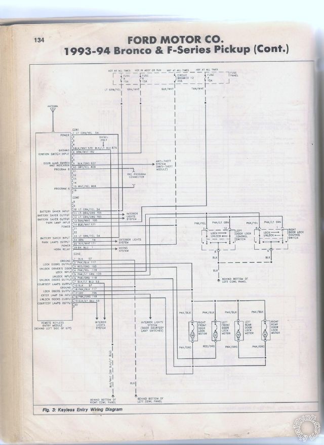
i realize it says 93-94, but compare it to your vehicle
Posted By: Ween
Date Posted: February 03, 2013 at 2:00 PM
so for door lock use pink / YELLOW C242 pin 4, door unlock pink/green C242 pin 5, horn dark blue C240 pin 26...all are negative trigger. for parking lights use brown C240 pin 24, door trigger BLACK/ light blue C242 pin 7 or 19...these are positive polarity.
Posted By: 1966fskbk
Date Posted: February 03, 2013 at 3:41 PM
Your all the freaken BEST! Im going to give it a shot this afternoon.... I do have a nice digital multi-meter as well, this is going to be fun with all your help. Thank you !!!
Mike
-------------
CloudCasters
Posted By: kreg357
Date Posted: February 03, 2013 at 3:54 PM
Hi Mike,
To test for a (-) type wire like Lock or Unlock, set your DMM to 20V DC, connect the Red test lead to +12V constant ( battery ) and the Black test lead to the suspect wire. DMM will indicate +12V when signal is present.
To test for a (+) type wire like Parking Lights, set your DMM to 20V DC and connect the Black test lead to chassis ground and the Red test lead to the suspect wire. DMM will indicate +12V when signal is present.
Have fun with the DMM! 
------------- Soldering is fun!
Posted By: 1966fskbk
Date Posted: February 03, 2013 at 5:17 PM
Here is what I found online and I have the 520.4x:
Responder LE Models
Viper 5204
Clifford 520.4X
Python 524
Security and Remote Start
Installation Guide
Main Harness (H1), 6-pin connector
H1/1 RED (+)12VDC CONSTANT INPUT
H1/2 BLACK (-) CHASSIS GROUND
H1/3 BROWN (+) SIREN OUTPUT
H1/4 WHITE/ BROWN PARKING LIGHT ISOLATION WIRE - PIN 87a of onboard relay
H1/5 WHITE PARKING LIGHT OUTPUT
H1/6 ORANGE (-) 500mA GROUND WHEN ARMED OUTPUT
H2 Harness, 24-pin connector
H2/1 PINK/WHITE (-) 200mA IGNITION/FLEX RELAY CONTROL OUTPUT
H2/2 BLACK/ WHITE (-) NEUTRAL SAFETY INPUT
H2/3 BLUE/WHITE (-) 200mA 2ND STATUS /REAR DEFOGGER OUTPUT
H2/4 GREEN/ BLACK (-) 200mA OEM ALARM DISARM OUTPUT
H2/5 RED / WHITE (-) 200mA TRUNK RELEASE OUTPUT
H2/6 GREEN (-) DOOR TRIGGER INPUT (N/C* OR N/O)
H2/7 BLACK / YELLOW (-) 200mA DOME LIGHT SUPERVISION OUTPUT
H2/8 BROWN / BLACK (-) 200mA HORN HONK OUTPUT
H2/9 DARK BLUE (-) 200mA STATUS OUTPUT
H2/10 PINK (-) 200mA IGNITION 1 OUTPUT
H2/11 WHITE/ BLACK (-) 200mA AUX 3 OUTPUT
H2/12 VIOLET (+) DOOR TRIGGER INPUT
H2/13 WHITE/ VIOLET (-) 200mA AUX 1 OUTPUT
H2/14 VIOLET/BLACK (-) 200mA AUX 2 OUTPUT
H2/15 ORANGE / BLACK (-) 200mA AUX 4 OUTPUT
H2/16 BROWN (+) BRAKE SHUTDOWN INPUT
H2/17 GREY (-) HOOD PIN INPUT (N/C OR N/O)
H2/18 VIOLET / YELLOW (-) 200mA STARTER OUTPUT
H2/19 BLUE (-) TRUNK PIN/ INSTANT TRIGGER INPUT (N/C OR N/O)
H2/20 GREY/BLACK (-) DIESEL WAIT TO START INPUT
H2/21 WHITE/ BLUE (-) REMOTE START/ TURBO TIMER ACTIVATION INPUT
H2/22 ORANGE (-) 200mA ACCESSORY OUTPUT
H2/23 VIOLET/WHITE TACHOMETER INPUT
H2/24 GREEN / WHITE (-) 200mA OEM ALARM ARM OUTPUT
*The Normally Closed setting will only work if one of the vehicle's doors is connected. If more than one door
is to be monitored, then it is recommended to use the Xpresskit DTIMAZDA or tech tip # 1921 on www.directechs.
com to interface with these types of vehicles.
Remote Start, (H3) 10-pin connector
H3/1 PINK (+) IGNITION 1 INPUT/OUTPUT
H3/2 RED / WHITE (87) FLEX RELAY +12V INPUT (30A FUSED)
H3/3 ORANGE (+) ACCESSORY OUTPUT
H3/4 VIOLET (+) STARTER OUTPUT (CAR SIDE OF THE STARTER KILL)
H3/5 GREEN (+) STARTER INPUT (KEY SIDE OF THE STARTER KILL)
H3/6 RED IGNITION 1 +12V INPUT (30A FUSED)
H3/7 PINK/WHITE (30) FLEX RELAY OUTPUT (car side of ign, acc or starter wire)
H3/8 PINK/BLACK (87a) FLEX RELAY INPUT (key side of ign, acc or starter wire if needed)
H3/9 RED / BLACK ACCESSORY/STARTER RELAY +12V INPUT (30A FUSED)
H3/10 NC No Connection
Door Lock, 3-pin connector
1 BLUE (-) 500mA UNLOCK OUTPUT
2 EMPTY NOT USED
3 GREEN (-) 500mA LOCK OUTPUT
-------------
CloudCasters
Posted By: 1966fskbk
Date Posted: February 03, 2013 at 5:20 PM
Here is the unit: Clifford 520.4x
 ------------- CloudCasters
Posted By: 1966fskbk
Date Posted: February 03, 2013 at 5:29 PM
Here is what I think goes where with the help I have received. Please tell me if Im on the right track.
so for door lock use pink / YELLOW C242 pin 4,
(3 PIN - Green)
door unlock pink/green C242 pin 5,
(3 PIN - BLUE)
horn dark blue C240 pin 26...all are negative trigger.
(H2/8 - Brn/Blk)
for parking lights use brown C240 pin 24,
(H1/5 - White)
door trigger BLACK/ light blue C242 pin 7 or 19...these are positive polarity.
(H2/6 - Green)
Am I right?? :)
-------------
CloudCasters
Posted By: 1966fskbk
Date Posted: February 03, 2013 at 5:41 PM
Getting the power:
I think I'm not wanting to grab the constant 12v from steering column. I think I will go the extra and grab dedicated 12v constant from the battery post and run it in through firewall (neatly and in a harness of course). I also was thinking of placing an inline fuse a couple inches from post connection? Good? What size fuse?
Thanks All!!!
-------------
CloudCasters
Posted By: Ween
Date Posted: February 03, 2013 at 6:02 PM
switch your door trigger to H2/12 (purple) as the bronco has positive triggered door switches.
for H1/1 (red), use a 20 amp fuse on 14 gauge wire, the fuse is there to protect the wire.
if you do do remote start functions, it is fine to use the wiring at the ignition switch/steering column.
Posted By: 1966fskbk
Date Posted: February 04, 2013 at 1:49 AM
All wires and testing instructions on how to confirm using a DMM have proven exact. Here are some photos for how its going.
I will spread the gaps on the factory wires a bit more (where the testing tap areas are) and then twist my wires into the spots, solder them then tape them. After completed I will use black 3m wire loom and zip tie shut to hide the attachments.
I will do remote starter part tomorrow. Also mounted siren in motor compartment area pointed down and where it will not get wet.
------------- CloudCasters
Posted By: 1966fskbk
Date Posted: February 04, 2013 at 1:58 AM
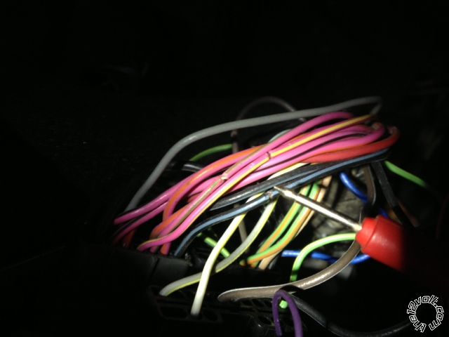
------------- CloudCasters
Posted By: 1966fskbk
Date Posted: February 05, 2013 at 5:33 PM
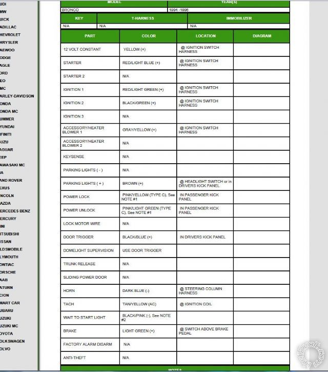
Here is my next "started" plan to connect for Remote Site H3 I am missing some things I think need double checking please:
ALL BOLD next to harness connection - is the 1996 Ford Bronco color I am planning to use, I got this data from the bulldog security diag site - I will post its location next.
Remote Start, (H3) 10-pin connector
H3/1 PINK (+) IGNITION 1 INPUT/OUTPUT Ignition Harness - RED / Light Green (+)
H3/2 RED / WHITE (87) FLEX RELAY +12V INPUT (30A FUSED) not used ?
H3/3 ORANGE (+) ACCESSORY OUTPUT not used
H3/4 VIOLET (+) STARTER OUTPUT (CAR SIDE OF THE STARTER KILL) have no idea ??
H3/5 GREEN (+) STARTER INPUT (KEY SIDE OF THE STARTER KILL) Ignition Harness RED / Light Blue (+)
H3/6 RED IGNITION 1 +12V INPUT (30A FUSED) Ignition Harness RED / Light Green (+)
H3/7 PINK/WHITE (30) FLEX RELAY OUTPUT (car side of ign, acc or starter wire) not used ?
H3/8 PINK/BLACK (87a) FLEX RELAY INPUT (key side of ign, acc or starter wire if needed) not used ?
H3/9 RED / BLACK ACCESSORY/STARTER RELAY +12V INPUT (30A FUSED) not used ?
H3/10 NC No Connection definitely not used :) - GOT THIS ONE RIGHT FOR SURE!!!
Thanks for the help!!!! I think Im in the home stretch.. a
fter I get it all in - when do I get to add the 12v contant and grnd to the unit?
 ------------- CloudCasters
Posted By: Ween
Date Posted: February 05, 2013 at 6:45 PM
H3/1..RED / light green, H3/2..yellow, H3/3..grey / YELLOW, H3/4..RED / light blue(cut this wire connect to vehicle side of wire), H3/5..RED / light blue(ignition switch side of wire), H3/6..yellow, H3/7..BLACK/ light green, H3/8..NC, H3/9..yellow, H3/10..NC. connect each of the red wires(striped or not) to a yellow at the ignition switch. those are all battery power. the green and purple are the in and out for the starter interrupt, which is why the wire is cut(interrupted). all that is left are ignition 1, 2 and accessory.
Posted By: 1966fskbk
Date Posted: February 05, 2013 at 9:56 PM
If I may - this is how I interpret it and I have 1 small question - THANKS WEEN!
H3/1..RED / light green,
H3/2..yellow,
H3/3..grey / YELLOW,
H3/4..RED / light blue(cut this wire connect to vehicle side of wire),
H3/5..RED / light blue(ignition switch side of wire),
H3/6..yellow,
H3/7..BLACK/ light green,
H3/8..NC,
H3/9..yellow,
H3/10..NC.
Step 1:
Connect each of the red wires(striped or not) to a yellow at the ignition switch. Those are all battery power. [B] (Question - can I connect all these all off a direct 10 guage (30 amp fused) run direct from battery post? Or better yet to a small distribution block then all 12v contants from the alarm (red wires) to it? [/B]
Step 2:
The green and purple are the in and out for the starter interrupt, which is why the wire is cut(interrupted).
Step 3:
All that is left are ignition 1, 2 and accessory. ------------- CloudCasters
Posted By: kreg357
Date Posted: February 05, 2013 at 10:37 PM
I would connect the R/S +12V power wires to individual Yellow wires. Keep everything short and inside the vehicle.
Test the ignition wires carefully. There should be 5 Yellow +12V constant wires. You might find something like this.
Ignition1 RED / Light GREEN..........Powers Ignition Coil (Primary Ignition).
Ignition2 GRAY / YELLOW..........Powers ABS Module. 18 Ga
ACC1 BLACK/ Light GREEN........Powers Heat/AC Controls.
ACC2 GRAY / YELLOW (2)......Powers Blower Motor. ** 2 Of The 3 GRAY / YELLOW Wires Listed Are The Same Circuit.
Starter RED / Light Blue
If you need to power an extra ACC circuit, use a 30/40 Amp SPDT relay and wire as follows :
Relay Pin 85 to Viper (-) 200mA Orange Accessory Output
Relay Pin 86 and 87 to +12V constant ( another Yellow wire ) fused at 30 Amps
Relay Pin 30 to ACC2 @ ignition switch harness
Relay Pin 87A not used - insulate ------------- Soldering is fun!
Posted By: Ween
Date Posted: February 05, 2013 at 10:41 PM
a single 30A fuse won't be enough, it would probably blow when a high blower speed is selected. ford shows 2 50A feeds as well as a 20A feed to the ignition switch. one of the 50A feeds supplies the RED / light green and BLACK/ light green, while the other supplies the grey / YELLOW.
the grey / YELLOW is actually two grey / YELLOWs which feeds the blower motor circuit. the 20A feed supplies a third grey / YELLOW (thinner) as well as the RED / light blue. the 50A fuses are numbered 15 and 17, the 20A, 10. i believe the thin grey / YELLOW not listed needs to be powered up. more to follow.
Posted By: Ween
Date Posted: February 05, 2013 at 11:02 PM
thanks kreg for the input...now if it was my vehicle i would revise the H3 connections. H3/1,2,4,5,6 remain the same. H3/3 to thin grey / YELLOW, H3/7 to grey / YELLOW, H3/9 to thin yellow.
a relay would be used for the BLACK/ light green. relay connections, term 30 to yellow (same one powering H3/6), term 87 to BLACK/ light green, term 87a not used, term 86 to thin grey / YELLOW, term 85 to H2/9 (status output). but each installer has their methods for wiring additional relays
Posted By: 1966fskbk
Date Posted: February 06, 2013 at 12:41 PM
Hi All,
So am I reading a relay is required?
And
The color code being refered as BLACK/ light green is actualy BLACK/ green yes? I do not see a BLACK/ light green.
Question:
All cables are soldered that are taped up, I will put everything in a harness when done. I temporaily tied all reds together for testing purposes to one power source, and will tie them in to the Yellows as suggested for sure once everything is confirmed. There is three grey / YELLOWs with one being thinner at ignition. I have tied my orange temporarily to one of the (fat ones) but car won't start. What am I missing ...
Here is my photo. I do hear stuff clicking ... like in the Alarm brain area ... but should I be doing something with the fuse in that little compartment door on the alarm? Program the remotes or something for the start part to work?
Can I hook into the dome light to get it to turn on and off when it unlocks and locks? Do I hook that in as well at the Keyless Entry wireing?
Thanks! (almost there!!)
Oh yeah - doors lock and alarm arms nicely.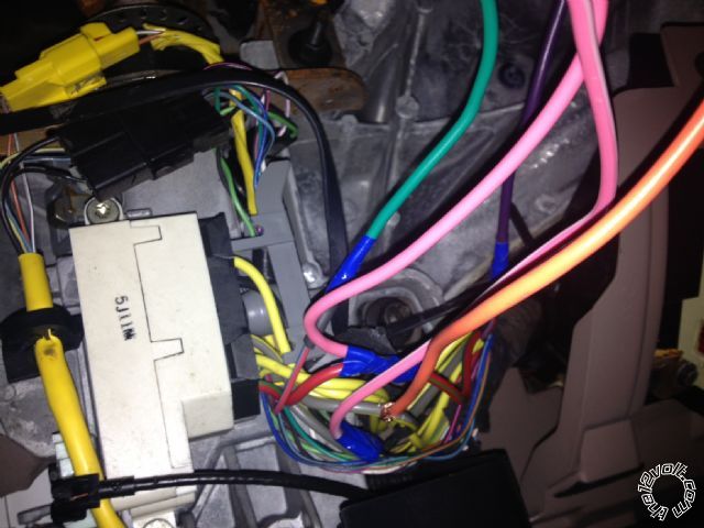
------------- CloudCasters
Posted By: kreg357
Date Posted: February 06, 2013 at 6:13 PM
There are some programming changes necessary for the Viper.
Have you changed to Auto Trans Mode yet?
Have you changed to Tach Mode, connected the Vipers Tach Input wire to a good tach source and done a successful tach learn?
Have you connected the Neutral Safety wire to chassis ground, plugged in the Neutral Safety Switch and turned it to ON?
The jumper/fuse inside the Viper should be set to (+) and the Vipers Parking Light Output wire should be connected to the Bronco's Brown (+) Parking Light wire.
When you do get it to start, gently touch a finger to that lone H3 +12V constant input wire to see how hot it gets ( watch for melting insulation, etc ).  ------------- Soldering is fun!
Posted By: 1966fskbk
Date Posted: February 06, 2013 at 6:33 PM
Holy crud ... no to all the above. hmmm.
Do you guys confirm this setup requrires a relay?
Is Viper the model of Alarm you are refering - Mine is a Clifford - same?
Thanks!
I will go home and put it all in place ...
Thanks!
------------- CloudCasters
Posted By: kreg357
Date Posted: February 06, 2013 at 7:27 PM
Yes, current Viper, Clifford are all similar Directed products.
As for the extra relay to power all the ignition circuits... The jury is out on that one.
While it is not always absolutely necessary to power all the ignition wires for a successful remote start, depending on the vehicle, strange things can happen if you don't. It could be something simple like the heat AC fans don't come on or the power windows don't work while under remote start. It can be more serious with ABS or Engine Check Lights. Some GM vehicles can incur transmission damage if the White Ignition2 wire is not powered. Anyway some installers like to save time / money by powering the bare minimum circuits. Other do it that way because they don't want the radio on or the wipers to come on during remote start. Some figure it's safer to install it to work exactly like a normal key start would and power everything.
Bottom line, the choice is yours. As Ween noted, all these circuits are high current draw circuits, so you don't want to try to use one Clifford output wire to power two vehicle circuits ( hence the relay ). ------------- Soldering is fun!
Posted By: 1966fskbk
Date Posted: February 08, 2013 at 2:56 PM
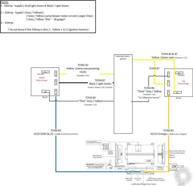
So here are the two relay designs. I do not understand why they are so different - thanks for the help understanding why one or the other...
Clearly:
One is using a STATUS output (alarm side)?
One is using the Thick vs Thin Grey / Yellow?
One is tyine 2 terminals to a single Yellow?
One is getting power from the BLACK/ Light Green?
One is using the ACC output (alarm side)?
------------- CloudCasters
Posted By: kreg357
Date Posted: February 08, 2013 at 3:42 PM
Ok, have some confusion going on. Obviously, you want to test all these wires with a DMM prior to making
the actual connections. The below chart is made ASSUMING that the Ready Remote info for your 1996 Bronco
is accurate. (Please note that there are many ways to wire up the extra relay to provide an extra high current
Accessory output for the Bronco's ignition harness. Every installer has their own favorite way to do it.)
Remote Start, (H3) 10-pin connector
H3/1 PINK (+) IGNITION 1 RED / Light Green (+) @ Bronco ignition switch harness
H3/2 RED / WHITE +12V INPUT (30A FUSED) Yellow #1 @ Bronco ignition switch harness
H3/3 ORANGE (+) ACCESSORY OUTPUT Gray / YELLOW ( thick ) @ Bronco ignition switch harness
H3/4 VIOLET (+) STARTER OUTPUT (CAR SIDE ) RED / Light Blue (+) @ Bronco ignition switch harness cut wire car side
H3/5 GREEN (+) STARTER INPUT (KEY SIDE) RED / Light Blue (+) @ Bronco ignition switch harness cut wire ignition switch side
H3/6 RED IGNITION 1 +12V INPUT (30A FUSED) Yellow #2 @ Bronco ignition switch harness
H3/7 PINK/WHITE (30) FLEX RELAY OUTPUT Gray / YELLOW ( thin ) @ Bronco ignition switch harness
H3/8 PINK/BLACK (87a) FLEX RELAY INPUT not used
H3/9 RED / BLACK ACC/STARTER RELAY +12V Yellow #3 @ Bronco ignition switch harness
H3/10 NC
Extra 30/40 Amp SPDT Relay
Relay Pin 85 to Clifford 520.4X H2/22 Orange (-) 200 mA Accessory Output
Relay Pin 86 and 87 to Bronco ignition switch harness Yellow #4 thru 30 Amp fuse
Relay Pin 30 to Bronco ignition switch harness BLACK/ Green
Relay Pin 87a not used - insulate
All Yellow's should test as +12V constant. You can connect the Clifford 520.4X H1 Red +12V constant input wire to Yellow #5.
With the above relay wiring, the relay coil is energized whenever the Clifford H2/22 Accessory output goes True ( negative ). The
relays coil has constant power on Pin 86 supplied by the Yellow ignition +12V constant wire. This same Yellow wire also provides
fused +12V constant power to relay Pin 87. Relay Pin 30 will make contact with relay Pin 87 when the relays' coil is energized. With this
setup, everything remains isolated and is solely controlled by the Clifford R/S. Additionally, I would recommend a 1N4007 diode
across relay Pins 85 to 86, with the diodes' band towards Pin 86. ------------- Soldering is fun!
Posted By: 1966fskbk
Date Posted: February 08, 2013 at 6:03 PM
OK this may be hard to see but I think I have it!
Thanks - please double check.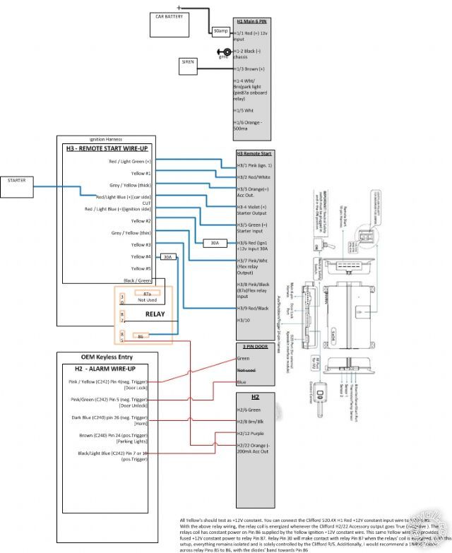 ------------- CloudCasters
Posted By: kreg357
Date Posted: February 08, 2013 at 7:09 PM
A few minor things...
Clifford H3/2 RED / White should have a 30 Amp fuse in the wire ( not shown in diagram ).
Clifford H3/7 Pink/White should be OK with the factory default programming = IGN2
Not included on the diagram is the extra ACC2 relay coil quenching diode.
I'm guessing that the Clifford H1/5 White Parking Light is connected to the Bronco and working OK.
There are a few more wires not listed / shown that are important for the remote start portion of the install.
H2/2 BLACK/ WHITE (-) NEUTRAL SAFETY INPUT to Chassis Ground ** also install Neutral Safety Switch & set to ON
H2/16 BROWN (+) BRAKE SHUTD0WN INPUT to Brake Wire Light Green (+) @ brake pedal switch
H2/17 GREY (-) H00D PIN INPUT (N/C 0R N/0) to hood pin supplied in Clifford kit
H2/23 VIOLET/WHITE TACHOMETER INPUT Tachometer Tan / YELLOW (AC) @ at coil ** Set Clifford to Engine Checking = Tach ------------- Soldering is fun!
Posted By: 1966fskbk
Date Posted: February 08, 2013 at 8:05 PM
I do not know where Im going ... but Im on my way!!!
I will update and repost... thanks so much folks!!!
I plan on finalizing / finishing everything this weekend...
Mike ------------- CloudCasters
Posted By: 1966fskbk
Date Posted: February 08, 2013 at 11:12 PM
OK - the only thing I think Im missing is how to turn on the dome light? I take it that this wire turns on dome? Do I want to turn on dome?
H2/7 BLACK / YELLOW (-) 200mA DOME LIGHT SUPERVISION OUTPUT (One source I seen says connect to door trigger?) (Is door trigger pos.Trigger and wont that not work?)
------------- CloudCasters
Posted By: kreg357
Date Posted: February 09, 2013 at 6:21 AM
Dome Light Supervision is optional. It is a nice feature but may not be necessary if the Cliffords'
Unlock command not only unlocks the doors but causes the dome light to turn on. Most newer
vehicles have this built in. Test to see if this happens.
Your Clifford unit outputs a (-) Dome Light Supervision signal. The Bronco uses a (+) signal from the
door pin to indicate an open door ( an open door causes the Bronco to turn on the Dome Light ). You
would need a relay to convert the Cliffords' (-) output to be acceptable / usable by the Bronco. A 30/40
Amp SPDT relay would be used for this conversion and wired as below :
Relay Pin 85 to Clifford H2/7 BLACK / YELLOW (-) 200mA DOME LIGHT SUPERVISION OUTPUT
Relay Pin 86 and 87 to Bronco Yellow #5 +12V constant fused at 10 Amps
Relay Pin 30 to Bronco All Door Trigger BLACK/ LIGHT BLUE (+) @ DRIVER'S KICK PANEL
Relay Pin 87a not used - insulate ( or de-pin ) ------------- Soldering is fun!
Posted By: 1966fskbk
Date Posted: February 10, 2013 at 2:55 PM
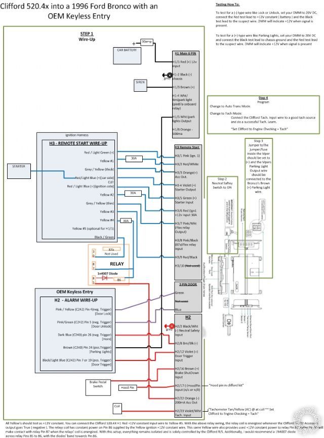
So this is fantastic!!! Everything worked first time!!! - Of course after setting feature 3 to "auto transmission" and putting in fuse located on the alarm brain, to correct + setting for lights.. oh yeah then doing tach learn.
A BIG Thanks to the12volt.com FORUM!! - this was a great learning experience, I have my entire wiring schematic above, know every connection is soldered taped and fused perfectly. I hope that the documentation in this thread will help anyone else needing to Clifford 520.4x installed. Big thanks to kreg357 and WEEN!
My Install Notes: Everything is harnessed (black wire loom), I even used the factory firewall plug housing (pins that were vacant) to run the hood/pin, siren & tach through wires into the motor compartment area. I also made an insulated quick disconnect connector for the tach to alarm...in case the two need to separate in the future for motor repairs.
Last Question: I would love to now have the AUX button on my remote roll down the vehicles back window (only)for grocerie getting ease. How would I be able to do that
-------------
CloudCasters
Posted By: Ween
Date Posted: February 10, 2013 at 3:37 PM
you'll need to locate the wire at the rear window switch that has power when the switch is pressed to the down position. did the same for my neighbor's bronco, can't remember the colors though. once you find the wire, you'll cut it to interrupt. wire as follows to additional relay:
term 87 and 86 ...battery power (fuse at same rating as rear window from factory...20A?)
term 87a ...down wire (switch side)
term 30 ...down wire (vehicle side)
term 85 ...aux output from remote starter (negative control)\
Posted By: kreg357
Date Posted: February 10, 2013 at 5:04 PM
Using a Clifford AUX output to roll down the back window might require a BitWriter to set the AUX
output duration to a fixed time period. Measure the the number of seconds that it takes to roll down
the window and add 1 second, then use the BitWriter to program that time for the AUX output.
Another way is like Ween's also but uses a Directed 528T module, which has a 15 Amp relay built in
and can be set for any output duration from 1 to 90 seconds. If you want up and down check
out the Directed 529T module. ------------- Soldering is fun!
Posted By: 1966fskbk
Date Posted: February 10, 2013 at 5:48 PM
how do i get a bitwriter or is it an app on my PC?
thanks ------------- CloudCasters
Posted By: kreg357
Date Posted: February 10, 2013 at 6:08 PM
It is an actual hand held device that connects to and communicates with the Directed control module ( brain ).
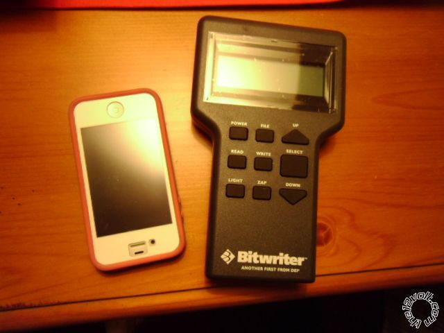
They go for about $70 but make setting options a breeze and allow setting the BitWriter only options listed at the end of the option tables.
Do a search on BitWriter 998t. Look for one with the latest version Prom Chip ( Ver 2.7 is OK, Ver 2.9 is the latest ).
The Directed 528T is only $13 and includes the relay.. ------------- Soldering is fun!
Posted By: 1966fskbk
Date Posted: February 11, 2013 at 5:23 PM
what is the diff in the
Directed 528T is only $13 and includes the relay..
and Bitwriter?
Found this at SEARS of all places ...
Directed Electronics Directed Electronics 998U The Bitwriter (Upgrade Chip Version)
Is it the same as well.
Thanks! ------------- CloudCasters
Posted By: Ween
Date Posted: February 11, 2013 at 5:51 PM
the 528T is a universal timer module, whereas the bitwriter is a programmer that allows one to change the settings in the menus. gives you a wider access to the options that the menus offer as compared to using the programming button for accessing those options. some options can only be changed using the bitwriter. see pages 12 - 19 of the installation manual.
Posted By: kreg357
Date Posted: February 11, 2013 at 6:38 PM
Haven't tried it on a Clifford, but the AUX1 default is Validity, which means the the AUX1 output will
continue for as long as the button is pressed. That could mean it is possible with just the relay setup
Ween posted. You would just hold the AUX1 button until the window was all the way down.
The BitWriter 998U upgrade chip might only be the prom chip ( Ver 2.7 or Ver 2.9 ), not the entire 998T
BitWriter programmer.
Without the BitWriter, the closest you can get ( if Validity didn't work ) with using the remotes to program
the Clifford is a 30 Second AUX output, which would be like holding the window down switch for a full 30
seconds. Not sure how the Bronco would handle that.
Here is a link to the DEI 528T module install info : https://www.the12volt.com/installbay/file.asp?ID=457 ------------- Soldering is fun!
Posted By: 1966fskbk
Date Posted: November 06, 2013 at 12:22 PM
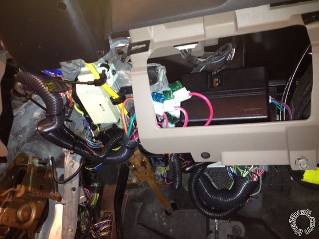
Here is where I located the alarm and its all harnessed. The sensor was located high above the rear view mirror stuck to the windshield like it is designed to be. It is so the signal for the remote is at optimum and the LED can be seen glowing through all the windows. Excellent product.
 ------------- CloudCasters
|