viper 5902 + dball in hyundai 2012
Printed From: the12volt.com
Forum Name: Car Security and Convenience
Forum Discription: Car Alarms, Keyless Entries, Remote Starters, Immobilizer Bypasses, Sensors, Door Locks, Window Modules, Heated Mirrors, Heated Seats, etc.
URL: https://www.the12volt.com/installbay/forum_posts.asp?tid=133646
Printed Date: May 16, 2026 at 3:24 AM
Topic: viper 5902 + dball in hyundai 2012
Posted By: tameros
Subject: viper 5902 + dball in hyundai 2012
Date Posted: February 20, 2013 at 4:21 PM
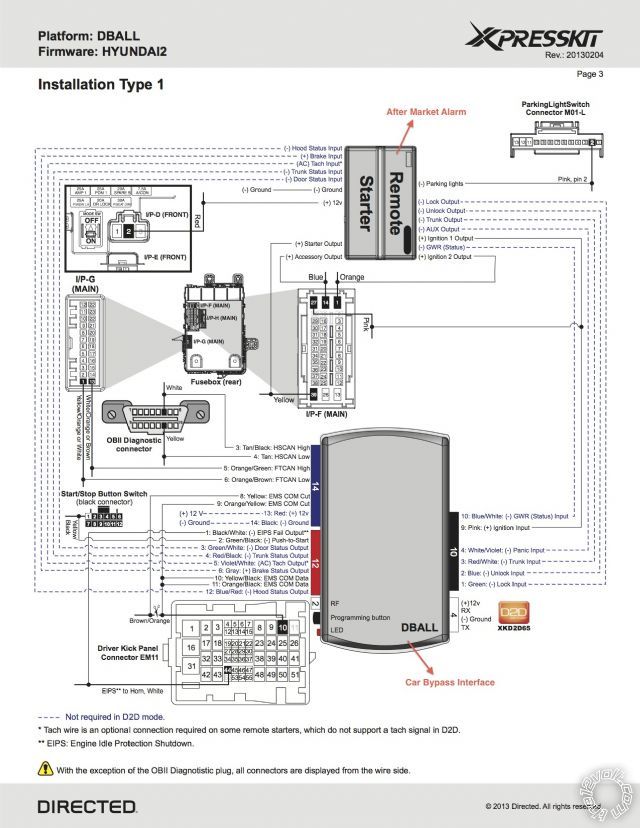
Will the DBALL when connected to Viper 5902 as in the attached image, remote start the car, Arm & Disarm OEM alarm and Open the Trunk? Viper trigger if door or hood opened without any further connection to Viper's CPU
Replies:
Posted By: tameros
Date Posted: February 21, 2013 at 8:05 AM
Do i need to connect any relays or diodes in this connection?
Posted By: offroadzj
Date Posted: February 21, 2013 at 10:52 AM
First word of advice, don't use D2D. Take the time at the workbench and make all of the physical connections between the bypass and the remote start / alarm (W2W). Basically make all of the connections shown regardless of solid vs dotted lines. With that, the bypass should supply the door status, trunk status, and hood status (if the vehicle is equipped with a factory hood pin). Not all vehicles have a factory hood pin so you may need to add the hood pin that is included with the remote start.
-------------
Kenny
Owner / Technician
KKD Garage LLC
Albany, NY 12205
Posted By: tameros
Date Posted: February 22, 2013 at 6:31 PM
Why shouldn't i use the D2D?
Is there a concern beside being able to show the hood status and so?
Posted By: offroadzj
Date Posted: February 22, 2013 at 9:05 PM
D2D is very unreliable and does not give you the ability to test anything when an issue arises. It takes only a few minutes during the bench prep to connect the wires between the unit and bypass but it could save you hours of hassle down the road.
-------------
Kenny
Owner / Technician
KKD Garage LLC
Albany, NY 12205
Posted By: howie ll
Date Posted: February 23, 2013 at 12:51 AM
Tamar, you see the point I made about D2D?
Also Kenny has more experience with this vehicle.
-------------
Amateurs assume, don't test and have problems; pros test first. I am not a free install service.
Read the installation manual, do a search here or online for your vehicle wiring before posting.
Posted By: tameros
Date Posted: February 23, 2013 at 4:32 AM
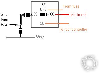
Ok so can we revise the connections please
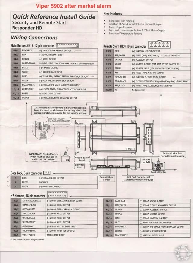 DBALL Viper 5902
Blue Harn. Pin 13 +12V Red to same +12V on I/P-D Pin 2 in smart junction box
Blue Harn. Pin 14 - ground to chasis or connect with ground of Viper 5902 H1/5 Black
Red Harn. Pin 3 GREEN / WHITE to 5902 CPU H1/8 Green (-) Door Trigger Input
Red Harn. Pin 4 RED / Black to 5902 CPU H1/7 Blue (-)Trunk Pin/Instant Trigger Input
Red Harn. Pin 5 Violet/White to 5902 CPU H2/9 Violet/White Tachometer Input
Red Harn. Pin 6 Grey to 5902 CPU H2/17 Brown (+) Brake Shutdown Input
Red Harn. Pin 12 Blue/Red to 5902 CPU H2/15 Grey (-) Hood Pin Input
Black Harn. Pin 1 Green to 5902 CPU Door Lock Harn. Pin 3 Green (-) 500mA Lock Output
Black Harn. Pin 2 Blue to 5902 CPU Door Lock Harn. Pin 1 Blue (-) 500mA Unlock Output
Black Harn. Pin 3 RED / White to 5902 CPU H1/1 RED / White (-) 200mA Trunk Release Output
Black Harn. Pin 4 WHITE/ Violet to 5902 CPU ?????? (I don't know to which wire)
Black Harn. Pin 10 Blue/White to 5902 CPU ?????? (I don't Know what is GWR and to which wire)
Black Harn. Pin 9 Pink Soldered to 5902 CPU H3/1 Pink (+) Ignition 1 Input/Output so
cable will be soldered I/P-F Pin 27 in smart junction box
For this wire connection will I need any diodes or relays or fuse?
Posted By: howie ll
Date Posted: February 23, 2013 at 4:54 AM
Black Pin 4 WHITE/ violet to 5902 H2/6 aux1
Pin 10 Blue/white to 5902 H2/10 dark blue OR H2/16 Blue/white.
Status output, also known as GWR (ground whilst running) puts out about 200mA to ground when the R/S is engaged. Think of it as an extra NEG (-) ignition output.
-------------
Amateurs assume, don't test and have problems; pros test first. I am not a free install service.
Read the installation manual, do a search here or online for your vehicle wiring before posting.
Posted By: tameros
Date Posted: February 23, 2013 at 7:09 AM
All my other connections are right like that, and do i need any kind of protection for the car or viper or dball installed?
Posted By: tameros
Date Posted: February 23, 2013 at 7:12 AM
Hi Kenny
As you know the vehicle well do i need to make any protection of diodes to my car OEM wiring in order not to damage anything?
Posted By: howie ll
Date Posted: February 23, 2013 at 7:35 AM
No, it's all low current.
-------------
Amateurs assume, don't test and have problems; pros test first. I am not a free install service.
Read the installation manual, do a search here or online for your vehicle wiring before posting.
Posted By: offroadzj
Date Posted: February 23, 2013 at 9:41 AM
As far as I know, there are no diodes needed.
-------------
Kenny
Owner / Technician
KKD Garage LLC
Albany, NY 12205
Posted By: howie ll
Date Posted: February 23, 2013 at 9:50 AM
You have 2 reds, a RED / black, and a RED / white. Power (connect) them all to a constant source but you should only need about 15 amps for ALL because you are switching data through the DB-ALL rather than power.
-------------
Amateurs assume, don't test and have problems; pros test first. I am not a free install service.
Read the installation manual, do a search here or online for your vehicle wiring before posting.
Posted By: tameros
Date Posted: February 23, 2013 at 6:06 PM
I want to check this point is
Black Harn. Pin 1 Green --> 5902 CPU Door Lock Harn. Pin 3 Green (-) 500mA Lock Output
Black Harn. Pin 2 Blue --> 5902 CPU Door Lock Harn. Pin 1 Blue (-) 500mA Unlock Output
Those two are right?
As for your previous post about
Black Pin 4 WHITE/ violet --> 5902 H2/6 aux1
Black Pin 10 Blue/white --> 5902 H2/10 dark blue
Do I need to program anything in my Viper 5902 for those two connections
Posted By: howie ll
Date Posted: February 23, 2013 at 11:52 PM
Correct and no.
-------------
Amateurs assume, don't test and have problems; pros test first. I am not a free install service.
Read the installation manual, do a search here or online for your vehicle wiring before posting.
Posted By: tameros
Date Posted: February 24, 2013 at 12:15 AM
What you mean by correct and no, pls explain
Posted By: howie ll
Date Posted: February 24, 2013 at 1:00 AM
Black Harn. Pin 1 Green --> 5902 CPU Door Lock Harn. Pin 3 Green (-) 500mA Lock Output
Black Harn. Pin 2 Blue --> 5902 CPU Door Lock Harn. Pin 1 Blue (-) 500mA Unlock Output
Those two are right?
Black Pin 4 WHITE/ violet --> 5902 H2/6 aux1
Black Pin 10 Blue/white --> 5902 H2/10 dark blue
Above statements are correct.
Do I need to program anything in my Viper 5902 for those two connections
NO.
-------------
Amateurs assume, don't test and have problems; pros test first. I am not a free install service.
Read the installation manual, do a search here or online for your vehicle wiring before posting.
Posted By: howie ll
Date Posted: February 24, 2013 at 1:02 AM
Wire exactly as the first diagram you posted.
-------------
Amateurs assume, don't test and have problems; pros test first. I am not a free install service.
Read the installation manual, do a search here or online for your vehicle wiring before posting.
Posted By: tameros
Date Posted: February 24, 2013 at 2:13 AM
You mean i should remove all the dashed connection again ?
Howard it is now very confusing could you please make it more easier for me
Posted By: howie ll
Date Posted: February 24, 2013 at 2:34 AM
No, use the dashed connections.
-------------
Amateurs assume, don't test and have problems; pros test first. I am not a free install service.
Read the installation manual, do a search here or online for your vehicle wiring before posting.
Posted By: tameros
Date Posted: February 27, 2013 at 6:50 AM
Howard
on your Post: 23 February 2013 at 11:50 AM
You wrote "You have 2 reds, a RED / black, and a RED / white. Power (connect) them all to a constant source but you should only need about 15 amps for ALL because you are switching data through the DB-ALL rather than power."
You mean the 2 reds (RED / black + RED / white) on DBALL?
isn't the RED / Black (-)TRUNK STATUS OUTPUT on DBALL supposed to connect to H1/7 Blue on Viper [(-) TRUNK PIN / INSTANT TRIGGER INPUT].
and isn't the RED / White (-) TRUNK INPUT on DBALL supposed to connect to H1/1 RED / White on Viper [(-) 200 mA TRUNK RELEASE OUTPUT].
SO why should I connect them to constant +12V power and put them a fuse 15A, aren't both 2 different signals, I am sure I miss understood the post somehow.
Can you please clarify I got really confused, as I am preparing all connections now and label them for the installation.
Then later i have some question about some settings on Viper and a couple of connections that still are not clear and trying to search
Posted By: tameros
Date Posted: February 27, 2013 at 6:51 AM
I am sorry it is taking a longtime to install because I am trying to be accurate and because I can only work on this after I am back home from work.
So pls be patient with me.
Thanks
Posted By: howie ll
Date Posted: February 27, 2013 at 7:12 AM
No I meant on the R/S unit only the red to 12V+ and the black to ground on the DB-ALL follow the W2W diagram you showed.
-------------
Amateurs assume, don't test and have problems; pros test first. I am not a free install service.
Read the installation manual, do a search here or online for your vehicle wiring before posting.
Posted By: howie ll
Date Posted: February 27, 2013 at 7:14 AM
13 red and 14 black, blue plug on the DB-ALL
-------------
Amateurs assume, don't test and have problems; pros test first. I am not a free install service.
Read the installation manual, do a search here or online for your vehicle wiring before posting.
Posted By: tameros
Date Posted: February 27, 2013 at 11:23 AM
Yes the red wires from R/S unit and the DBALL to +12V Constant, the 2 black ground wires on R/S unit and DBALL to car chassis
Some other question
For the violet/white on the red DBALL connector it states (AC) Tach output, on the R?S Unit H2/9 violet/white Tachometer input. Does it handle the AC from the DBALL unit?
Can i leave the D2D connection connected between the R/S unit and DBALL unit in addition to W2W connection or must i remove it.
Is the connection of Panic input on DBALL from H2/6 Aux 1 output necessary if my car has no panic button on the OEM remote.
Posted By: howie ll
Date Posted: February 27, 2013 at 11:42 AM
For the violet/white on the red DBALL connector it states (AC) Tach output, on the R?S Unit H2/9 violet/white Tachometer input. Does it handle the AC from the DBALL unit?
Yes. Connect one to the other. This is the good thing about wiring D2D. If it doesn't work, you can still hard wire from H2/9 it to a tach feed in the car
Can i leave the D2D connection connected between the R/S unit and DBALL unit in addition to W2W connection or must i remove it.
No, remove it.
Is the connection of Panic input on DBALL from H2/6 Aux 1 output necessary if my car has no panic button on the OEM remote.
Don't bother with it.
-------------
Amateurs assume, don't test and have problems; pros test first. I am not a free install service.
Read the installation manual, do a search here or online for your vehicle wiring before posting.
Posted By: tameros
Date Posted: February 27, 2013 at 11:50 AM
The following cables on the R/S unit i don't need right any future connection on my car?
H1/4 WHITE/ Brown Parking light isolation wire - pin 87a of on board relay
H1/10 WHITE/ Blue (-) Remort start / Turbotimer activation input (not needed right)
H2/7 Grey/Black (-) Diesel wait to start input (as my car is not diesel)
H2/11 Pink/White (-) 200 mA flex relay control output
H2/12 Orange (-) 200 mA Accessory output
H2/13 Purple (-) 200 mA Starter output
H2/14 Pink (-) 200 mA Ignition 1 output
H2/16 BLACK/ White (-) Neutral safety input (as my car is automatic)
H3/2 RED / White (+) Fused (30A) Ignition 2 / Flex relay Input 87
H3/5 Green (+) Starter input (key side of starter kill)
H3/6 Red (+) Fused (30A) Ignition 1 Input
H3/8 Pink/Black (+) flex relay input 87a key side (if required) of flex relay
H3/9 RED / Black (+) Fused (30A) Accessory / starter input
I think DBALL already is alternative for those connection on the R/S unit, so don't need them to right?
H1/6 Violet (+) Door Trigger input
H1/9 BLACK/ White (-) 200 mA Dome light supervision output
H2/1 Light GREEN/ Black (-) 200 mA OEM Alarm disarm output
H2/3 GREEN / WHITE (-) 200 mA OEM Alarm arm output
H2/8 BROWN / Black (-) 200 mA horn honk output
Those i need still ready the R/S unit, right?
H1/3 Brown (+) Siren output (Will need it to trigger the sirens)
H1/12 Orange (-) 500 mA ground when armed (Will need to arm the sensors)
H2/2 ORANGE / Black (-)200mA Aux 4 Output + H2/4 Violet/Black (-)200mA Aux 2 Output + H2/5 WHITE/ Black (-)200mA Aux 3 Output (As i will need them if i want to install window modules or any other accessories that are controlled by the R/S unit remote), also the same for H2/6 WHITE/ Violet (-)200mA Aux 1 Output if I don't need the DBALL panic wire anymore
H2/16 Blue/White (-) 200 mA 2nd Status / Rear defogger output (to operate the rear windshield defogger of the car if i want to through a latched relay control (On/off)
Posted By: tameros
Date Posted: February 27, 2013 at 11:54 AM
If i remove the D2D wire i will loose the following options
FOB-Control of after market alarm with OEM remote
+
SS-Entry monitoring of driver door pin
So is it a must to remove D2D wire or can i leave it connected too
Posted By: tameros
Date Posted: February 27, 2013 at 11:55 AM
Sorry i am asking to much but i am installing the system tomorrow after noon and continue after tomorrow.
Only the DBALL and R/S unit.
The Sirens and other sirens plus the sensors the week after
Posted By: howie ll
Date Posted: February 27, 2013 at 11:59 AM
H2/12 Orange (-) 200 mA Accessory output
H2/13 Purple (-) 200 mA Starter output
H2/14 Pink (-) 200 mA Ignition 1 output Any of these loom away and insulate, future use?
H2/16 BLACK/ White (-) Neutral safety input (as my car is automatic) Must connect to ground or DB-ALL (refer to your diagram).
H3/2 RED / White (+) Fused (30A) Ignition 2 / Flex relay Input 87 MUST CONNECT
H3/6 Red (+) Fused (30A) Ignition 1 Input Ditto
H3/9 RED / Black (+) Fused (30A) Accessory / starter input Ditto
-------------
Amateurs assume, don't test and have problems; pros test first. I am not a free install service.
Read the installation manual, do a search here or online for your vehicle wiring before posting.
Posted By: howie ll
Date Posted: February 27, 2013 at 12:03 PM
Do NOT connect it in D2D as well, it won't work.
I don't know the answer but why do YOU think you will lose these functions?
-------------
Amateurs assume, don't test and have problems; pros test first. I am not a free install service.
Read the installation manual, do a search here or online for your vehicle wiring before posting.
Posted By: tameros
Date Posted: February 27, 2013 at 12:04 PM
"H2/16 BLACK/ White (-) Neutral safety input (as my car is automatic) Must connect to ground or DB-ALL (refer to your diagram)."
isn't the neutral on/off switch supplied enough when left on 
"H3/6 Red (+) Fused (30A) Ignition 1 Input Ditto
H3/9 RED / Black (+) Fused (30A) Accessory / starter input Ditto"
what does ditto mean, don't know what to do with them
Posted By: tameros
Date Posted: February 27, 2013 at 12:08 PM
"I don't know the answer but why do YOU think you will lose these functions?"
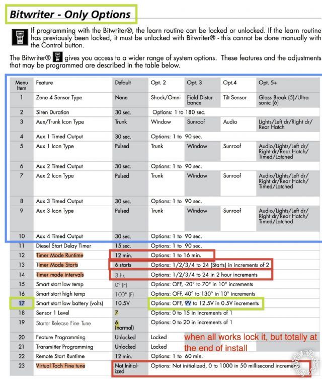
Because of this page in the DBALL installation guide page
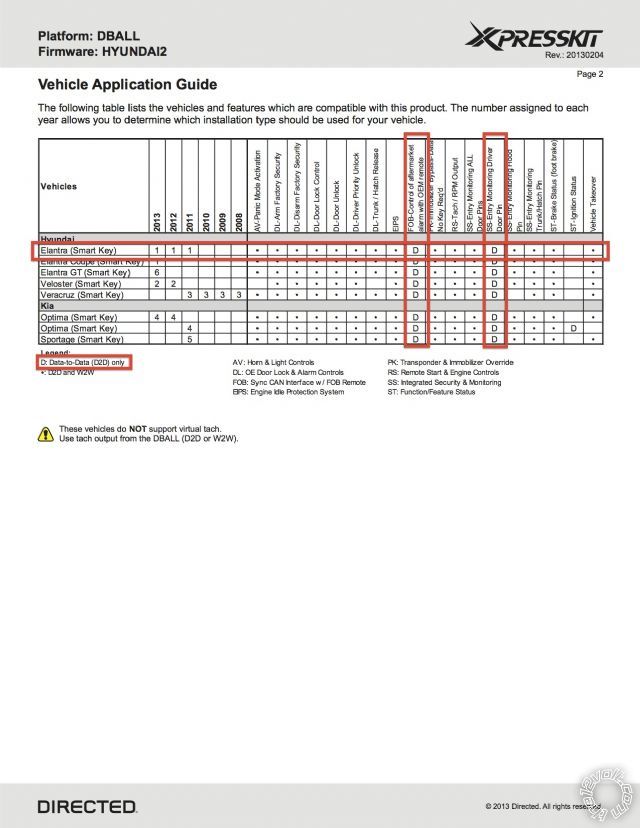
Posted By: tameros
Date Posted: February 27, 2013 at 12:12 PM
And as i will set the following features on the DBALL
as highlighted in yellow
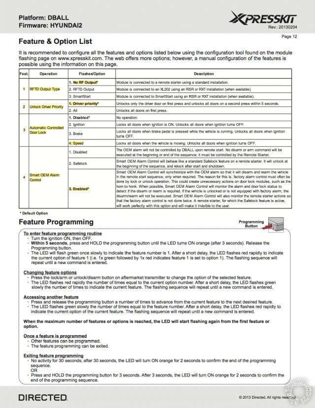
Posted By: tameros
Date Posted: February 27, 2013 at 12:35 PM
so Howard what do you think?
Posted By: offroadzj
Date Posted: February 27, 2013 at 1:34 PM
The black / white must still be connected to ground. The switch is more of a safety switch so the remote start feature can be turned off if needed (ie working on vehicle).
The Red and Red / Black wires must connect to 12volt constant along with the Red / White.
-------------
Kenny
Owner / Technician
KKD Garage LLC
Albany, NY 12205
Posted By: tameros
Date Posted: February 27, 2013 at 2:10 PM
"The black / white must still be connected to ground. The switch is more of a safety switch so the remote start feature can be turned off if needed (ie working on vehicle)."
OK so can i solder it with [H1/5 Black ground of the R/S unit] together with the [14 Black (-) ground on the DBALL (Blue 14 Pin Socket)]
"The Red and Red / Black wires must connect to 12volt constant along with the Red / White."
I will connect the [H1/2 Red + 12VDC constant (15A) Fused] with the [13 Red (+) 12 V on DBALL (Blue 14 Pin Socket)] both before the fuse nearer to the R/S unit
I will connect the [H3/2 RED / White (+) Fused (30A)] Together with the [H3/9 RED / Black (+) Fused (30A)] to constant +12 VDC constant both with one 30A fuse protecting them
OK like that?
Posted By: howie ll
Date Posted: February 27, 2013 at 2:16 PM
Yes but if you aren't using the switch and most people don't looks ugly on a modern car, plug it in to the unit, cut off the switch and join those two leads together.
-------------
Amateurs assume, don't test and have problems; pros test first. I am not a free install service.
Read the installation manual, do a search here or online for your vehicle wiring before posting.
Posted By: tameros
Date Posted: February 27, 2013 at 2:31 PM
OK will loom those away and insulate
H2/12 Orange (-) 200 mA Accessory output
H2/13 Purple (-) 200 mA Starter output
H2/14 Pink (-) 200 mA Ignition 1 output
What about those what should i do with them and do i need them?
H1/4 WHITE/ Brown Parking light isolation wire - pin 87a of on board relay
H1/10 WHITE/ Blue (-) Remort start / Turbotimer activation input (not needed right)
H2/7 Grey/Black (-) Diesel wait to start input (as my car is not diesel)
H2/11 Pink/White (-) 200 mA flex relay control output
And what about those?
H3/5 Green (+) Starter input (key side of starter kill)
H3/8 Pink/Black (+) flex relay input 87a key side (if required) of flex relay
Should i connect this [H3/6 Red (+) Fused (30A) Ignition 1 Input] to the group i mentioned below too? [H3/2 RED / White] [H3/9 RED / Black] to constant +12 VDC constant all with one 30A fuse protecting them
Posted By: howie ll
Date Posted: February 27, 2013 at 2:37 PM
The answer to all of the questions in the above post is YES.
-------------
Amateurs assume, don't test and have problems; pros test first. I am not a free install service.
Read the installation manual, do a search here or online for your vehicle wiring before posting.
Posted By: tameros
Date Posted: February 27, 2013 at 3:19 PM
What you mean YES for those. Loom all the below ??????????
H1/4 WHITE/ Brown Parking light isolation wire - pin 87a of on board relay
H1/10 WHITE/ Blue (-) Remort start / Turbotimer activation input (not needed right)
H2/7 Grey/Black (-) Diesel wait to start input (as my car is not diesel)
H2/11 Pink/White (-) 200 mA flex relay control output
H3/5 Green (+) Starter input (key side of starter kill)
H3/8 Pink/Black (+) flex relay input 87a key side (if required) of flex relay
Posted By: howie ll
Date Posted: February 27, 2013 at 6:12 PM
Yes. If they aren't on that DB-ALL diagram, then don't use them.
-------------
Amateurs assume, don't test and have problems; pros test first. I am not a free install service.
Read the installation manual, do a search here or online for your vehicle wiring before posting.
Posted By: tameros
Date Posted: February 27, 2013 at 6:18 PM
OK thanks Howard
Posted By: tameros
Date Posted: February 27, 2013 at 6:26 PM
Can you tell what you think about the viper settings i marked in the following pictures
The features framed in green are the ones i want to change
The features highlighted in red I don't know what to set them
The features i framed in blue is another phase will work in next week
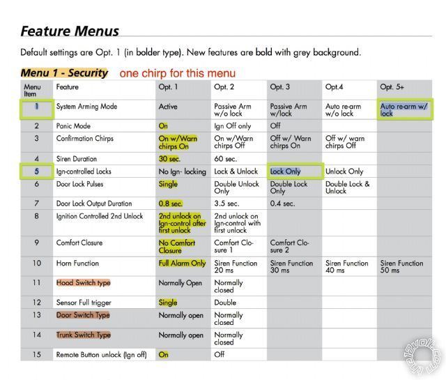
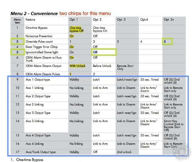
The features to be programmed with bitwriter
Posted By: howie ll
Date Posted: February 27, 2013 at 6:55 PM
Menu 1/1 Don't even think about doing this the day you leave your keys in the car at 2:00 am in the desert are when you will want to kill yourself. And please don't give me that rubbish about "I never leave my keys in the car".
Menu 1/5 Make that lock and unlock,otherwise it will drive you mad, more so your passengers unless you're a taxi driver.
Menu 1/ 11, 13 and 14 leave in default.
The rest are correct.
Menu 2 All OK except 5 leave in default.
Menu 3/1 If its an auto then select automatic.
Menu 3/2 Tachometer
Menu 3/3 Cranking. Leave in default if it turns over but doesn't start, then extend.
Menu 3/8 Ignore
Menu 3/10 OFF.
Menu 3/11 Ignore
Menu 4/12 The longer the better.
Menu 4/13 4
Menu 4/14 Leave in default.
Menu 4 /17 12V
Menu 4/20 and 21 up to you.
Menu 4/23 Leave in default.
You do realise that you're messing around with this one install more than the average installer will do in a year!
And boy is this going to give you problems. If it works and it ain't broke, DON'T TOUCH.
-------------
Amateurs assume, don't test and have problems; pros test first. I am not a free install service.
Read the installation manual, do a search here or online for your vehicle wiring before posting.
Posted By: tameros
Date Posted: February 27, 2013 at 7:11 PM
Thanks Howard
wish me good luck
Posted By: howie ll
Date Posted: February 27, 2013 at 7:15 PM
Good luck.
Now no more questions till you've started the install.
-------------
Amateurs assume, don't test and have problems; pros test first. I am not a free install service.
Read the installation manual, do a search here or online for your vehicle wiring before posting.
Posted By: tameros
Date Posted: February 27, 2013 at 7:15 PM
If everything works fine next week i will work on the sirens and sensors and accessories
Posted By: tameros
Date Posted: March 01, 2013 at 5:27 PM
The DBALL doesn't work it flashes orange after programming then red then after a while it is red constant
Posted By: tameros
Date Posted: March 01, 2013 at 5:30 PM
Does the VIN of my car if it is for middle east affect this or there is no problem about that
Posted By: howie ll
Date Posted: March 01, 2013 at 5:30 PM
Try pressing the LOCK on your factory remote at this stage.
Otherwise read the page marked LED diagnostics and trouble shooting.
-------------
Amateurs assume, don't test and have problems; pros test first. I am not a free install service.
Read the installation manual, do a search here or online for your vehicle wiring before posting.
Posted By: howie ll
Date Posted: March 01, 2013 at 5:33 PM
I honestly don't know except the only thing different would be the immobiliser, where's it made, Korea, Turkey or Hungary?
-------------
Amateurs assume, don't test and have problems; pros test first. I am not a free install service.
Read the installation manual, do a search here or online for your vehicle wiring before posting.
Posted By: tameros
Date Posted: March 01, 2013 at 5:34 PM
when i press my lock of OEM it turns from Red to off and the car locks, if the door is open and i do this it turns from blinking red to solid red
Posted By: tameros
Date Posted: March 01, 2013 at 5:35 PM
i have smart key not normal key
Posted By: howie ll
Date Posted: March 01, 2013 at 5:39 PM
Aren't there specific instructions for smart key programming?
Sorry can't help you more right now, I'm not a youngster like you, it's 11:30 pm here and I have a 7:00 am on an nasty Audi TT.
-------------
Amateurs assume, don't test and have problems; pros test first. I am not a free install service.
Read the installation manual, do a search here or online for your vehicle wiring before posting.
Posted By: tameros
Date Posted: March 01, 2013 at 5:44 PM
Goodnight then and hear from you tomorrow
Posted By: howie ll
Date Posted: March 01, 2013 at 6:12 PM
I'll be working during the day but I'll have a look at the instructions tomorrow in the afternoon.
-------------
Amateurs assume, don't test and have problems; pros test first. I am not a free install service.
Read the installation manual, do a search here or online for your vehicle wiring before posting.
Posted By: tameros
Date Posted: March 02, 2013 at 4:28 AM
I found the problem. cable to CAN high was switched with CAN low, i fixed it and the DBALL module identified the car
When i remote start the car runs for like 10 seconds then turns off, then tries to run and runs for ten seconds and off, then tells me on the R/S remote that brake ON
Posted By: offroadzj
Date Posted: March 02, 2013 at 8:44 AM
Without going back through the thread, did you ever connect the tach wire? If so, did it test correctly before connecting it?
-------------
Kenny
Owner / Technician
KKD Garage LLC
Albany, NY 12205
Posted By: tameros
Date Posted: March 02, 2013 at 12:39 PM
how should i test it?
Posted By: howie ll
Date Posted: March 02, 2013 at 1:55 PM
Look at menu 3 features 1 and 2.
-------------
Amateurs assume, don't test and have problems; pros test first. I am not a free install service.
Read the installation manual, do a search here or online for your vehicle wiring before posting.
Posted By: howie ll
Date Posted: March 02, 2013 at 1:56 PM
also on the reverse side of that large sheet, "learning the tach".
-------------
Amateurs assume, don't test and have problems; pros test first. I am not a free install service.
Read the installation manual, do a search here or online for your vehicle wiring before posting.
Posted By: tameros
Date Posted: March 02, 2013 at 2:06 PM
for menu 3 i set feature 1 to Option 2 (Automatic),
feature 2 to Option 4 (Tachometer)
But haven't made learning the tach, so i will go down now and test it
Posted By: tameros
Date Posted: March 02, 2013 at 2:34 PM
Remote start works but sometimes but one time it didn't want to work and showed on my alarm remote the figure of brake pedal and red around it then says brake on
Posted By: howie ll
Date Posted: March 02, 2013 at 2:49 PM
If that keeps happening you might have to hardwire the brake input to the brake switch.
-------------
Amateurs assume, don't test and have problems; pros test first. I am not a free install service.
Read the installation manual, do a search here or online for your vehicle wiring before posting.
Posted By: howie ll
Date Posted: March 02, 2013 at 2:54 PM
Brake shut down input going to DB-ALL red plug, pin 6 Grey.
Cut and join to wire going to rear that goes POS when brakes are applied, also at brake switch.
But before that, with ignition on, test with DMM to see if there's any voltage on that line, say 3-5 volts without the brake being depressed, sometimes happens with LED lights.
-------------
Amateurs assume, don't test and have problems; pros test first. I am not a free install service.
Read the installation manual, do a search here or online for your vehicle wiring before posting.
Posted By: tameros
Date Posted: March 02, 2013 at 3:06 PM
OK i will test if that line has 3-5 volts when ignition is on and brakes not depressed, and also i will monitor a couples of days if it happens again, before i cut.
You mean if i cut i join to the wire going to the switch behind the brake pedal, right?
Posted By: howie ll
Date Posted: March 02, 2013 at 5:44 PM
Yes, the wire from the R/S marked (+) brake shut down input, connect that to the switched brake wire. It would previously have gone to the grey on the red plug, pin 6.
-------------
Amateurs assume, don't test and have problems; pros test first. I am not a free install service.
Read the installation manual, do a search here or online for your vehicle wiring before posting.
Posted By: tameros
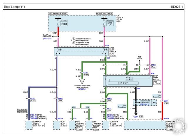
Date Posted: March 05, 2013 at 10:22 AM
this is the brake schematic
Posted By: tameros
Date Posted: March 05, 2013 at 10:36 AM
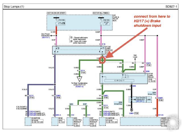
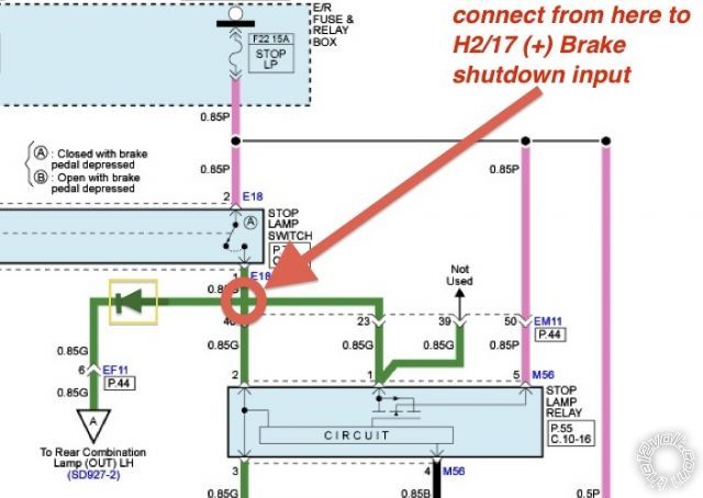
this is the stop lamp and brake switch schematic
Posted By: tameros
Date Posted: March 05, 2013 at 10:46 AM
after the test i will do and tell you, will cut the wire from DBALL pin 6 [Grey (+) Brake status output] connect to R/S unit H2/17 [Brown (+) Brake shutdown input]
and connect H2/17 to the point i marked on the attached picture after contact of the brake pedal switch
Posted By: tameros
Date Posted: March 05, 2013 at 10:50 AM
Sorry i haven't tested yet the brake as you told me as i come home and it is to dark and the garage i was working is not available these days so i think i will do it on thursday
am i right in what i wrote in the previous post?
Posted By: howie ll
Date Posted: March 05, 2013 at 11:29 AM
Yes,exactly there. Either at brake switch or floor loom going from front to back.
-------------
Amateurs assume, don't test and have problems; pros test first. I am not a free install service.
Read the installation manual, do a search here or online for your vehicle wiring before posting.
Posted By: tameros
Date Posted: March 05, 2013 at 1:02 PM
and what about the DBALL pin 6 [Grey (+) Brake status output] should i insulate it and loom it away
Posted By: howie ll
Date Posted: March 05, 2013 at 1:05 PM
Yes.
-------------
Amateurs assume, don't test and have problems; pros test first. I am not a free install service.
Read the installation manual, do a search here or online for your vehicle wiring before posting.
Posted By: tameros
Date Posted: March 05, 2013 at 1:08 PM
Am i becoming a good student 
Posted By: howie ll
Date Posted: March 05, 2013 at 1:10 PM
Oh yes  ------------- Amateurs assume, don't test and have problems; pros test first. I am not a free install service.
Read the installation manual, do a search here or online for your vehicle wiring before posting.
Posted By: tameros
Date Posted: March 05, 2013 at 1:23 PM
Thanks
I made a schematic for sirens & 516L module and sensors
can you look at it and tell me if anything is wrong in it

Posted By: howie ll
Date Posted: March 05, 2013 at 1:34 PM
The lower relay isn't needed, power draw doesn't warrant it.
And it's wired wrong. 
It will blow fuses unless you supply 12V+ to 30 rather than ground.
Secondly, the coil would be activated all the time the alarm was on causing battery drain so leave it out.
Apart from that remembering I know nothing about the 516L, don't like it, always tried to avoid fitting one.  ------------- Amateurs assume, don't test and have problems; pros test first. I am not a free install service.
Read the installation manual, do a search here or online for your vehicle wiring before posting.
Posted By: tameros
Date Posted: March 05, 2013 at 2:24 PM
so you mean i connect ground when armed should be connected to the ground (black wires of sensors) right?
and can it handle 4 sensors?
and the +12V red wires of sensors to constant 12 v, right ?
Posted By: howie ll
Date Posted: March 05, 2013 at 2:57 PM
Yes.
-------------
Amateurs assume, don't test and have problems; pros test first. I am not a free install service.
Read the installation manual, do a search here or online for your vehicle wiring before posting.
Posted By: howie ll
Date Posted: March 05, 2013 at 2:58 PM
But you will sooooo regret fitting all of those sensors.
It will take you longer to adjust than the original install and you will STILL get false alarms.
-------------
Amateurs assume, don't test and have problems; pros test first. I am not a free install service.
Read the installation manual, do a search here or online for your vehicle wiring before posting.
Posted By: tameros
Date Posted: March 05, 2013 at 4:28 PM
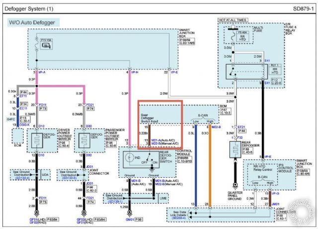
To operate the defogger from R/S unit remote after ignition, please see the following schematic, but i don't know how can i make it on/off
Posted By: tameros
Date Posted: March 05, 2013 at 4:40 PM
i will use output type latch/reset/ignition
Posted By: howie ll
Date Posted: March 05, 2013 at 5:23 PM
No that relay is set up wrong.
Here's your circuit. Brown NEG (-) defogger switch or BCM, blue 20 pin plug, pin 15.
No relay required. Find that wire, with engine running ground it for 1 second, if it works all you need is for the H2/16 wire to be ignition or pulsed for 1-3 seconds.
-------------
Amateurs assume, don't test and have problems; pros test first. I am not a free install service.
Read the installation manual, do a search here or online for your vehicle wiring before posting.
Posted By: tameros
Date Posted: March 05, 2013 at 6:24 PM
Posted By: howie ll
Date Posted: March 06, 2013 at 3:41 AM
Yes, that's the one. It even says pin 15.
-------------
Amateurs assume, don't test and have problems; pros test first. I am not a free install service.
Read the installation manual, do a search here or online for your vehicle wiring before posting.
Posted By: tameros
Date Posted: March 06, 2013 at 4:34 AM
I updated the sensors and sirens circuit can you please tell me if I still have errors
I also read that some sensors must be turned off automatically during remote start, is that true? if yes then which sensors must be turned off and how to do that. Using a relay from an ignition signal?
like H2/11 Pink/White (-) 200 mA Flex relay control output

Posted By: howie ll
Date Posted: March 06, 2013 at 5:44 AM
The NEG side of those Piezo sirens to ground, POS to 87 on the relay.
-------------
Amateurs assume, don't test and have problems; pros test first. I am not a free install service.
Read the installation manual, do a search here or online for your vehicle wiring before posting.
Posted By: howie ll
Date Posted: March 06, 2013 at 5:45 AM
Sensors SHOULD be automatically shut down during R/S.
-------------
Amateurs assume, don't test and have problems; pros test first. I am not a free install service.
Read the installation manual, do a search here or online for your vehicle wiring before posting.
Posted By: offroadzj
Date Posted: March 06, 2013 at 6:03 AM
Something you may want to look into is a Compustar FT DAS. It is a 3-in-1 digital sensor that includes shock, tilt, and forward movement. The only thing I am not sure of is whether it is able to be hardwired or if it can only connect to a Compustar system. It might be something to look into since it will eliminate 2 of your sensors and give you an added forward movement detection sensor.
Someone may be able to chime in here on whether or not it is able to be hardwired (may just be data to/from Compustar systems only)
-------------
Kenny
Owner / Technician
KKD Garage LLC
Albany, NY 12205
Posted By: tameros
Date Posted: March 06, 2013 at 7:43 AM
Howie are the sensors set right, is it better to connect diodes to the connections of the sensor triggers going to 516L module as protection?
Another question i read in a post that i should install diodes on all sensors wires and also on ground when armed. Is that right?
Also read some sensors are positive trigger and others are negative trigger and they said that proximity and tilt are negative trigger, if that is true do i have any positive trigger sensors
Posted By: howie ll
Date Posted: March 06, 2013 at 7:53 AM
Yes to all but the last question.
ALL sensors send a NEG (-) trigger.
I know you won't listen but first try to get the R/S working properly then add those extras in increments.
As for the 516L, I've never known one to work properly and I won't install them.
-------------
Amateurs assume, don't test and have problems; pros test first. I am not a free install service.
Read the installation manual, do a search here or online for your vehicle wiring before posting.
Posted By: tameros
Date Posted: March 06, 2013 at 4:19 PM
all the diodes i ordered came 1N4001
is there difference between 1N4001 & 1N4004
Posted By: tameros
Date Posted: March 07, 2013 at 2:55 PM
Which sensors must be power killed when R/S is on?
Is that way written below right?
Connect the sensors to be killed to a relay pin 87a that is NC, and 30 pin to the sensors +12 VDC constant power source.
R/S unit H2/14 Pink wire (+) 200 mA Ignition 2 output to pin 86, pin 85 to chassis ground
Posted By: tameros
Date Posted: March 08, 2013 at 5:13 PM
Hello Howard
the defogger works fine now after R/S, and set the feature on R/S unit (status 2 output --> pulse rear defogger as the latch doesn't shut off the defogger on second press). when i press again the remote while it is in pulse mode it shuts off the defogger fine, but shows as the first press "Defogger ON". Is there a way that on the second pulse it shows on the remote "Defogger OFF"
I tested the brake pedal wire using DMM without depressing and in ignition on and it shows 0 volt.
I also cut the wire from DBALL pin 6 [Grey (+) Brake status output] to R/S unit H2/17 [Brown (+) Brake shutdown input], insulated and loomed DBALL pin 6 [Grey (+) Brake status output]. Connected H2/17 to the brake pedal line to the stop lamp at the side pannel. The remote start works fine now, it showed only one time "Brake ON" from about 15 test remote starts.
Tomorrow will start to connect the sensors but one by one, connecting one and testing it if OK then other, and so on.
Then will switch kill all sensors except the proximity 508D sensor and test it for a couple of days, if it is working fine alone will test another, I will test each sensor separately for a couple of days.
Then if they all work fine separately and are set right no false alarms and the sensitivity is right not too high not too low, then I will start the last phase to combine them in line together but one by one and check each time for a couple of days for false alarms. Till they work all together in harmony.
What do u think? and waiting for any comments
Posted By: howie ll
Date Posted: March 08, 2013 at 6:06 PM
1N4001 are okay for the sensors, it's just that in Europe and the US, 4004 has become the common one because 1, 2, etc. relate to PIV or peak inverse voltage, 1 = 100, 2 = 200 etc.
With relays, you can get around a 200 volt spike when the relay shuts down.
Hence 400 volts, or 4004.
4001 diodes are fine for the sensors, you'll only be dealing with c. 28 volts.
As for the defogger off, sorry, I haven't a clue.
-------------
Amateurs assume, don't test and have problems; pros test first. I am not a free install service.
Read the installation manual, do a search here or online for your vehicle wiring before posting.
Posted By: tameros
Date Posted: March 08, 2013 at 6:08 PM
I used 1N4001 on the relays, is that OK?
Posted By: howie ll
Date Posted: March 08, 2013 at 6:12 PM
Not really, fingers crossed as they say.
-------------
Amateurs assume, don't test and have problems; pros test first. I am not a free install service.
Read the installation manual, do a search here or online for your vehicle wiring before posting.
Posted By: tameros
Date Posted: March 08, 2013 at 6:14 PM
So better to change them to 1N4004?
Posted By: howie ll
Date Posted: March 08, 2013 at 6:18 PM
Yes, safer than trusting to luck and crossing the fingers, touching wood etc.
Don't worry about my rambling, all good old Christian expressions for luck.
-------------
Amateurs assume, don't test and have problems; pros test first. I am not a free install service.
Read the installation manual, do a search here or online for your vehicle wiring before posting.
Posted By: tameros
Date Posted: March 08, 2013 at 6:19 PM
What do u think about the defogger issue?
Posted By: howie ll
Date Posted: March 08, 2013 at 6:27 PM
No idea and I'm going to bed  ------------- Amateurs assume, don't test and have problems; pros test first. I am not a free install service.
Read the installation manual, do a search here or online for your vehicle wiring before posting.
Posted By: tameros
Date Posted: March 08, 2013 at 6:28 PM
OK, thanks, good night
Posted By: tameros
Date Posted: March 10, 2013 at 6:23 AM
I have installed the 508D and 509U successfully, tested them alone and every sensor of them has a toggle switch (on/off) to the red wire. and the 516L and it is working with remot start, arm, disarm and everything. Didn't install the tilt sensor 507T not 504D nor 506T until i figure out how to deactivate it when remote start and install toggle switch for them.
Changed the relay diodes from 1N4001 to 1N5004 400V protection and 3 amp. Is that relay fine?
I have one thing not working in it. When the 508D gives signal to Viper warn away i get it on my remote, but the 516L doesn't announce the warn away message. Do you have any ideas
Posted By: howie ll
Date Posted: March 10, 2013 at 7:03 AM
Actually too much, change them back to 4004* please. That might be the reason the 508d isn't triggering warn away.
When on, if you get very close do both the green and red LEDs light up.
Lastly wait about 15 seconds before you try and trigger it and have you adjusted the screw pots yet? Very fiddly.
*Needs more current to get past the 54XX diodes ??
-------------
Amateurs assume, don't test and have problems; pros test first. I am not a free install service.
Read the installation manual, do a search here or online for your vehicle wiring before posting.
Posted By: howie ll
Date Posted: March 10, 2013 at 7:10 AM
Forget the 516L; wire directly to the alarm, tell me if the 508d works then. You should know by now I think the 516 is rubbish.
-------------
Amateurs assume, don't test and have problems; pros test first. I am not a free install service.
Read the installation manual, do a search here or online for your vehicle wiring before posting.
Posted By: tameros
Date Posted: March 10, 2013 at 7:12 AM
the 1N5004 is only used on the power of the relays, the 508D has a 1N4001 connected to it, and test the diode polarity with DMM. Cathode towards the sensor.
1N4001 is used on all signal wires only
1N5004 i used it on the relays as surge protection only
if i get very close the red LED only lights up and the alarm is fully triggered, and if i am a little far the green only lights up and i get warn away alert on my HD SST 2-way remote.
Yes i adjusted the outer (warn away) zone first then the inner (trigger) zone. And the 508D works fine with good range.
Posted By: tameros
Date Posted: March 10, 2013 at 7:14 AM
All sirens are working fine and chirps too.
Just still from time to time i get "brake on" on the HD remote when i start to remote start and if a wait a min or so and try again the remote start works normally. Even when i am very far from the car.
Posted By: howie ll
Date Posted: March 10, 2013 at 7:17 AM
Try a "power down and reboot" on the 5902 that's all I could think of ref. the brake switch. Do you have LED rear lights by any chance?
As for the 508d problem, just try by-passing the 516L and go straight to the 5902, tell me if works then.
-------------
Amateurs assume, don't test and have problems; pros test first. I am not a free install service.
Read the installation manual, do a search here or online for your vehicle wiring before posting.
Posted By: tameros
Date Posted: March 10, 2013 at 7:19 AM
Also jumper 3 is set to ON, and the 516L monitors the (+) siren output of the R/S through the brown wire of the 516L module. Or should i better activate the honk output of the R/S unit and then connect it to the brown wire of the 516L module instead of the R/S (+) siren output?
Posted By: howie ll
Date Posted: March 10, 2013 at 7:20 AM
A piece of heartfelt advice or one of my non-PC jokes.
I'll be watching Spurs V Liverpool in about 4 hours, do the same, do NOT go to a local game. Especially don't riot if your team loses.  ------------- Amateurs assume, don't test and have problems; pros test first. I am not a free install service.
Read the installation manual, do a search here or online for your vehicle wiring before posting.
Posted By: howie ll
Date Posted: March 10, 2013 at 7:23 AM
I don't know enough to answer you but if it works on the other sensors, why won't it work on the 508d? Trigger current and voltage should be the same on each.
-------------
Amateurs assume, don't test and have problems; pros test first. I am not a free install service.
Read the installation manual, do a search here or online for your vehicle wiring before posting.
Posted By: tameros
Date Posted: March 10, 2013 at 8:13 AM
How can i reboot the 5902?
I have a spoiler with LED connected the harness.
I think there is no problem at all between the the 508d and the 5902 as I get the warn away trigger paged on my HD 2-way remote. I think maybe it is related to the siren output and the monitoring of the 516L to the chirps and the length of the signal as the warn away of the 516L needs a signal shorter than 0.8 sec
Posted By: tameros
Date Posted: March 10, 2013 at 8:15 AM
and the warn away chirps on the viper but the 516L doesn't play the warn away message
Posted By: howie ll
Date Posted: March 10, 2013 at 9:35 AM
This might be your answer to the brake problem.:-
After your connection to the brake wire add a 1N5404 diode in line with it's band towards the rear, that will prevent any feedback and might cure the problem.
Forget the re boot the problem is with that horrible 516L
I told you to throw it away!!! ------------- Amateurs assume, don't test and have problems; pros test first. I am not a free install service.
Read the installation manual, do a search here or online for your vehicle wiring before posting.
Posted By: tameros
Date Posted: March 10, 2013 at 10:51 AM
You mean like in the photo?
Posted By: howie ll
Date Posted: March 10, 2013 at 11:03 AM
Yes, place the diode below your connection with the band towards the brake light, it will block any feedback from the brake lights.
-------------
Amateurs assume, don't test and have problems; pros test first. I am not a free install service.
Read the installation manual, do a search here or online for your vehicle wiring before posting.
Posted By: tameros
Date Posted: March 10, 2013 at 11:43 AM
OK got it
Posted By: tameros
Date Posted: March 12, 2013 at 9:09 AM
Hii Howard
I tested the wire going to the back giving me 12 VDC when i depress the brake and cut it, then before installing the diode tested the remote start while it is cut. First time the R/S worked well, but when i deactivated the remote start and tried again it gave me again "Brake ON" then the second time the same and whenever i try after it gave "Brake ON"
So i don't think it is the spoiler led problem, so what do u think it can be?
Posted By: offroadzj
Date Posted: March 12, 2013 at 11:00 AM
Sorry if this has already been covered, but did you use W2W between the bypass and the unit or D2D? Is the brake wire connected to anything after you cut it?
-------------
Kenny
Owner / Technician
KKD Garage LLC
Albany, NY 12205
Posted By: tameros
Date Posted: March 12, 2013 at 11:09 AM
i used W2W
I have 2 pending problems
first is the one i posted earlier today, where i connected the brake pedal output to tail lights to H2/17 Brown on Viper 5902 and the connection with the DBALL is cut and the Grey wire ( + Brake status output) of the DBALL (Red Harness) is insulated and loomed away.
second problem the 516L green warn away wire is connected to the 508D sensor green wire on MUX cable and is connected to the R/S unit. I get warn away on my remote 2 way but the 516L doesn't message "stay back" the sirens only chirp
Posted By: offroadzj
Date Posted: March 12, 2013 at 1:21 PM
Put your meter on the brake wire coming out of the Viper and see if it somehow shows 12 volts at any point during a failed remote start attempt.
-------------
Kenny
Owner / Technician
KKD Garage LLC
Albany, NY 12205
Posted By: tameros
Date Posted: March 12, 2013 at 1:44 PM
OK i will try this.
If this is happening what does that mean, i have already added a diode to the main line to the tail lights as i have a led spoiler installed.
Posted By: offroadzj
Date Posted: March 12, 2013 at 2:27 PM
If you are getting 12volts directly from the brain (without anything else being connected to that wire) then you almost definitely have a bad remote starter.
-------------
Kenny
Owner / Technician
KKD Garage LLC
Albany, NY 12205
Posted By: tameros
Date Posted: March 12, 2013 at 2:48 PM
OK
what about the warn away message of 516L, why doesn't it play if the sirens chirps warn away and remote shows warn away and the 516L system announces all other messages?
Posted By: tameros
Date Posted: March 12, 2013 at 2:51 PM
is there a way to test the signal of the green wire of the 508D sensor if it is less than 0.8 sec or longer, as i read on the manual that warn away must be less than 0.8 sec, am i right?
Posted By: offroadzj
Date Posted: March 12, 2013 at 5:12 PM
I have no idea on the 516L... never installed one.
-------------
Kenny
Owner / Technician
KKD Garage LLC
Albany, NY 12205
Posted By: howie ll
Date Posted: March 12, 2013 at 5:16 PM
Sorry have to work sometimes but I was thinking bad siren brain, I was going to suggest disconnecting completely from the brake wire and see if it still faulted the same, if so bad unit.
As for the 516, I see Kenny was more diplomatic about them than me.
-------------
Amateurs assume, don't test and have problems; pros test first. I am not a free install service.
Read the installation manual, do a search here or online for your vehicle wiring before posting.
Posted By: tameros
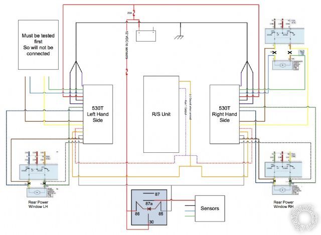
Date Posted: March 13, 2013 at 12:44 PM
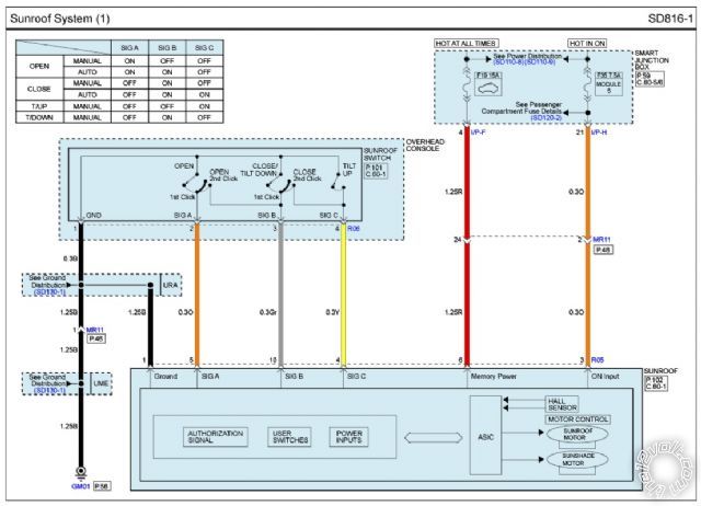
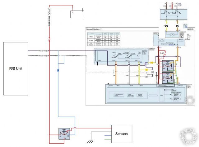
Can the 529T unit be installed on my sun roof, or there is no access to the motor wires?
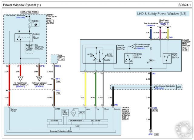
For the 530T is it possible on the driver window that has a safety module
I have the rest of the windows type A both ends of motor rest at ground right?
Sunroof Schematic
Windows Schematic 1/3
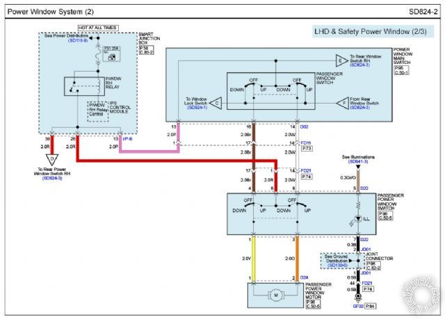
Windows Schematic 2/3

Windows Schematic 3/3
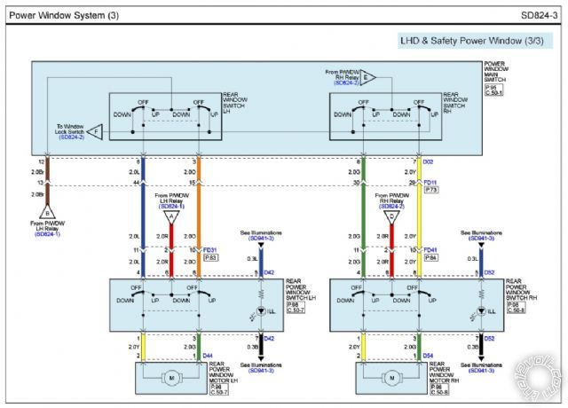
Posted By: howie ll
Date Posted: March 13, 2013 at 12:55 PM
In the first picture, you need to make orange at 3 constant, then ground either the grey or yellow to tilt close or slide close.
So you have an aux going to 85 of your relay, 86 87 constant fused 5 amps, cut the orange, 30 sunroof module and 87a to fuse
Diode across the relay and a "Y" split, both sides diodes and the other side of that aux, set for about 7 seconds linked to arm to either the grey or yellow.
Bet it does the trick.
Ref the windows, you need to get at the motor wires, BTW the bottom 2 diagrams are the same.
-------------
Amateurs assume, don't test and have problems; pros test first. I am not a free install service.
Read the installation manual, do a search here or online for your vehicle wiring before posting.
Posted By: tameros
Date Posted: March 13, 2013 at 2:18 PM
You mean this is for closing the sunroof only, i think that the yellow is only to tilt the sunroof up as in the table in the top left of the first picture (sunroof schematic)
To tilt close (down) should be signal B (grey wire is the only that should be on), it takes about 2 secs (timed it with stop watch) to tilt up or down so should i still time the AUX to 7 sec or enough about 3 or 4 secs.
i don't understand "Diode across the relay and a "Y" split, both sides diodes and the other side of that aux"
and how will i imulate the switch on of the grey wire, should i use another relay?
Posted By: tameros
Date Posted: March 13, 2013 at 2:26 PM
And what about the power safety window of the driver side, schematic of windows 1/3
Posted By: howie ll
Date Posted: March 13, 2013 at 2:49 PM
Try this:- roof.bmp
Still can't see the driver's motor.
You are attempting too much, any mistakes will compound each other/multiply.
Get ONE THING at a TIME RIGHT. ------------- Amateurs assume, don't test and have problems; pros test first. I am not a free install service.
Read the installation manual, do a search here or online for your vehicle wiring before posting.
Posted By: tameros
Date Posted: March 13, 2013 at 2:59 PM
I am sorry i inserted schematic three 2 times, here it is
Posted By: howie ll
Date Posted: March 13, 2013 at 3:03 PM
If either green, yellow or grey don't show 12V+ on up/down, don't touch it.
Try and measure what the switch is doing.
-------------
Amateurs assume, don't test and have problems; pros test first. I am not a free install service.
Read the installation manual, do a search here or online for your vehicle wiring before posting.
Posted By: tameros
Date Posted: March 13, 2013 at 3:04 PM
OK I will test it
Posted By: tameros
Date Posted: March 14, 2013 at 8:22 AM
i made the schematics for installation of the window modules and for sun roof as you advised me
Posted By: howie ll
Date Posted: March 14, 2013 at 10:36 AM
In theory you shouldn't need either relay, I'm sure that whilst R/S is on those sensors are disabled.
-------------
Amateurs assume, don't test and have problems; pros test first. I am not a free install service.
Read the installation manual, do a search here or online for your vehicle wiring before posting.
|