diode isolating circuits
Printed From: the12volt.com
Forum Name: Car Security and Convenience
Forum Discription: Car Alarms, Keyless Entries, Remote Starters, Immobilizer Bypasses, Sensors, Door Locks, Window Modules, Heated Mirrors, Heated Seats, etc.
URL: https://www.the12volt.com/installbay/forum_posts.asp?tid=133662
Printed Date: May 12, 2026 at 10:10 AM
Topic: diode isolating circuits
Posted By: tbothur0709
Subject: diode isolating circuits
Date Posted: February 22, 2013 at 9:52 AM
Using the door lock relay set up detailed on bulldog security for a 1 wire negative lock system (02 Ram 1500), do you have to isolate the two circuits since they both go into one wire or does the relay isolate the circuits? My door locks don't work properly with the relay set up that they use, the switch on my door works backwards and the locks don't work with the clicker on the remote start.
Link to diagram:
https://diagrams.marktoonen.nl/DOWNLOADS/26500_RAM-FULL-SIZE-PICKUP-_DODGE%20RAM%201%20WIRE%20JBS%20UNITS.pdf
Replies:
Posted By: lucasoil4u
Date Posted: February 22, 2013 at 10:31 AM
you shouldnt need to diode isolate. you either have the relays wired wrong or the wrong resistors. Keep in mind you need to tap in a 2 different spots for the resistors. if you put them in the same spot resistance will be off.
Posted By: offroadzj
Date Posted: February 22, 2013 at 11:17 AM
Yea, it sounds like you definitely have the wiring wrong. The relays shouldn't activate until you press the lock / unlock on the remote start and the factory wire should not see any added resistance without those relays activated.
Which unit do you have? Are the relays external (1st diagram) or external (2nd diagram)?
-------------
Kenny
Owner / Technician
KKD Garage LLC
Albany, NY 12205
Posted By: tbothur0709
Date Posted: February 22, 2013 at 11:18 AM
Right now I have my relays wired up like the diagram shows, but I have my reaistors coming together into one wire and tapping in at one spot. I can take a jumper from ground to each wire (lock and unlock with resistor) at the relay and the locks work as they should. Even though it works normal from that end would the wires coming together cause the switch to be backwards? Do I still need to separate them?
Posted By: tbothur0709
Date Posted: February 22, 2013 at 11:27 AM
I have the Clifford 1.1L. I can't find anythig to say whether or not it has onboard door lock relays or not. I know that one wire pulses a negative for unlock at the same time the other pulses positive. I'm nervous to hook it up without the relays without knowing. Will the positive pulse from the module harm the negative door lock circuit? Should I try it without the added relays?
Posted By: howie ll
Date Posted: February 22, 2013 at 11:35 AM
Needs two relays then each outputs two a resistor which then join together to join the vehicle wire.
Diode the lock outputs since they appear to be flip-flop, 1N4004, band toward 1.1L also if using separate relays, same diodes across coil, band to POS side of coil.
-------------
Amateurs assume, don't test and have problems; pros test first. I am not a free install service.
Read the installation manual, do a search here or online for your vehicle wiring before posting.
Posted By: tbothur0709
Date Posted: February 22, 2013 at 11:44 AM
So add a diode to each wire before they join together. Band away from the vehicle harness, and one across the coil on the resistor band towards positive. What purpose does it serve to place one on the relay? How can I tell if the module has on board door lock relays?
Posted By: howie ll
Date Posted: February 22, 2013 at 11:53 AM
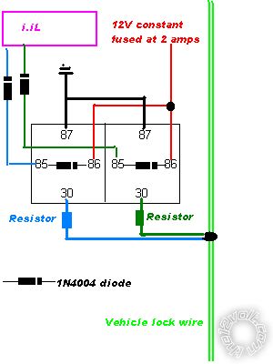
Try this the diodes will "condition" the lock wires from the 1.1L:- 687_resistive_locks.bmp------------- Amateurs assume, don't test and have problems; pros test first. I am not a free install service.
Read the installation manual, do a search here or online for your vehicle wiring before posting.
Posted By: howie ll
Date Posted: February 22, 2013 at 11:56 AM
Two lock output + no onboard relays, 6 wire - onboard relays.
If you had onboard relays you'd only need the resistors.
The relay diode is a quenching diode to suppress the shut-down EMP/EMF generated about 200volts. It can destroy your 1.1.L.
-------------
Amateurs assume, don't test and have problems; pros test first. I am not a free install service.
Read the installation manual, do a search here or online for your vehicle wiring before posting.
Posted By: tbothur0709
Date Posted: February 22, 2013 at 12:03 PM
So do I need to add a diode to all relays that I put in? (Dome light relay and park light relay?
Posted By: howie ll
Date Posted: February 22, 2013 at 12:15 PM
Any relay fed from a low current aux output from the 1.1L should be dioded.
You will get away with it 9 out of 10 times, the tenth being the time that costs you a new unit.
-------------
Amateurs assume, don't test and have problems; pros test first. I am not a free install service.
Read the installation manual, do a search here or online for your vehicle wiring before posting.
Posted By: tbothur0709
Date Posted: February 22, 2013 at 12:18 PM
Well then sounds like I need to go buy some more diodes. Do them the same as the picture? One on the relay and one on the wire to the module? And as far as the door locks, this should fix the problem of the backwards locks from the door switch?
Posted By: howie ll
Date Posted: February 22, 2013 at 12:19 PM
Yes, exactly.
-------------
Amateurs assume, don't test and have problems; pros test first. I am not a free install service.
Read the installation manual, do a search here or online for your vehicle wiring before posting.
Posted By: tbothur0709
Date Posted: March 03, 2013 at 12:17 PM
Well I got to digging on my alarm, and my issue wasn't the diodes. With everything connected (properly) there is a measurement of 1.2v across the coil on both resistors. I removed all power from the resistors, and isolated the source to the lock wire. With the lock wire disconnected, 0.0 v across the coil, connected, 1.2v (this is with the control module removed from the circuit)
With the relay disconnected from the vehicles lock wire, the lock wire has no voltage on it. I can only assume now that the relays are bad?
My next step is to rewrite the relays because I don't like them. Since the module puts out a -lock +unlock on one wire and a +lock -unlock on the other wire, can't I just wore the relay coil to ground and use the +signal from the module to trigger the relay? That way there isn't constant 12v power to them. I'm assuming it doesn't matter how you trigger the relay, as long as it is triggered it will connect 87 (ground) to 30 (ground through resistor to door lock wire).
Thanks for all of the knowledgable input!!
|