06 f350 alarm remote start
Printed From: the12volt.com
Forum Name: Car Security and Convenience
Forum Discription: Car Alarms, Keyless Entries, Remote Starters, Immobilizer Bypasses, Sensors, Door Locks, Window Modules, Heated Mirrors, Heated Seats, etc.
URL: https://www.the12volt.com/installbay/forum_posts.asp?tid=134009
Printed Date: March 31, 2026 at 10:28 AM
Topic: 06 f350 alarm remote start
Posted By: ace_boy2099
Subject: 06 f350 alarm remote start
Date Posted: April 08, 2013 at 3:23 PM
Hey all, I have a 05 F350 (Automatic Diesel) I am planning on installing an alarm/Remote Start Combo on and I have a question concerning the locks. I think, by reading the install manuals i've downloaded, that I can rig a way to make it so that i can wire an arm/disarm input (using options 4-06 and 4-07 to option 3 or 4) to the after market alarm from the trucks lock system this way I can still use the door keypad to access the truck. What I am thinking of is locating the lock and unlock wires from the VSM and cut them then place a diode on the door switch side to prevent the switches in the door from disarming the alarm but still have it so that the factory keyfob remote/Door keypad can unlock and lock the truck. I have read through the instructions and looked over wiring diagrams and think I have a good plan of attack on this but want to know if anyone else has done this or knows about this and can shed a little more light on my plans.
I have installed this system on an 06 I had but I have gotten rid of that for this truck and am trying to put the alarm in this now, But this time I have to deal with power locks too, and would like it the way I want if at all possible.
What I am working with:
2005 F350 Diesel with Factory Remote Keyless
Compustar CM6000 Alarm/Remote Start System
P9000SS Antenna/Remote Kit
I can upload documents and such with what I have read and looked at to figure this out, Just let me know if you need it or would like to see it.
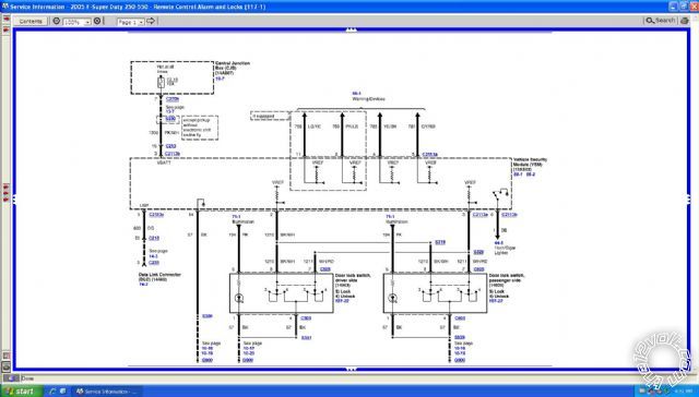
This is the wire diagram I am thinking will work for what I am attempting. Can anyone else tell? I think the wires I need for this is the BK/WH & WH/RD in the center of the picture.
Replies:
Posted By: buddholly
Date Posted: April 08, 2013 at 11:36 PM
It's impossible to read any of the image.
-------------
Posted By: ace_boy2099
Date Posted: April 09, 2013 at 12:00 AM
Sorry, I thought it would upload as a "Click to expand" thing.

*Pre-emptive sorry just incase this shows up too big*
Posted By: ace_boy2099
Date Posted: April 12, 2013 at 1:31 AM
upon discovering offroadzj's "wiring template" thing that he made I downlaoded and filled it out, Here is a copy and paste of it.
Vehicle Information:
2005 Ford F350 Diesel with Remote Keyless Entry
Alarm / Remote Start Unit:
Compustar CM6000 Alarm/Remote Start (P9000SS Remotes/antenna)
Bypass Module:
None Needed, No PATS
Alarm / Remote Start / Bypass Unit
Vehicle
Connection
Color
Description
Color
Polarity
Location:
CN1 P1
White
12V Accessory
RED / Black
& Grey / YELLOW ?
+
Ignition Harness
CN1 P2
Yellow
12V to Starter
Green
+
Ignition Harness
CN1 P3
Green
12V to Ignition
RED / Green
+
Ignition Harness
CN1 P4
Black
Ground (-)
N/A
-
Body Ground
CN1 P5 (X2)
Red (X2)
12V Constant
N/A
+
FuseBox Power Bolt
CN1 P6
GREEN / WHITE
12V Parking light Output
Brown
+
FuseBox or VSM Green connector Pin 2
AR P85
Violet
- Trigger from alarm
WHITE/ Black
-
Alarm Brain/Control Module
AR P86
Red (Thin Prewired)
+12v Trigger
N/A
+
N/A
AR P87
Red
+12V Constant Input
Red
+
Alarm Main Harness (CN1P5)
AR P30
Blue
+12V Output (2nd Accessory +)
Grey / YELLOW
or Dark Blue/Light Green ?
+
Ignition Harness
CN2 P1
Red
Battery Backup +
CN2 P2
Black
Battery Backup -
CN3 P1
Blue
-250mA Output to Starter Kill
Blue
Prewired to Starter-Kill Relay
CN3 P2
ORANGE / Black
- Parking Light Reminder
CN3 P3
GREEN / WHITE
-250mA 2nd Parking Light Output (POC1)
CN3 P4
Light Blue
- Emergency/Parking Brake Input
Light GREEN/ Red
-
At Parking Brake
CN3 P5
RED / Black
-250mA 2nd Starter Output (POC2)
CN3 P6
Light Blue/White
+ Foot Brake Input
Green
+
At Brake Pedal
CN3 P7
GREEN / WHITE
-250mA 2nd Ignition Output (POC3)
CN3 P8
Violet/Black
-Trunk Trigger Input
CN3 P9
WHITE/ Black
-250mA 2nd Accessory Output (POC4)
Violet
-
Pin 85 Additional Relay with Alarm
CN3 P10
RED / White
+/- Door Trigger Input (Select Polarity by Dip Switch)
Various
+ ?
Direct to Vehicle, Diode Each separate
CN3 P11
Black
-250mA Status Out (GWR) (POC5)
CN3 P12
BROWN / White
+/- Key Sense/Glow Plug Input (Select Polarity by Dip Switch)
BLACK/ Pink
-
At Steering Wheel (Key Sense)
CN3 P13
ORANGE / Black
-250mA Rearm Output (POC6)
CN3 P14
Pink
- Slave/Timer Start Input
CN3 P15
ORANGE / White
-250mA Disarm Output (POC7)
CN3 P16
Yellow/Black
Engine Sensing Input (Alt./Tach/Battery)
GREEN / WHITE
PTO Wires behind FuseBox
CN3 P17
White
-250mA Horn Output (POC8)
Dark Blue
-
Steering Wheel or VSM-Pin6 of Green Plug
CN3 P18
Grey/Black
- Hood Pin Input
N/A
-
To Hood Pin at Front of Truck
CN3 P19
Violet
-250mA Aux 1 Output (POC9)
CN3 P20
Brown
+ 12V Output to Siren
N/A
+
To Siren Under Hood
CN4 P1~20
Black Connector
ADS Blade Connector
CN5 P1
*NONE*
N/A
CN5 P2
Violet/White
-250mA Trunk Release Output
CN5 P3
ORANGE / Black
-250mA Priority Unlock Output
RED / Orange
-
VSM (Grey Connector Pin 7) or Drivers Kick Panel (DKP)
CN5 P4
Blue
-250mA Unlock Output
Pink/Orange
-
VSM (Grey Connector Pin 6?) or Drivers Kick Panel (DKP)
CN5 P5
Blue/Black
-250mA Lock Output
Pink/Black
-
VSM (Grey Connector Pin 1) or Drivers Kick Panel (DKP)
CN5 P6
*NONE*
N/A
CN6 P1~4
Blue Connector
RS232 Connector
CN7 P1~3
White Connector
Valet Button
CN8 P1~2
Blue Connector
Temp Sensor
CN9 P1~4
Blue Connector
4Pin Antenna
CN10 P1~6
Blue Connector
6Pin Antenna
CN11 P1~2
White Connector
LED (Don't use together with the RPS-Touch)
N/A
N/A
N/A
CN12 P1~4
White Connector
RPS Module
RPS-Touch on Windshield
CN13 P1~4
Red Connector
Pre-Wired Shock Sensor
CN14 P1
Black
-
CN14 P2
BLACK/ White
-Warning Input*
{Also Option 4-07 changes to +/- Arm Output}
?
WHITE/ Red
- ?
VSM (Grey Connector Pin 3)
Diode between VSM/A.M. Alarm & Truck
CN14 P3
Red
+12V
CN14 P4
Grey/White
-(Pre Warning / Warning) Input*
{Also Option 4-06 changes to +/- Disarm Output}
?
BLACK/ White
- ?
VSM (Grey Connector Pin 2)
Diode between VSM/A.M. Alarm & Truck
Dome Light Supervision
BLACK/ Light Blue
+
Pass Kick Panel (PKP) or Cluster Blue connector Pin 26
Reverse Lights
BLACK/ Pink
+
Fuse Box Black 8-Pin Connector Pin X
Hazard Lights
Right Turn Signal
ORANGE / Lite Blue - Rear
WHITE/ Light Blue - Front
+
Turn Signal Switch
Left Turn Signal
Light GREEN/ Orange - Rear
Light GREEN / WHITE - Front
+
Turn Signal Switch
Sorry about the bold formatting thingies excel put around the bold parts, btw, That is the option I am planning to go with on my install.
Posted By: tonanzith
Date Posted: April 12, 2013 at 1:32 PM
If I understand you correctly you want to be able to use the factory keypad to disarm the after market system. I looked through the manual for the system you have and i did NOT see a disarm input wire. There is a factory disarm wire but that is NOT the same.. that wire is used for the after market system to disarm a factory alarm. It doesn't work in reverse. To achieve what you want you would have to use a system design to have factory add on capabilities i.e. a designated arm and disarm input wire(s) and a disarm defeat feature. I MAY be wrong but I did NOT see these features or wires listed in your systems manual. I would also recommend a more appropriate wire diagram. I can provide you with either a Directed or Audiovox diagram if you like. Just let me know.
-------------
Gary Sather
Posted By: ace_boy2099
Date Posted: April 12, 2013 at 3:57 PM
The manual I have in the options Table 4-06 and 4-07 says you can change the green (cn13) plug from a second warning/trigger input to either a positive or negative (selectable by option choice) disarm and arm respectively.
I figured I'd have to cut the vehicles wiring and put in diodes in order to seperate it from the door switches so you can't just get in the truck then hit the door switch to de-activate the alarm. Then I figured I'd have to make the arm wire through a relay to only be active when the vehicle isn't running, That way I don't activate the alarm accidentally while the vehicle is running.
however, I am now second guessing that may not work because the only thing the diodes will do is keep the vehicle from locking all together by means of the door switches, Unless someone knows what wire(s) do the factory keyless arm&disarm and their polarity.
Posted By: tonanzith
Date Posted: April 12, 2013 at 7:34 PM
If your alarm has a disarm defeat feature you do not need diodes.
Vehicles with keyless entry, the lock wire is WHITE/ red (-), in the driver kick, door harness or also at the VSM, gray plug, pin 3. The VSM (Vehicle Security Module) is to the right of the accelerator pedal above the transmission hump below the radio. Not accessible from radio opening.
Vehicles with keyless entry, the unlock wire is BLACK/ white (-), in the driver kick, door harness or also at the VSM, gray plug, pin 2. The VSM (Vehicle Security Module) is to the right of the accelerator pedal above the transmission hump below the radio. Not accessible from radio opening. Vehicles with keyless entry the VSM shuts down after the doors have been locked for a certain time period, to wake up the system refer to Tech Doc 1094.
-------------
Gary Sather
Posted By: tonanzith
Date Posted: April 12, 2013 at 7:37 PM
you could also consider using the parking light pulse to arm and disarm the alarm if they flash when locking and unlocking using the keypad or remote.
-------------
Gary Sather
Posted By: ace_boy2099
Date Posted: April 13, 2013 at 1:11 AM
tonanzith wrote:
If your alarm has a disarm defeat feature you do not need diodes.
I am not aware of a disarm defeat feature aside from the valet button thing which needs a code/procedure to activate, it's not just a wire.
tonanzith wrote:
Vehicles with keyless entry the VSM shuts down after the doors have been locked for a certain time period
I had heard/read about that so I am aware, I just have to make the diagram physical.
tonanzith wrote:
you could also consider using the parking light pulse to arm and disarm the alarm if they flash when locking and unlocking using the keypad or remote.
I'd have a couple issues with this idea, first: While my parking lights do flash on arm/lock they don't with disarm/unlock; Second: how would that work to get it to just register the pulsed lights and not arm itself anytime I turn the parking lights (/headlights) on?
Does anyone know if there is an actual factory arm/disarm output from the stock keyless module thing and what wires they may be? After second guessing myself about the diodes and such on the lock/unlock wires (WHITE/ red, BLACK/ white) I am having a hard time figuring how the diodes should go, any sugestions?
Thanks for all the replies and help; past, present, and future.
Posted By: tonanzith
Date Posted: April 13, 2013 at 11:09 AM
A reputable alarm will have a disarm defeat wire if it has factory add on capabilities. It would need to see both the unlock pulse and disarm defeat pulse to disarm the system. So I'd your parking lights don't flash on disarm I.e. unlocking from the keypad then you need to find another source. Such as any light that comes on when unlocking from the keypad but not just from the switch. This doesn't mean any time that light or parking light comes on the alarm arms or disarms it needs both pulses and also when your ignition is on the system is off. So it's not like it can arm when your driving down the road. I have reviewed your systems manual AGAIN and do NOT believe your system is capable of what you want.
-------------
Gary Sather
Posted By: ace_boy2099
Date Posted: April 13, 2013 at 4:21 PM
tonanzith wrote:
A reputable alarm will have a disarm defeat wire if it has factory add on capabilities. It would need to see both the unlock pulse and disarm defeat pulse to disarm the system. So I'd your parking lights don't flash on disarm I.e. unlocking from the keypad then you need to find another source. Such as any light that comes on when unlocking from the keypad but not just from the switch. This doesn't mean any time that light or parking light comes on the alarm arms or disarms it needs both pulses and also when your ignition is on the system is off. So it's not like it can arm when your driving down the road. I have reviewed your systems manual AGAIN and do NOT believe your system is capable of what you want.
Does that disarm defeat pulse thing have a different name I could look for? I just read through the whole install guide I have for the CM6000 and I didn't see anything like that aside from the valet switch which is a 3-wire pre-wired button that works in conjuction with the ignition and/or the 2-way remote.
also, I took a clip of where I read about the arm/disarm input from my control manual here is the link, https://img854.imageshack.us/img854/7422/406and407ofcompustarcm6.jpg How old is your manual? Mine says it is (C)2009 but doesn't specify a version number.
Side note to any moderators who may see this, Since I can't edit my stuff yet (and they aren't the most recent posts), could you take my pics above and just turn them into links like I have in this post, Thanks.
Posted By: ace_boy2099
Date Posted: April 13, 2013 at 4:48 PM
I just did a google search and found a (C)2011 (V6.07) copy of the CM6000 Install manual and I checked and still see the option on its menu too, What I had was apparently a (C) 2009 V2 maual.
Posted By: tonanzith
Date Posted: April 13, 2013 at 4:49 PM
OK so I looked at that image. It does look like that would work. However after scouring the manual there is no disarm defeat which means there is no real way to keep someone from using the lock/unlock switch from disarming the system. Best solution is to find a light that comes on when the truck is unlocked with the factory remote or keypad but that doesn't come on when simply using the switch. this COULD be a parking light, dash light or even sometimes a light near the third brake light if you have one on the top rear of the cab. In other words the system would not disarm if someone used the switch because it wouldn't see the pulse that it needs to disarm.
If I am NOT mistaken you should be able to use a pulse that goes to one of the white lights by the third brake light. I believe when you disarm with the keypad and or factory remote there are two white lights to either side of the third brake light that illuminate that DONT turn on when simply using the unlock switch. if this is the case the this would work for what you need.
-------------
Gary Sather
Posted By: ace_boy2099
Date Posted: May 18, 2013 at 1:34 PM
Ok, with all the above stuff aside i have a couple questions,.I have the alarm/remote start installed and working except the gem wake up thing so far, (and the ground for the siren).
If i am not mistaken that gem wake up thing is for after 5 min or so when the vsm "goes to sleep" , right? Or is the VSM something different from the GEM that relay configuration was designed for? I had read that I need to have that on my truck but havn't gotten to making it up yet.
the unit has door lock , Door Unlock, and Priority Unlock wires on Connector 4. Do these go to the Lock and Unlock (WHITE/ Red, BLACK/ White) wires or do they go to the lock motor wires (Pink/Orange, RED / Orange, Pink/Black)? I currently have it hooked up to the motor wires.but the locks don't work with the compustar remote (tested immediately after locking/unlocking with factory remote to make sure the vsm is awake).
I read on a topic here somewhere (google search result) something about putting a diode on the dome light Supervision wire (Door Sense wire), am I suppose to or is it just a direct wire? While on this subject what does "Auto" mean in the options menu for domelight Delay? My other options are off, 5 sec, and 45sec. Does this have anything to do with supervision or is this for a dome light output?
Once I get the locks working I'll see if the dome lights go out when the vehicle locks, If not that will be another question for another time.
Thanks for any help/info anyone has/provides.
Ace_boy2786
Posted By: ace_boy2099
Date Posted: May 21, 2013 at 3:49 AM
I don't know who all is watching or looking at this thread but if anyone knows if there is a way to check the firmware of a control module (or how to make sure a flash was accepted) without the module installed in a vehicle (ex: hooked to the computer or something) I would be very welcome to hear about it, I would like to check this control module I tried to flash, I swapped my second module that I updated with a working module in my truck and once I made all the connections and then re-connected the ground the module started to make or cause (I couldn't tell in the little space I was in) a clicking as if a relay was continously being activated and de-activated. I want to make sure nothing was messed up and the module is flashed correctly, the truck seems fine without te module(s) installed, with the little space I got frustrated and didn't try re-hooking in the working, un-updated, module.
P.S. I've also been in / watching this thread too...cm6000, RPS Touch Pager, What Gives?
Posted By: ace_boy2099
Date Posted: May 26, 2013 at 3:40 PM
Update for anyone wondering and/or reading this.
I found out that if you have an OP500 (or at minimum an ADS-USB adapter kit) You can go to the idatalink site and use the weblink updater software. once you update WebLink to ver 6.3 you can update just the control modules with-out a blade module, prior to that you need a blade module to do anything, or so I'm told.
ok, I have the alarm starter installed, I'm only missing a couple features that I would like/that don't work, They are as follows
1. Unlock/Disarm and Lock/Arm using factory fobs and door keypad; But not the interior door switches. If anyone knows how to wire this PLEASE LET ME KNOW, Thank You.
2. Locks don't seem to be working with the alarm. I have the Lock wire connected to the Pink/Black, Unlock connected to Pink/Orange, and Priority Unlock to RED / Orange all direct to vehicles wiring. Is this correct, or should I have connected to the WHITE/ Red and BLACK/ White and not have Priority Unlock (which I would like to have)? (Yes the GEM wakeup is connected to the vehicle as the diagram states and set the alarm to double pulse on unlock.)
3. I have to double check my Dip switches for my Door Trigger polarity, I don't remember what I had it set to and I didn't think to check before i re-installed. Once I do that I will try and connect them directly to isolated Door trigger leads, If that don't work I will have to try and change the dip switch and connect to dome supervision. I tested the door trigger wires before hand and with a 3-light test light (correct power connection, +, -) it shows red (+) then green (-) when a door is opened, with a multimeter it shows 12v when closed and like ?6v when open. however, I noticed that if i wait like ?45sec then the constant red goes to a quick flashing red, will this cause a false in the system?
If I have to use domelight supervision, and the light don't go off when I press the lock button, how do I set it to sense when the light goes out? can I just set option setting 3-3 to IV? or do I have to use option II or III?
With updating the control module to V7.00 via idatalinks WebLink the RPS-Touch is now flashing like it should when armed, I have yet to try and program it though on account the door triggers and locks aren't working... yet...
Posted By: ace_boy2099
Date Posted: May 28, 2013 at 9:29 AM
UPDATE:
I have both the door triggersand the door locks kind-of figured out, For the locks I changed from the lock motor wires (RED / orange, pink/orange, pink/black) to the lock and unlock relay wires (BLACK/ white, WHITE/ red) and the locks are now working with the alarm, Just now I don't have the drivers priority lock which I would like to be able to retain. As for the door trigger I currently have it hooked up to domelight supervision with auto dome delay which seems to work, I don't seem to be getting a flase yet.
Im still up for anyone with info to help me get the features I want on this thing working., Thanks.
Posted By: ace_boy2099
Date Posted: June 07, 2013 at 7:35 AM
Pg.2 - 16\782 BUMP
Stilll looking to find out how to wire to work as desired. any info that can help me i'd be glad to hear.
Posted By: ace_boy2099
Date Posted: June 16, 2013 at 7:40 AM
pg2 - 17-895 bump
Posted By: ace_boy2099
Date Posted: June 23, 2013 at 4:44 AM
pg 2 - 18/957 bump
no one aable to assist with factory keypad retention ideas yet?
Posted By: ace_boy2099
Date Posted: July 07, 2013 at 10:25 PM
Page 2 - 19/1337bump
[spoiler] haha, topic view is at 1337, :P
P.S. I hope this forum code works here...[/spoiler]
Posted By: ace_boy2099
Date Posted: August 21, 2013 at 3:36 PM
Page 4 - 20/5617 bump
Posted By: kreg357
Date Posted: August 21, 2013 at 6:55 PM
To get the Compustar to do Progressive Unlock do this. Use a relay to unlock the Drivers Door Lock Motor.
Relay Pin 85 to Compustar CN5-3 ORANGE / Black Priority Unlock
Relay Pin 86 & 87 to +12V constant thru 15 Amp fuse
Relay Pin 87a to F350 Drivers Unlock Motor wire - cut - switch side ( RED / Orange? )
Relay Pin 30 to F350 Drivers Unlock Motor wire - cut - motor side ( RED / Orange? )
Additionally you must change the Compustar programming Menu Feature 1 - 3 to Option 2
Leave the CN5-4 Blue Unlock connected to the F350 BLACK/ White (-) Unlock wire.
-------------
Soldering is fun!
|
