spall door locks with dual swithches
Printed From: the12volt.com
Forum Name: Car Security and Convenience
Forum Discription: Car Alarms, Keyless Entries, Remote Starters, Immobilizer Bypasses, Sensors, Door Locks, Window Modules, Heated Mirrors, Heated Seats, etc.
URL: https://www.the12volt.com/installbay/forum_posts.asp?tid=134606
Printed Date: April 27, 2026 at 7:21 PM
Topic: spall door locks with dual swithches
Posted By: jr789
Subject: spall door locks with dual swithches
Date Posted: July 26, 2013 at 8:47 PM
Hi
I have a question and hope someone can give me a definitive answer to this problem.
I have a 1988 f150 and decided to install Spall aftermarket door locks , there are only a left and a right unit. I got the brilliant idea to install the spall door lock switches one for each side, the switches are 2 wire and the system was designed to have one master switch for the driver. I bought and installed a switch on both doors, after consulting a friend they advised me to take my two hot wires from the drivers powered up actuator and connect them to the two respective wires on the passenger side actuator , there by the master (drivers) switch would always override the passenger switch but the passenger could still actuate the passengers side. The end result is that they are now dependent on each other rather than the master overriding the passengers side.
Can someone walk me through this ?
Your help is greatly appreciated
Thanks
Replies:
Posted By: the12volt
Date Posted: July 27, 2013 at 9:27 AM
I would wire the actuators as shown in the following diagram and parallel the two switches. The switches do not need to be isolated. -------------  the12volt Support the12volt.com the12volt Support the12volt.com
Posted By: jr789
Date Posted: July 28, 2013 at 12:58 AM
Thank you for your help ,
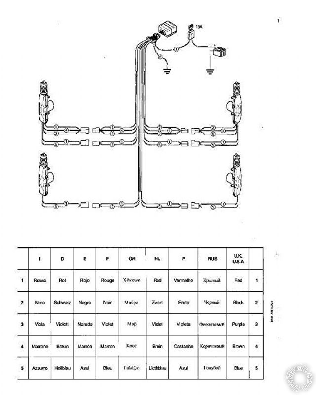
This system does not have relays it is just like the photo attached, the switches are attached inline to the brown & purple wires, in this harness, all of the wires respectively go to the same module. Ie . All browns are connected , all purples are connected. Does this mean i will need to wire install relays? Still confused.
Thanks 
Posted By: Ween
Date Posted: July 28, 2013 at 8:16 AM
the relays are in the control box/module at the top of the picture.
if the actuators you have have five wires, you should be able to disconnect the three position connectors at each and wire your switches in there. those three wires lead to a switch in the actuator to allow central locking by the front doors.
Posted By: jr789
Date Posted: July 28, 2013 at 1:55 PM
Still a little confused , as stated earlier each switch is wired in line of the three wire part of the harness. As it is by design the system is made to have only a master switch for the driver but i would like the passenger to be able to lock and unlock their side without it effecting the master on the drivers side while the master still being able to override the passengers.
Note: in my situation there are only two actuators.
Can someone if possible draw it out? Still confused.
Thanks for everyone's help
Posted By: the12volt
Date Posted: July 29, 2013 at 10:00 AM
jr789, this will do what you described. Please pay attention to the direction of the diodes in this diagram (cathode sides toward driver's side switch outputs).
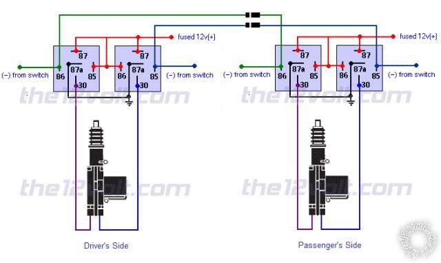
------------- the12volt Support the12volt.com
Posted By: jr789
Date Posted: July 30, 2013 at 10:03 PM
Thanks 12volt. Does this change how the diodes need to be wired? 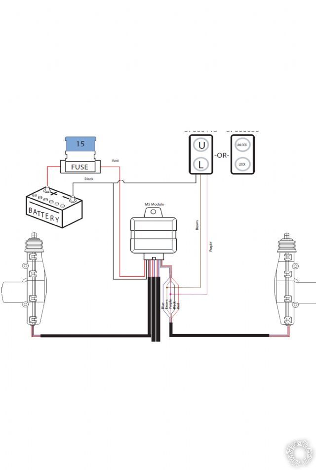
Posted By: the12volt
Date Posted: July 31, 2013 at 8:35 AM
In order to control the actuators as you described, you will need to wire everything as shown in my last diagram using four SPDT relays and two 1 amp diodes. The relay module that came with your kit will not be used. Only two wires from each actuator will be used. ------------- the12volt Support the12volt.com
Posted By: jr789
Date Posted: July 31, 2013 at 7:15 PM
Ok Thanks 12 volt , i get it , guess I'll stay with the existing setup.But you have shed some light on this mystery.
One more question with the existing system can a remote door lock system be added? Will there be any specific problems i may run into on this type of system opposed to a factory setup? And is there a recommended remote lock system?
Thanks again for your help 
Posted By: the12volt
Date Posted: July 31, 2013 at 8:54 PM
You're welcome jr789. If you connect it all as shown in the last diagram you posted, it will be very easy to add a remote door lock system (keyless entry) by tapping into the brown and purple leads coming from the switch. Any reputable brand unit will work just fine. ------------- the12volt Support the12volt.com
Posted By: jr789
Date Posted: July 31, 2013 at 9:03 PM
Many Thanks again and most appreciated !!! 
Posted By: jr789
Date Posted: September 21, 2013 at 11:17 PM
As a follow up on the installation of the spal power door locks, i purchased a Viper 211HV key-less entry unit. Everything is for the most part understandable but the five wires that operate the door locks do not make sense, im using the spal module with one centralized switch. Can anyone clue me in what needs to go where??? https://www.the12volt.com/installbay/forum_posts.asp~TID~134606~PN~1~TPN~1#680934
Posted By: jr789
Date Posted: September 22, 2013 at 12:38 PM
Now after a lot of gibberish. How about some technical help relating to the post??
|