remote start, 2010 toyota matrix
Printed From: the12volt.com
Forum Name: Car Security and Convenience
Forum Discription: Car Alarms, Keyless Entries, Remote Starters, Immobilizer Bypasses, Sensors, Door Locks, Window Modules, Heated Mirrors, Heated Seats, etc.
URL: https://www.the12volt.com/installbay/forum_posts.asp?tid=134773
Printed Date: April 29, 2026 at 9:49 AM
Topic: remote start, 2010 toyota matrix
Posted By: mike31
Subject: remote start, 2010 toyota matrix
Date Posted: August 22, 2013 at 8:52 AM
hi everyone
I am planning to remove dashboard on Toyota matrix 2010 for remote starter installation , how this is done. Thanking you all
Replies:
Posted By: racerjames76
Date Posted: August 22, 2013 at 9:31 AM
If it is like the older 06-07 I would bet most of us would give you the answer of not removing it. Remove the steering column cover and securely zip tie/tape the new wires in a bundle along with the factory wires and just feed them up from the bottom. Paying attention to how the steering column tilts/extends in and out as to not cause a pinching hazard or limiting the movement in any way. May require lengthening all of the wires to bring the unit out behind the fuse box ebrake area.
Plan ahead before completing the bench prep process! ------------- To master and control electricity is perfection. *evil laugh*
Posted By: mike31
Date Posted: August 22, 2013 at 10:51 AM
Great and thank you for the reply.I have had a look at under steering wheel if the covers are secured with screw or just click in.So I have not started anything yet.My Matrix 2010 has keyless entry and I am going to install Prostart CT3310 which is capable of remote start and keyless entry feature but I am going to install only remote start feature (only for winter season).
I have installed the same type on Cavalier 2005 and toyota rav and both cars without keyless entry from the factory and I have a question in regards to install this unit on Matrix (keyless entry from factory) would it cause anything to malfunction and I am going to buy Idatalink bypass module only for remote start.I did not have any problem with previous installation.I thank you so much for any advice.
Mike
Posted By: racerjames76
Date Posted: August 22, 2013 at 4:35 PM
More than likely your factory keyless does not operate while the engine is running. You can test this by starting the car and trying to use the factory fob. You can easily control the door locks via the new key fob via the Black lock/arm and Pink unlock/disarm in the drivers kick panel white 18 pin plug pin 7 and 6 respectively.
-------------
To master and control electricity is perfection. *evil laugh*
Posted By: mike31
Date Posted: August 23, 2013 at 10:26 AM
HI
I have changed my mind ,I will buy ADS-ALCA with remote start and keyless entry feature .I am sure I will have some questions and I am sure you guys will be great help.Thank you all
Posted By: mike31
Date Posted: August 24, 2013 at 6:43 AM
HI
Can somebody please tell me that why there are two ignition and two starter wire on Matrix 2010. my remote starter is PROSTART CT-3310 which comes without second (ignition,starter) wires. Thank you
Posted By: Chris Luongo
Date Posted: August 24, 2013 at 7:09 AM
Mike,
Why Toyota (or any other automaker) builds a car with multimple ignition and/or starter wires.....well, you'd have to find and ask a Toyota engineer; none of us would know.
Anyway, the Matrix only has one starter output coming from the ignition switch. If you look closely at the connector, it's just two wires coming out of the same connector pin. Just splice onto either wire; it doesn't make a difference since they're both going to the same place at the switch.
As for the second ignition wire....I'm not familiar with Prostart, but I can't imagine any decent, name-brand remote starter not having two ignition outputs these days. I would re-read the installation guide to make sure. In any event, even if it only has one ignition output, the installation manual should include a diagram to use a relay to configure an extra ignition output.
TIP: If you haven't noticed yet, the wiring in the Matrix is very thin and brittle, and will easily break when using a wire stripper. To get around this, just heat each wire slightly with the flame from a cigarette lighter before trying to strip it.
Posted By: mike31
Date Posted: August 24, 2013 at 8:17 AM
Thanks for the great tip. I will be back with more question as I am reading the Prostart manual.
Posted By: mike31
Date Posted: August 24, 2013 at 2:43 PM
Hi
after some search on internet I have to use two relays one for 2nd starter and other one for 2nd ignition in addition there is also a 5th realy on main harness of the R/S which can be used for 2nd ignition or 2nd starter or 2nd accessories. I wonder I can use this output (5th relay)and substitute it for one of the 2nd ignition or starter wire.Thanks a lot
Posted By: kreg357
Date Posted: August 24, 2013 at 4:44 PM
Yes, that is exactly what the "5th Relay" is for. You can set it for either IGN2 or Starter2 and use it for that wire
in the Matrix's ignition harness. That will still leave one ignition wire un-powered. The ProStart 3310 does not
make things easy for you to add a relay to support that 5th ignition wire. See the bottom of Page 20 in the CT3310
Install guide for an example or the extra relay wiring ***.
*** This circuit uses the GWR wire that might be needed for the ADS
AL CA bypass module...
Also note that the required ADS AL CA firmware depends on which transponder key your Matrix has. Either 40 Bit
(TL1) or 80 Bit "G" key (TL4).
-------------
Soldering is fun!
Posted By: mike31
Date Posted: August 24, 2013 at 11:26 PM
I have bought Idatalink interface module ADS-AL CA IS A COMBO UNIT FOR BYPASS AND KEYLESS ENTRY to be used on Matrix 2010 without G key. I have read the manual and on page 8 of 13 the wiring diagram of idatalink ADS-ALDL and it is not clear which wires I have to connect.what are the dotted black line and red solid lines means and what is data mode 1 and 2 (way).My installation will be hard wired. I am certain that all solid black lines need to be connected, what about the data mode cable .Highly appreciated
Posted By: Chris Luongo
Date Posted: August 25, 2013 at 7:00 AM
Mike,
I tried to find an online installation guide for that Prostart but I couldn't. Shame on Canadian Tire for not posting this important information.
Anyway, I repeat, the Matrix does not have two starter wires. You'll be fine.
There's a 6-pin connector at the ignition switch. Two constants, two ignitions, one starter, one accessory. The accessory just powers the radio...I intentionally don't connect this, so the radio stays off during remote start.
So all you'll do is:
R/s ignition: ignition 1 in car
R/s starter: Starter in car
R/s accessory: accessory in car (optional, your choice to connect or not)
R/s extra configurable output: configure as ignition 2, connect to other ignition wire in car.
(Sorry if text looks messy, trying to type on tablet computer.)
Also, did you verify which transponder your car has before buying module? The module is easy to reprogram with the proper cable, but ADS doesn't support DIY installers, so even if you buy the cable you'll have a hard time reprogramming. Check if your key has a dot or a G on the blade.
Dotted lines, etc: if you were to use the data cable with a compatible remote starter, the dotted lines would all be unnecessary; the data would transmit those things for you. In your case (you said hardwire), you'll discard the data cable, use the RED / BLACK/ blue-white cable, and connect the solid AND dotted wires to the remote starter.
Posted By: mike31
Date Posted: August 25, 2013 at 1:18 PM
Thank you Chris for your detailed explanation.
Hopefully I will start next week, as you have noticed I am just doing preparation. Mike
Posted By: mike31
Date Posted: August 27, 2013 at 7:13 PM
HI
I am here with more questions:
1- Can I disconnect the negative side of the battery .What is the effect on air bag and car audio system.
2- Since my remote start comes with keyless entry feature then I would connect lock and unlock wire to R/S then what about door trigger.
Thanks Mike
Posted By: mike31
Date Posted: August 31, 2013 at 9:32 PM
HI everyone
Toyota Matrix 2010 has two parking light wires one positive and the other one is negative.My remote system consist of Prostart CT-3310 and interface module Idatalink model ADS-ALCA (remote start and keyless entry combo unit).Based on Idatalink install guide ADS-AL(DL)-TL1-EN for this interface (page 6 of 13) is required to connect negative parking light wire to pin 18 of the connector at the parking light switch.There are two parking light wire from the R/S one is positive with 15 A fuse and the other one negative which is thin wire without fuse. I am rather confused here what to do, as prostart states that only one of the two parking light wire from R/S should be used not both.Do I have to use the positive output from the R/S and use a relay to provide negative pulse to pin 18 for Idatalink interface.Thanks a lot Mike
Posted By: kreg357
Date Posted: September 01, 2013 at 4:40 AM
Hi Mike,
1. Yes, you can disconnect the vehicles battery. This shouldn't present any problems to the Matrix as this
is a normal procedure if and when the battery needs to be replaced. You will probably loose all your radio
station pre-sets and the clock's time. There should be no need to disconnect any ( typically Yellow ) airbag
connectors during the install. However, most R/S installers will actually perform the entire install with the
battery connected. The only connector I disconnect during an install is the main ignition harness if it makes
soldering the wire connections easier.
2. There is a difference between the door lock wires and the door trigger wires. The lock wires operate the
door lock solenoids and the door trigger wires show the status of the doors, opened or closed. Your CT-3310
R/S w/keyless entry system has no need for door trigger inputs from the car. For your install, connect as below :
Power Lock Purple (-) @ driver kick, white 18 pin plug, pin 16 CT-3310 Pin 2 Brown
Power Unlock Beige (-) @ driver kick, white 18 pin plug, pin 15 CT-3310 Pin 3 Green
As for the Parking Lights, the wire guides list both (+) and (-) wires in the car. Your CT-3310 system has outputs
for both, some remote start systems only have one output, usually (+) or on some models it is selectable with
a jumper. For your install, you will only connect one of these outputs to the car. While the iDatalink install guide
shows the (-) Parking Light wire ( which is easy to locate & use and draws less current thru the CT-3310 ) you
could use the (+) Parking Light wire if you wished. The CT-3310 (-) Parking Light output wire, Pin 9 Orange wire,
can be directly connected to the Matrix's Brown wire at Pin 18 of the Headlight connector.
Kreg
-------------
Soldering is fun!
Posted By: mike31
Date Posted: September 01, 2013 at 10:23 PM
HI KREG
Thanking you very much for the well detailed description to my answers.
The last topic (PARKING LIGHT OUTPUT)that I am still confused. Well let me start again:
Refer to CT-3310 installation guide page 6 at the middle of the page item # 5 (YELLOW +12v PARKING LIGHT OUTPUT) it clearly states that :only one of these two different outputs needs to be connected and obviously no problem to connect either of them but as far as IDATALINK requirement is to connect negative parking light output from R/S to pin# 18, the only confusion arises here why pin#5 +12v parking lights output from R/S is heavy gauge wire with 15A fuse where as -ve output from R/S is thin wire without fuse.I hope I have explained myself clearly. Thanks a lot Mike
Posted By: kreg357
Date Posted: September 02, 2013 at 5:42 AM
Your explanation is fine, mine might have been vague. The CT-3310 is like most R/S systems on the market
currently. It is designed to support a wide variety of vehicles. Older vehicles ( like Fords with their Brown (+)
Parking Light wire at the headlight switch ) needed a high current (+) signal to actuate the parking lights. Your
CT-3310 thick gauge Yellow Parking Light output wire with the 15A fuse is designed for this style vehicle. Most
newer cars have switched to a simpler method of turning on the parking lights using low current (-) signals. The
Matrix''s Brown wire at the headlight switch connector is like this. The low current (-) output from the CT-3310's
Orange wire will handle this circuit with no issues.
While I'm not 100% positive, the Parking Light connection on the install diagram from iDatalink is a recommendation.
Being as the bypass module has no part in control or monitoring the condition of the Parking Lights, where and
how you turn then on shouldn't matter. Personally, I prefer using the low current wire and find it easy to include
another wire in the bundle already going to the steering column.
-------------
Soldering is fun!
Posted By: mike31
Date Posted: September 02, 2013 at 12:18 PM
KREG
Once again thank you so much for your response.
Now I understand what is going on. Mike
Posted By: mike31
Date Posted: September 06, 2013 at 9:21 AM
HI
I just noticed that my remote start does have data cable feature so I have to do the HARDWIRED MODE. To refresh your memory I have PROSTART CT-3310 with interface module IDATALINK ADS-ALCA for Toyota Matrix 2010.
Looking at the manual of idatalink page 6 of 13:
1- tach output, lock and unlock, brake input, from R/S to interface does it also need to be connected to the car wiring or just from R/S to interface module. Mike
Posted By: kreg357
Date Posted: September 06, 2013 at 10:56 AM
OK. ADS AL CA flashed with ADS AL(DL)-TL1 firmware, using guide #10731 and diagram on Page 6.
The answer to your question above is no.
A few points to mention.
1. If you will be connecting the bypass module to the CT-3310 remote start unit in the W2W mode, you must
set the ADS AL CA module to the Install type = Standard setting ( two LED blinks ) and lock it in prior to
programming the module to the vehicle. I usually just do a Factory Reset, set Install Mode and program
to the vehicle all at once, in that order. These steps are listed on Page 13 and Page 11.
2. In W2W mode, you will follow the iDatalink install guide diagram on Page 6. You will make all the necessary
wire connections between the two modules ( solid Black lines, solid Red lines and dashed Black lines ).
Necessary refers to the fact that while shown, the Matrix does not have a trunk release, nor a Factory
Hood Pin ( install the CT-3310 supplied hood pin). Additionally, the CT-3310 has no need for the Door Status,
E-Brake or Trunk Status signals.
3. In W2W mode you will not use the ADS AL CA supplied D2D harness. Instead use the Black 4 pin connector
harness that has three wires, Red, Black and Blue/White. These wires go to the CT-3310, +12V power,
chassis ground and Ground When Running ( aka (-) Status Output ).
4. The ADS AL CA Pink wire gets connected to the CT3310 thick Ignition1 wire that continues to the Matrix's
Ignition 1 wire.
5. The bypass module does supply a nice Tach Signal, so use that and run in Tach Mode for good reliability.
Any signal supplied by or handled by the bypass module does not have to be redundantly connected to the
Matrix. This includes the Lock/Arm, Unlock/Disarm, Tach and Brake signals for your R/S w/keyless install.
The ADS bypass module does this thru the CAN data connections.
-------------
Soldering is fun!
Posted By: mike31
Date Posted: September 06, 2013 at 7:45 PM
HI Kreg
Thakn a lot for your response ,no doubt this is a great site with great and helpful people.
I am trying to locate the immobilizer on Matrix 2010 , it is a black connector with only 4 wires: violent,beige (light pink), light blue, green . It is located at the end of the ignition key assembly and it is supposed to be 7 pin connector which I can not see clearly. I wonder somebody can verify it if it is the one that I am seeing. Thanks Mike
Posted By: kreg357
Date Posted: September 06, 2013 at 8:27 PM
Here is a photo of the transponder wires from the 2009 Vibe Pictorial :
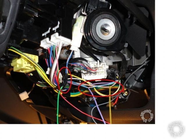 ------------- Soldering is fun!
Posted By: mike31
Date Posted: September 06, 2013 at 11:46 PM
HI
Is ASD-ALCA needs to be fused and if so what should be ampere .
Thank you. Mike
Posted By: kreg357
Date Posted: September 07, 2013 at 6:40 AM
Personally, I never add a fuse to the thin ADS AL CA Red +12V power input wire. If you feel the need, a 3 Amp fuse would be my guess.
-------------
Soldering is fun!
Posted By: mike31
Date Posted: September 10, 2013 at 11:07 PM
HI
How do I do programming the 4 button transmitter and R/S itself. Now wiring is different .
Thanks a lot. Mike
Posted By: mike31
Date Posted: September 10, 2013 at 11:32 PM
I reviewed the Prostart manual and PAB can be used instead of the hood pin switch as long as hood is up (page 10) and follow the rest of the procedure ,but at the same time the hood pin switch is not connected to R/S but to ASD-ALCA ORANGE / black wire as (-) input.
I am not really sure if it works.Mike
Posted By: kreg357
Date Posted: September 11, 2013 at 6:25 AM
I am a bit confused. It seems your connections concerning the Hood Pin Switch are wrong.
Here is the way it works ( the long story ).
On vehicles that have a Factory Hood Pin Switch installed, the ADS AL CA with DL TL1 firmware will obtain
the hood pin info from the vehicle via the CAN Bus data connection and supply that information to the R/S
( CT-3310 in your case ) through the Yellow wire ( shown as a Red line in the install diagram ). If the vehicle
does not have a Factory Hood Pin Switch, the AD AL CA ORANGE / Black wire must be grounded and the Yellow
wire won't used / connected because it is not able to supply any Hood Pin Status Info. In this case, a after-
market hood pin switch should be installed and it's signal wire directly connected to the R/S ( CT-3310 for you ).
The short story :
Your vehicle did not come with a Factory Hood Pin Switch ( I'm assuming you checked ).
The ADS AL CA w/DL TL1 firmware is not able to supply a Hood Status Output.
The ADS AL CA ORANGE / Black wire is connected to Chassis Ground.
The ADS AL CA Yellow wire is not used / connected.
An after-market hood pin switch will be installed in the car. It's signal wire will be connected directly to the
CT-3310 5-Pin Secondary Harness, Pin 3, Grey wire.
With the Hood Pin Switch installed and connected directly to the CT-3310, you should have no problems
programming the remotes and setting the other programming options using either the hood pin switch
or the PAB ( with the hood up ).
-------------
Soldering is fun!
Posted By: mike31
Date Posted: September 11, 2013 at 8:51 AM
HI
Thank you Kreg for clarification.I thought hood pin switch is connected directly to ORANGE / black wire.Looking at page 6 of the Idatalink wiring diagram(type one)shows no direct connection from R/S to hood pin switch in compare to parking light connection. Mike
Posted By: mike31
Date Posted: September 13, 2013 at 1:25 AM
Hoping to be my final question
system : Prostart CT-3310 remote starter, Idatalink (ASD-AL CA),Toyota Matrix 2010
HI
I have prepared R/S and ASD-AL CA to be connected to Matrix wiring system . I am certain that only ignition wire #1 (brown to pink wire of the ASD-AL CA to ignition wire of R/S) and starter wire #1 (black)to R/S, but what about ignition wire #2, starter #2.
I think they are NOT required to be connected to any external circuit
Please advice
Thank you . Mike
Posted By: kreg357
Date Posted: September 13, 2013 at 5:47 PM
The ADS AL CA w/TL1 install guide does not show all necessary connections from the R/S, only for the bypass.
The TL1 install diagram does have this note coming off the top of the generic R/S :
"STANDARD (IGN, ACC, START) REMOTE STARTER
CONNECTIONS TO VEHICLE ARE REQUIRED"
As Chris explained earlier, you must test the Matrix's main ignition connector and make all of the necessary connections.
At a minimum there will be 2 Ignition wires, one Starter wire and one Accessory wire. This list includes the wire that you
already mentioned that has the ADS AL CA Pink wire attached.
-------------
Soldering is fun!
Posted By: mike31
Date Posted: September 14, 2013 at 4:35 PM
HI EVERYONE
Just for your info I have checked with 3 other remote starter websites plus 12volts.com and Matrix 2010 2.4L engine comes with second starter wire at ignition switch:
TOYOTA
MODEL YEAR(S)
MATRIX 2009 -2010
KEY T-HARNESS IMMOBILIZER
N/A N/A TOYOTA'S TRANSPONDER SYSTEM, Requires Bypass Module, See NOTE #1
PART COLOR LOCATION
12 VOLT CONSTANT WHITE (+) 120 AMP @ DASH FUSE BOX, (WHITE, 1-Pin Plug(G) Pin 1
STARTER BLACK (+) @ IGNITION SWITCH, (WHITE, 8-Pin Plug) Pin 8
STARTER 2 WHITE (+) (2.4L Engine Only!) @ IGNITION SWITCH, (WHITE, 8-Pin Plug) Pin 1
IGNITION 1 BROWN (+)@ IGNITION SWITCH, (WHITE, 8-Pin Plug) Pin 6
IGNITION 2 GREEN (+)@ IGNITION SWITCH, (WHITE, 8-Pin Plug) Pin 4
Thanks Mike.
Posted By: kreg357
Date Posted: September 14, 2013 at 6:16 PM
I don't remember seeing any info on which engine your Matrix had but that is why I said "at a minimum"
in my last post.
Once you get the steering column open, you can use your DMM to test and verify that wire guide
information. As I mentioned in another previous post, the CT-3310 can handle 4 of the ( possibly ) 5
ignition wires. If you do indeed have the Starter2 wire, you must power it with a separate external
relay to keep it isolated. The CT-3310 install guide has the relay wiring diagram on Page 20.
-------------
Soldering is fun!
Posted By: mike31
Date Posted: September 14, 2013 at 7:32 PM
Thanks for the reply, as you did guide me I have already wired up an external relay for the second ignition wire and fifth relay for the second starter wire. I will identify both starter and ignition wires
( 1& 2) using digital meter prior to connection.
Thanks again. Mike
Posted By: mike31
Date Posted: September 15, 2013 at 5:15 PM
HI
I put the R/S plus ASD-AL CA interface together after programming R/S transmitter and interface. I have a main problem and that is when car started by remote engine keep cranking and during this time the engine trouble comes on naturally I shut off the engine by remote.I have double checked my wiring and looks OK .Just as info I have checked both ignition wires (1 & 2) with DMM and ignition wire #2 signal is done by and automotive 24v dc with a diode and connected as:
85 ignition #1
86 GWR
87 12v constant
30 to ignition wire #2
I have programmed the interface using Idatalink manual for WTW , remote start keyless entry works great.I have also checked both tach wires from ASD-AL CA to remote and it is OK. I do not really know what is wrong here.
Thanks for advice . Mike
Posted By: kreg357
Date Posted: September 15, 2013 at 6:05 PM
Probably some dumb questions but... ( there are a bunch of possibilities )
Are you sure the ADS AL CA has the DL TL1 firmware?
Verify your ignition key is a 40 bit key ( without the "G" stamp).
Did you set the ADS AL CA to Standard Mode ( two blinks ) prior to actual vehicle programming?
Did the ADS AL CA follow the vehicle programming responses exactly?
During a remote start does the ADS AL CA LED flash Green?
Are you sharing the GWR signal between the extra relay and the bypass module?
Any Security type lights on the instrument panel?
What happens if you insert a key into the ignition cylinder and try a remote start? ( might have to unplug
the power harness to the ADS AL CA )
Have you tried doing a CT-3310 TACH re-learn?
-------------
Soldering is fun!
Posted By: mike31
Date Posted: September 15, 2013 at 7:40 PM
HI Kreg
I am not sure how to know about the firmware but I asked the seller if this unit is loaded with latest firmware for toyota matrix 2010 and he said" yes ".
Car key has only one dot stamped on it not G (the Idatalink seller also checked my car key just to be sure prior to purchase the unit.
I had few programming attempt till I had it right however I will try to do factory reset again before re-programming.
Yes set to standard mode (two flash)
I have not checked green led during remote start.
yes GWR is shared.
The only light is engine trouble and it turns off when remote is shut down.
I have not tried with key insertion yet.
No I have not done the Tach re-learn.Waiting for your response
Thank you Mike
Posted By: kreg357
Date Posted: September 15, 2013 at 8:30 PM
If the iDatalink seller checked the key for a "G" or "." then you should be good and have the TL1 F/W.
Sounds like you did all the bypass programming correctly. A Factory Reset and re-program can't hurt. Also
a reset and Tach learn on the R/S unit can't hurt either.
The ADS install guide has a LED indication guide at the end to assist. The ADS AL CA should show the
flashing Green LED during a R/S if it is getting a good GWR input. If you don't get that indication, try separating
the ADS GWR wire from the relay and jumping it directly to chassis ground when you initiate a R/S.
The other test would be unplugging the ADS AL CA power harness and placing an ignition key in the
cylinder ( not turned ) and then try a R/S.
You can also put the DMM on the IGN1 and IGN2 output wires and verify +12V during a R/S.
Did your pre-install testing verify all ignition wires? IGN1, IGN2, Starter1, Starter2, Accessory1
Was there a Starter2 wire?
Did you separately power all ignition wires?
-------------
Soldering is fun!
Posted By: mike31
Date Posted: September 15, 2013 at 8:56 PM
HI Kreg Latest update
I just inserted the key into the ignition switch and remote starter works fine but I did not unplug the power from the ASD-ALCA.
I removed the key and checked green LED on the ASD-ALCA while remote starting ,as before keep cranking and LED being OFF.
I followed the procedure (auto tach programming)Page 12 of Installation Guide CT-3310 table 4 but remote start did not respond at all.
As adviced I will provide direct ground to 86 of the coil.I will be back . Mike
Posted By: kreg357
Date Posted: September 15, 2013 at 9:08 PM
Actually leave the relay alone, you need it for the ignition circuit. Just disconnect the ADS GWR wire from that circuit ( pin 86 ) and jump the ADS GWR wire to chassis ground at the beginning of a R/S.
-------------
Soldering is fun!
Posted By: mike31
Date Posted: September 15, 2013 at 9:54 PM
HI
Thank you very much for the help I will continue with it tomorrow morning . Mike
Posted By: mike31
Date Posted: September 15, 2013 at 10:19 PM
HI
As mentioned I removed the GWR wire from the circuit (ADS unit blue/white) and was connected direct to chasis ground and I am having the same problem. I will continue to work with car tomorrow morning. Mike
Posted By: mike31
Date Posted: September 15, 2013 at 11:34 PM
HI
In regards to ignition and starter wires , yes I did use DMM and verified, there are two starter and two ignition wires and all 4 wires are connected separately.Mike
Posted By: mike31
Date Posted: September 16, 2013 at 11:32 AM
HI AGAIN
I called the Idatalink support and problem I have is due to the fact that my R/S does not give ground output while starting by remote.I did verify this by touching the GWR wire to car chassis ground while starting by remote and everything worked fine. I am thinking to use one relay to give ground output to R/S and ASD-AL CA unit as GWR input. Starter wire(Ignition switch) as +ve to the coil of the relay.Any advice
Thanks Mike
Posted By: kreg357
Date Posted: September 16, 2013 at 12:12 PM
On the CT-3310, the White wire at Pin 10 of the 12 Pin plug is (-) Ground out When Running. Unless there
is something wrong with the unit itself, you should be able to use this wire. The problem could be using
it for both the Ignition 2 relay and the ADS bypass module GWR input at the same time ( sharing ).
If the CT-3310 is OK, here is one way to ensure proper signals to both the IGN2 relay and the ADS bypass.
Obtain another 30/40 Amp relay. Wire as follows :
All of the current Ignition2 relay wiring is working, so leave it alone. This is from your earlier post.
Pin 85 to ignition #1 output from CT-3310 ( which also goes to vehicle IGN1 wire )
Pin 86 to CT-3310 GWR White wire Pin 10 on 12 Pin plug
Pin 87 12v to +12V constant thru fuse
Pin 30 to Matrix Ignition wire #2
Extra relay :
Pin 85 to CT-3310 GWR White wire Pin 10 on 12 Pin plug
Pin 86 to +12V constant ( thru 2 Amp fuse if you want )
Pin 87 to Chassis Ground
Pin 30 to ADS AL CA Blue/White GWR wire
The CT-3310 White GWR wire is rated at 500mA, so running two relays with it is no problem.
The second relay will ensure a solid ground GWR signal to the ADS bypass module.
-------------
Soldering is fun!
Posted By: mike31
Date Posted: September 16, 2013 at 11:48 PM
HI
Sorry if I did not reply to your post earlier on as I was at work till late. Without any doubt the R/S unit is OK otherwise engine would not
start by R/S when the blue/white wire of the ASD-AL CA was briefly touched to chassis ground and as mentioned before ignition wire #2 signal comes from the relay that -ve side of the coil is connected to GWR of the R/S. Tomorrow if time allows, I will wire up the extra relay according to your instruction and final results will be posted.
Thanks for the info. Mike
Posted By: mike31
Date Posted: September 18, 2013 at 8:26 AM
HI
Second relay connected and found that all lights comes on without even ignition key inserted into the ignition cylinder, I was really surprised >Checked wiring OK, disconnected GWR from second relay then lights went off.I connected back the GWR wire to second relay and removed both R/S and ASD-AL CA from the car wiring and still lights on
I also checked with DMM set to OHMS form chassis ground to GWR wire (white) with reading of about 0.399 Kohms indicating no short between GWR wire and chassis ground. Any advice MIke
Posted By: kreg357
Date Posted: September 18, 2013 at 8:50 AM
OK, your CT-3310 is not going to make this easy ( as mentioned on Page 1 ). The way the IGN2 relay is
wired, the Pin 85 input must be at chassis ground when OFF, not a float.
To set this up correctly so that you can get a clean GWR output from the CT-3310 for the ADS AL CA,
you must keep things completely separate. So...
Connect the CT-3310 GWR wire to the ADS AL CA GWR wire directly. This will be its' only connection. It will
not be used by or connected to the relays at all.
The two relay will be re-wired and renamed as below :
Relay 1 for IGN1
Relay Pin 85 to Chassis ground
Relay Pin 86 to CT-3310 Ignition1 output
Relay Pin 87 to +12V constant thru 20 Amp fuse
Relay Pin 30 to Matrix Ignition1 wire
Relay 2 for IGN2
Relay Pin 85 to Chassis ground
Relay Pin 86 to CT-3310 Ignition1 output
Relay Pin 87 to +12V constant thru 20 Amp fuse
Relay Pin 30 to Matrix Ignition2 wire
-------------
Soldering is fun!
Posted By: mike31
Date Posted: September 18, 2013 at 11:06 AM
HI Kreg
Thanking you for the reply. Ignition #1 already connected to CT-3310 R/S ignition output Yellow heavy gauge wire I wonder if can I tap from this yellow wire to a relay :
85 12 v yellow wire ignition output from the R/S
86 chassis ground.
87 12v constant.
30 ignition #2.
and as you suggested direct connection from R/S GWR wire to ASD AL CA .
Mike
Posted By: kreg357
Date Posted: September 18, 2013 at 1:29 PM
You can try that way but...
Wired that way, the relay will also energize and supply an output whenever the car is running. The relay will get the +12V on Pin 85 coming from the Matrix's Ignition1 wire, instead of the CT-3310's Ignition1 output wire, because they are tied together and electrically common.
Wired as I listed will totally isolate the CT-3310's Ignition output from the vehicle and keep the vehicles two Ignition wires isolated. The two relays will only energize and supply an output during a remote start, controlled by the CT-3310.
Figured that being as you had the extra relay, might as well put it to good use.  ------------- Soldering is fun!
Posted By: mike31
Date Posted: September 18, 2013 at 10:41 PM
HI
I will follow the wiring for relay #1 and #2 in your previous post, as you mentioned: (The two relays will only energize and supply an output during a remote start, controlled by the CT-3310).
Thanking you so much, no doubt your suggested wiring diagram for two relays is the only solution to my problem. I will rewire the system and update will be posted tomorrow. Mike
Posted By: mike31
Date Posted: September 19, 2013 at 3:10 PM
HI
I rewired two relays but still problem exist but something new and that is the ASD-AL CA can not be programmed since ignition wire is not connected to matrix wiring but to relays therefor during programming it does not see +12v at the pink wire while the key is turned to run. Mike.
Posted By: kreg357
Date Posted: September 19, 2013 at 4:04 PM
Easy enough. Just move the ADS AL CA Pink Ignition input wire to Pin 30 wire of Relay1 that goes to the Matrix Ignition1 wire.
However, just thought of another new problem. Most R/S systems rely on seeing an actual vehicle Ignition wire. Sometimes it's for the alarm, virtual tach, programming or tach learn reasons. If you run into problems, you might have to go with your single relay diagram and live with the fact that the Ignition2 relay will be on while driving.
As a point of interest, most R/S systems have extra (-)200mA outputs for Igntion2, Starter2 and Accessory2, making adding relays for this type of install so much easier.
-------------
Soldering is fun!
Posted By: mike31
Date Posted: September 20, 2013 at 12:53 AM
How about to go back to one relay for ignition #2,add a second relay to be energized by starter wire# 1 :
85 starter wire #1
86 chassis ground
87 chassis ground
30 blue/white wire of ASD-AL CA.
This way true ground signal supplied to ASD while cranking, once car started then starter is disengaged and second relay is dropped out.
Do you think this might work. Mike
Posted By: kreg357
Date Posted: September 20, 2013 at 7:21 AM
I'm getting confused. Does the CT-3310 have a problem with it's White G.W.R. output wire? That wire,
if working properly should be all that is needed to signal the ADS AL CA. You should be able to test this
wire with a DMM during a remote start attempt.
-------------
Soldering is fun!
Posted By: mike31
Date Posted: September 20, 2013 at 12:06 PM
I will test it .Thank you
Posted By: mike31
Date Posted: September 20, 2013 at 7:13 PM
Should I check for continuity between GWR wire of the R/S and ground using DMM set to ohms while remote start is running , if it is the case then no continuity . The meter reading is about 0.399 kilo ohms .Does this indicates that my R/S is gone bad or there is another kind of test. Mike
Posted By: kreg357
Date Posted: September 21, 2013 at 8:57 AM
No, use the 20V DC range. Connect the Red test lead to +12V constant and the Black Test lead to the CT-3310 White G.W.R. output. When the G.W.R. signal goes active, you will see +12V on the DMM. ( The G.W.R. signal going to (-), or chassis ground, will complete the circuit and the meter will read +12V.)
-------------
Soldering is fun!
Posted By: mike31
Date Posted: September 22, 2013 at 12:16 AM
Thanks for the info. I checked the output voltage of GWR wire and I do no get 12v dc while remote starting. I bought Prostart CT-3371 (on sale)which is slightly different than CT-3310. hopefully I will use it tomorrow (Sunday)after minor wiring change (-ve parking output wire ) plus programming change (mode 3 to change option 2 to option 1 for ADS and function 3 to change option 2 to option 1 for one way com). I think the rest of the default option are fine for auto transmission.
Just to remind you that I will use only one relay for second ignition wire and sharing GWR wire with this relay as well as ASD.
Since I am using fifth relay for second starter wire do I need to connect it to a relay or direct connection from fifth relay output to second starter wire. MIKE
Posted By: kreg357
Date Posted: September 22, 2013 at 7:19 AM
The fifth relay output can be directly connected to the vehicles Starter2 wire.
Good luck with the new unit.
-------------
Soldering is fun!
Posted By: mike31
Date Posted: September 23, 2013 at 5:27 PM
HI
Finally success with Prostart CT-3371. I used only one relay for the second ignition wire which was not energizing during remote start because it was connected to GWR plus shared with ADS . I also checked the voltage at the GWR not even 1 volt dc ,so I connected GWR to ADS directly and used chassis ground for for the relay . Now everything works beautiful except that to unlock all doors I have to hold on to unlock button of the remote for a few seconds to open all doors in compare to toyota key with only two short clicks.I am just wondering if my CT-3310 unit is not defective after all or perhaps I should used an isolation relay but I am not sure how however Prosart manual emphasize to use an isolation diode whenever GWR is used.
Just for your info no programming change was carried out since my system is WTW (Prostart tech support).Once again Thank you for all the support ,I did learn a lot and enjoyed every minute of it.Mike
The following paragraph from prostart installation manual in regards to GWR:
WHITE () Ground out when running:
CAUTION! If multiple relays or modules are connected to the Ground
Out wire, ensure that they are all diode isolated in order to avoid
feedback and damaging the vehicle.
|