Hi

Hope someone can help me out with this. I have a 1988 F150 2door. I have installed a Spal aftermarket door locking system. It is wired so that the spal control module is the relay for the system. I would like to wire up the viper module to work with this centralized system rather than wiring in relays for each actuator.
What needs to go where in regards to main 12 pin harness connections on the viper module (ie lock/unlock 30 lock/ unlock 87 wires??
P.S. here is a basic wiring diagram of the spal system
Spal diagram
Thanks for your help

Most everything works as it should ,except the horn however will not activate with the remote, i tapped into the correct wire and also checked with a volt meter to be for sure. Will another relay or some extra wiring be needed? I'm happy with the remote and door locks as well as the parking lights flashing but it sure would be nice to get the benefit of the horn. Thanks
That's good news so far. Interesting with the horn. I have always used the straight (-) 200mA Horn output
wire from the after-market system directly attached to the Dark Blue Ford horn wire with no issues. A few
possibilities here.
You could check the 211HV's Horn output to verify it is indeed working. Easiest way is with a LED test light
but a DMM will work also. Set the DMM to 20V DC, Red test lead to a +12V constant source and Black test
lead to the 211 HV H1/12 Brown wire. The DMM will go to +12V when the system tries to beep the horn. You
can use the same DMM set up on the truck's Dark Blue Horn wire. Every time you press the horn button, the
DMM should read +12V ( and the horn will sound ). As a final test, you can use a jumper wire from chassis
ground to briefly touch the Dark Blue horn wire. That should also beep the horn.
-------------
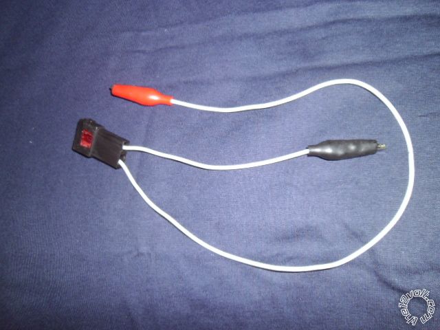
Soldering is fun!
Thanks again Kreg!!! Ill give it a try later this week and post.

kreg ,
I tried the dark blue wire and it does not work: according to the schematic , there is a
yellow/ light blue & the Dark blue labeled as horn brush contactson the column harness, apparently they work together , the yellow/ light blue is a hot wire. i'm not quite sure if it is worth the effort to have the horn wired in. Perhaps the module does not send a strong enough pulse. P/S My truck , factory plain jane does not have cruse control and as a result it is not equipped with a horn relay according to the factory manual. Think i solved the problem.

Sounds logical enough.
If the test with the jumper to the Dark Blue (-) Horn wire works, you could try adding a relay to the 211HV's Horn Output. Here is the wiring :
Relay Pin 85 to 211HV H1/12 BROWN (-) HORN HONK OUTPUT
Relay Pin 86 to +12V Constant
Relay Pin 87 to Chassis Ground
Relay Pin 30 to F150 Dark Blue Horn wire
Relay Pin 87a not used - insulate
( More soldering fun...

)
-------------
Soldering is fun!