scytek sp 400
Printed From: the12volt.com
Forum Name: Car Security and Convenience
Forum Discription: Car Alarms, Keyless Entries, Remote Starters, Immobilizer Bypasses, Sensors, Door Locks, Window Modules, Heated Mirrors, Heated Seats, etc.
URL: https://www.the12volt.com/installbay/forum_posts.asp?tid=134963
Printed Date: April 10, 2026 at 2:20 PM
Topic: scytek sp 400
Posted By: davanthony
Subject: scytek sp 400
Date Posted: September 28, 2013 at 6:22 PM
i recently installed the scytek sp400, because it was cost effective however i installed it following the diagram that came with it and the wiring diagram for my 88 camry and the alarm does nothing when you try to arm or disarm it. the panic mode works so i know it is getting power and signal from the remote any help anyone can give would be nice
thanks
Replies:
Posted By: kreg357
Date Posted: September 28, 2013 at 6:53 PM
Help us out. Make up a wire connection list of the current wiring. The forum members can review it and make corrections and recommendations to assist you.
-------------
Soldering is fun!
Posted By: davanthony
Date Posted: September 28, 2013 at 7:06 PM
1. Theres the 12v power to the batt
2. the black ground
3.(-) door trigger to the - trigger in the kick panel
4. siren output
5. parking light output 12v(+0 to the dark green parking light wire in the kick panel
6.a 12v ignition input connected it to the 12v constant in the ignition switch harness
7. the stater kill relay
8.
and the - power door lock controls for look and unlock
Posted By: kreg357
Date Posted: September 28, 2013 at 8:17 PM
Boy, that sure didn't help me. Perhaps this is what you meant to type :
CrimeStopper SP-400 ( SCYTEK SP-400 )
9 Pin Connector 1988 Camry Auto trans w/o factory alarm
Green (-) Start Activation / (-) Turbo Timer Not used
Brown (+) Siren Output Scytek siren
BROWN / White(-) Horn Output GREEN/ BLACK (-) @ STEERING COLUMN HARNESS
BLACK/ White (-) Dome Light Output RED / WHITE (-) IN DRIVERS KICK PANEL,
GREEN/ Red (-) AUX1 not used
Blue/Black (-) IGN Output / AUX2not used
Blue/White (-) Pass Door Unlocknot used
Orange (-) Starter Kill / AnitGrind Output wire relay as shown on Page 6
ORANGE / Black (-) OEM Disarm Output not used
3 Pin Connector
WHITE/ Red Tach InputBLACK (AC) @ IGNITIOR or DIAGNOSTIC PLUG,
Black Chassis Ground Chassis Ground
White Selectable Parking Light Output DARK GREEN (+) IN DRIVERS KICK PANEL ** Set to (+)
6 Pin High Current
1 Gray ACC Output PINK/BLUE (+) @ IGNITION SWITCH HARNESS
2 Brown Starter Output BLACK/ WHITE (+) @ IGNITION SWITCH HARNESS
3 Red +12V Input White @ IGNITION SWITCH HARNESS
4 Red +12V Input WHITE/ Red @ IGNITION SWITCH HARNESS
5 Pink IGN OutputBLACK / YELLOW (+) @ IGNITION SWITCH HARNESS
6 Pink/White Selectable Output ( IGN, ACC, Satrter ) BLACK/ ORANGE (+) @ IGNITION SWITCH HARNESS ***Set to IGN2
5 Pin Connector
Violet (+) Door Pin Input not used
Green (-) Door Pin Input RED / WHITE (-) IN DRIVERS KICK PANEL
Blue (-) Hood / Trunk Pin Input to supplied & installed hood pin
Pink Wait to Start or Passive Carjack Input not used
White (+) Brake Input GREEN / WHITE (+) @ SWITCH ABOVE BRAKE PEDAL
4 Pin Output Connectot
Yellow/Black (-) OEM Rearm Output not used
Blue/Orange (-) Starter not used
Violet/White (-) AUX3 not used
GREEN / WHITE (-) AUX4 not used
Door Lock Connector
1 Blue (-) Unlock OutputGREEN/ RED (TYPE B) IN EITHER KICK PANEL
2 Red +12V Output not used
3 Green (-)Lock Output LIGHT GREEN (TYPE B) IN EITHER KICK PANEL
-------------
Soldering is fun!
Posted By: davanthony
Date Posted: September 28, 2013 at 10:49 PM
Yesh that looks a little bit better then what i sent you huh, however, it looks different my pin conectro for my alarm brian is a 13 pin and it has a five pin for the door lock setup so i was a little list reading that but if i hooked up something wirng would that cause it to do nothing at all?
Posted By: kreg357
Date Posted: September 29, 2013 at 4:43 AM
That is why the OP supplying the actual plug / harness connector wiring from his actual system is so much better than trying to guess what unit / version / configuration he has. Saves a lot of time and prevents wasting time. Sorry I couldn't help ( but I sure tried ).
-------------
Soldering is fun!
Posted By: davanthony
Date Posted: September 29, 2013 at 8:13 AM
yes you did and i am very greatful for the atemped im going to scan the diagram thatcame with the system and post shortly
Posted By: davanthony
Date Posted: September 29, 2013 at 8:37 AM
Posted By: kreg357
Date Posted: September 30, 2013 at 7:10 PM
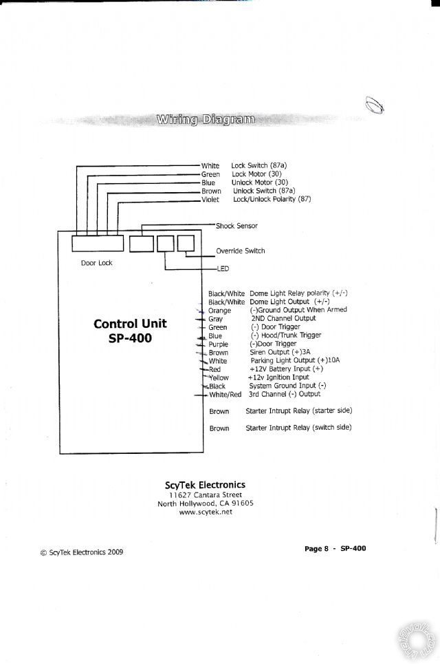
Can't find the full manual for this alarm but...
BLACK/ White Dome Light relay input Chassis Ground
BLACK/ White Dome Light Output RED / WHITE (-) IN DRIVERS KICK PANEL,
Orange (-) GWA not used
Gray (-) 2nd Channel Output not used
Green (-) Door Trigger RED / WHITE (-) IN DRIVERS KICK PANEL,
Blue (-) Hood/Trunk Trigger to supplied & installed hood pin
Purple (-) Door Trigger ??? not used ( think this is really the (+) Door Trigger )
Brown (+) Siren Out Scytek siren
White (+) Parking Light Out DARK GREEN (+) IN DRIVERS KICK PANEL
Red +12V constant White @ IGNITION SWITCH HARNESS
Yellow (+) IGN In BLACK / YELLOW (+) @ IGNITION SWITCH HARNESS
Black Chassis Ground Chassis Ground
WHITE/ Red (-) 3rd Channel Out not used
Brown Starter Int ( car side ) BLACK/ WHITE (+) @ IGNITION SWITCH HARNESS \____ cut wire
Brown Starter Int ( Switch side ) BLACK/ WHITE (+) @ IGNITION SWITCH HARNESS /
Locks
White Lock 87a not used
Green Lock 30 LIGHT GREEN (TYPE B) IN EITHER KICK PANEL
Blue Unlock 30 GREEN/ RED (TYPE B) IN EITHER KICK PANEL
Brown Unlock 87a not used
Violet Lock/Unlock Polarity ( 87 ) Chassis Ground
-------------
Soldering is fun!
Posted By: tbjoe
Date Posted: October 18, 2013 at 12:20 PM
If this hasn't been solved yet. Did you check if you have it set to silent arm/disarm or maybe valet mode? I assume that in your original post that you are talking about the siren not making noise when you lock/arm and unlock/disarm the system. Am I right?
Posted By: oscarb
Date Posted: March 21, 2014 at 2:45 PM
I have been buy an alarm with this description 3 months ago , I did not install it jet , I was busy , I inspected the central module and found visually an IC pin #2 cut it (ATMEL 739 93C46 PC ; because of this , I just send today a message to the seller if the alarm was modified .)
What ever , this alarm have a SW1 (4 ) that have to do with the properly setup (I can't find a diagram ).
|