Hey guys I just wanted to make sure all my connections looked right before I start this install.. and also would you go d2d or w2w with the XK05 bypass?
H1/1: Trunk Release - WHITE/ Green in drivers kick panel
H1/2: Constant 12V - WHITE/ Green in ignition harness
H1/3: Siren Output - Siren Red Wire (+)
H1/4: NOT USED
H1/5: Chassis Ground - factory ground in drivers kick panel
H1/6: NOT USED
H1/7: NOT USED
H1/8: Door Trigger Input: - RED / Blue at SECU pin 3 (Install Diode)
H1/9: Dome Light - RED / Black at SECU pin 31 (RELAY REQUIRED)*
H1/10: NOT USED
H1/11: Parking Light Output - Green at SECU pin 20 (Install Diode)
H1/12: NOT USED
*Dome Light Supervision relay
Pin 86: H1/9(5701) BLACK/ white
Pin 87: Dome Supervision (SECU Pin 31) RED / Black
Pin 85: Constant 12v (+)
Pin 30: Chassis Ground
H2-Did not use
H3/1: Ignition 1 Output - BLACK/ White at ignition harness
H3/2: Ignition 2 / Flex Relay - Red (Constant 12V) at ignition harness
H3/3: Accessory Output - RED / Yellow at ignition harness
H3/4: Starter Output (Starter side) - BLACK / YELLOW
H3/5: Starter Input (Key Side) - BLACK / YELLOW
H3/6: Fused Ignition 1 Input - Red (Constant 12V) at ignition harness
H3/7: Ignition 2 / Flex Relay Output - RED / Black at ignition harness(Program as Second Starter)
H3/8: NOT USED
H3/9: Fused Accessory Input - Red (Constant 12V) at ignition harness
H3/10: NOT USED
Remote Start Input Harness:
Pin 1: Neutral Safety Switch Input - Ground
Pin 1: Tachometer Input - WHITE/ Green at TCM pin 39
Pin 1: Brake Shutdown - GREEN/ YELLOW at brake pedal switch
Pin 1: Hood Pin Switch - Yellow/Black at SECU pin 6
Pin 1: Rear Defogger Output - Orange at SECU pin 14
Remote Start Auxiliary Output Harness:
Pin 1: NOT USED
Pin 2: NOT USED
Pin 3: NOT USED
Pin 4: NOT USED
Pin 5: Goes to XK05 module (brown wire from XK05)
Door Lock Harness:
Pin 1: (-) Unlock Output - Light Green at SECU pin 10
Pin 2: NOT USED
Pin 3: (-) Lock Output - Yellow at SECU pin 11
H1/1: Trunk Release (-) WHITE/ Green in drivers kick panel
Trunk (glass hatch) release is a high current (-) and will need a relay, do not connect it directly to the H1/1.
Use a diode either across the coil of the relay -or- inline on the H1/1 wire before it goes to the relay.
H1/2: Constant 12V - WHITE/ Green in ignition harness
H1/3: Siren Output - Siren Red Wire (+)
H1/4: NOT USED
H1/5: Chassis Ground - factory ground in drivers kick panel
H1/6: NOT USED
H1/7: NOT USED
H1/8: Door Trigger Input: - RED / Blue at SECU pin 3 (Install Diode)
No need for a diode here, you're only connecting to one wire that will monitor all doors.
H1/9: Dome Light - RED / Black at SECU pin 31 (RELAY REQUIRED)*
This should be a low current (-) (thin gauge wire) & no need for a relay.
H1/10: NOT USED
H1/11: Parking Light Output - Green at SECU pin 20 (Install Diode)
No diode required. Make sure to set the jumper/fuse on the viper unit to (-) park lights output.
H1/12: NOT USED
*Dome Light Supervision relay
Pin 86: H1/9(5701) BLACK/ white
Pin 87: Dome Supervision (SECU Pin 31) RED / Black
Pin 85: Constant 12v (+)
Pin 30: Chassis Ground
H2-Did not use
H3/1: Ignition 1 Output - BLACK/ White at ignition harness
H3/2: Ignition 2 / Flex Relay - Red (Constant 12V) at ignition harness
H3/3: Accessory Output - RED / Yellow at ignition harness
H3/4: Starter Output (Starter side) - BLACK / YELLOW
H3/5: Starter Input (Key Side) - BLACK / YELLOW
H3/6: Fused Ignition 1 Input - Red (Constant 12V) at ignition harness
H3/7: Ignition 2 / Flex Relay Output - RED / Black at ignition harness(Program as Second Starter)
H3/8: NOT USED
H3/9: Fused Accessory Input - Red (Constant 12V) at ignition harness
H3/10: NOT USED
Remote Start Input Harness:
Pin 1: Neutral Safety Switch Input - Ground
Pin 1: Tachometer Input - WHITE/ Green at TCM pin 39
Not sure where the TCM is but you can also find the Tach wire WHITE/ Green (ac) at the ECM to right of steering column, pin 103
Pin 1: Brake Shutdown - GREEN/ YELLOW at brake pedal switch
Brake wire can also be found at the driver's kick (harness going to the rear) GREEN / WHITE (+)
Pin 1: Hood Pin Switch - Yellow/Black at SECU pin 6
Pin 1: Rear Defogger Output - Orange at SECU pin 14
Remote Start Auxiliary Output Harness:
Pin 1: NOT USED
Pin 2: NOT USED
Pin 3: NOT USED
Pin 4: NOT USED
Pin 5: Goes to XK05 module (brown wire from XK05)
Door Lock Harness:
Pin 1: (-) Unlock Output - Light Green at SECU pin 10
Unlock will need to be set to double pulse in your viper's settings. 1st pulse disarms factory alarm, 2nd pulse unlocks the doors.
Also you will need to hook up your "factory alarm disarm" wire from the viper to this unlock wire. If you don't, you will set off the factory alarm when you hit the trunk release button (opens glass hatch).
Use diodes when connecting these 2 wires from the viper to the pathfinder's unlock wire.
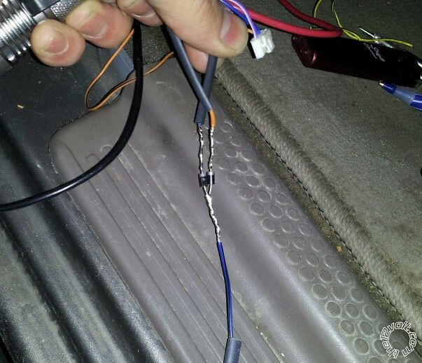
The following picture shows this exactly (on this exact model), the unlock & disarm outputs have diodes and lead to one wire that is connected to the vehicle's unlock wire:
Pin 2: NOT USED
Pin 3: (-) Lock Output - Yellow at SECU pin 11
Directed also lists the keysense wire as required. "Keysense RED / blue to WHITE/ red (required) (+) ignition key switch or SECU, gray 24 pin plug, pin 1"
I believe I did make this connection when I worked on this vehicle, though I have read from others that it's not needed.
You can leave it out if it starts fine without it. Otherwise, use a relay that's triggered by the "status output" to feed a constant (+) to the keysense during remote start.
Yellow Cake- Thank so much for all your help! I have also heard that the keysense is not needed in our vehicles. I will try it without at first and see if it starts. Did you use the XK05 bypass? I was thinking of going d2d with it, but have heard some bad things about this route. I think I would be better off going w2w, what do you think?
And I will take the domelight relay and use it for the trunk release H1/1 with a diode inline.
I used a Fortin key override all, I believe very similar to the XK05.
I would go w2w. There are only 3 additional connections needed for w2w, 12v, ground & ground while running (R/S status).
A few more questions...
Did you set up the relay for the Trunk release like this
*pin 85- H1/1 RED / white
*pin 86- Constant 12v(+)
*Pin 87- Ground wire(-)
*Pin 30- WHITE/ green(-) in kick panel harness to rear
And for the bypass(Xk05)
Brown-Ground wire Running to RS Status out(5701)
Blue- Ign power source- to pink wire(Xk05)
Violet- Data to PURPLE / Red around ign switch white 8 pin plug pin 1
Pink/white- ign wire(key side) BLACK/ white at Ign switch
Pink- Ing Wire (ECM side) BLACK/ white at ign switch
Red- Constant 12v(+)
Black- Chassis Ground
When I cut the Ign wire (BLACK/ white) do i connect H3/1 to key side or ECM side?
Trunk relay wiring looks good.
I think you may be confusing the "Transponder Plug Harness" for the "Ignition switch harness".
The thick gauge BLACK/ white ignition wire in the "ignition switch harness" does NOT get cut, it's where the H3/1 goes to only.
The XK05 diagram is not the easiest to understand. Your Pathfinder has the 8-pin transponder plug (FIG B).
Here's how the wiring for the XK05 should look:
- Brown to status output from RS is correct.
- Blue to the vehicle/ECM side of cut WHITE/ Black (pin-7) ignition wire in the transponder harness.
- Violet to the PURPLE / Red (pin-1) data wire in the transponder harness is correct.
- Pink/White to the key side of the cut ignition wire in the transponder harness.
- Pink to the vehicle side of the WHITE/ Black pin-7 (same place as the blue wire was connected).
- Red to the RS +12v supply.
- Black to the RS ground supply.
Ok that makes more sense.
Thanks again for all your help!