94 4runner astrostart guidance
Printed From: the12volt.com
Forum Name: Car Security and Convenience
Forum Discription: Car Alarms, Keyless Entries, Remote Starters, Immobilizer Bypasses, Sensors, Door Locks, Window Modules, Heated Mirrors, Heated Seats, etc.
URL: https://www.the12volt.com/installbay/forum_posts.asp?tid=135070
Printed Date: May 15, 2026 at 1:21 PM
Topic: 94 4runner astrostart guidance
Posted By: stolher
Subject: 94 4runner astrostart guidance
Date Posted: October 14, 2013 at 4:37 PM
I am trying to install an astrostart RS-624 in my wifes 94 4runner 3.0 auto.
I think I'm close but yet so far away.
I have ignition output attached to ignition #2
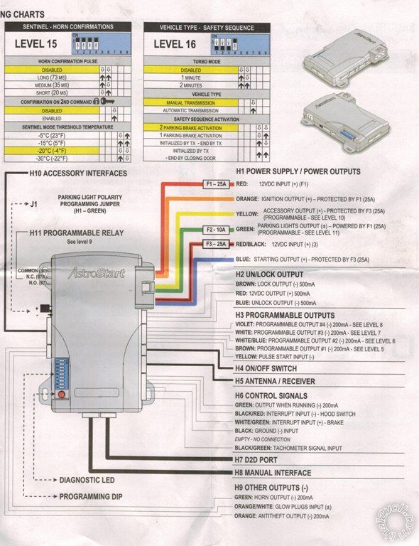
I have no clue what to do with accessory output, 12vdc output, anything in H3 programmable outputs (especially Pulse Start Input), Green ouput when running.
Once that is set the levels of programing have me scratching my head
Please help me! Im heading out of town in a couple days and I really want to get this taken care of
Thanks!
Replies:
Posted By: jpadj22
Date Posted: October 14, 2013 at 4:56 PM
The acc wire output goes to your acc wire on the 4 runner .
Ur GWR wire is typically used for ur anti grind relay.
-------------
No better feeling then getting a remote start to work right!
Posted By: stolher
Date Posted: October 14, 2013 at 5:11 PM
Wow how did I over look the accessory wire..
Any clarification on whether or not my ignition output goes to ignition one or two? Also pulse start input wire? Sounds important
Posted By: jpadj22
Date Posted: October 14, 2013 at 5:22 PM
You need to pick up both of the ignition wires. You can hook it up to ign. 1. Now look on the R/S for a wire that can be programed for 2nd ignition. Not sure if with this unit u have a + u can program for that. If not u typicaly have a -200ma for a 2nd ignition but you will need a relay to convert polarity. Theres a section on relays on this site. Take a look at it. Fyi make sure you test every wire you tap into. Make sure you pick up the right one.
-------------
No better feeling then getting a remote start to work right!
Posted By: stolher
Date Posted: October 14, 2013 at 5:40 PM
Any key words for the wire that goes to ignition wire #2?
Posted By: kreg357
Date Posted: October 14, 2013 at 5:42 PM
Here are a few resources...
The 12 Volt : https://www.the12volt.com/installbay/vehicles.html
Bulldog Security : https://www.bulldogsecurity.com/bdnew/vehiclewiringdiagrams.asp
Audiovox : https://techservices.audiovox.com/AccessRequest.aspx Requires free sign-up.
DEI : https://www.readyremote.com/main.asp
Download all the available guide lists, compile them into one list, then compare them to your vehicle. Use a Digital Multi Meter to locate and verify all
necessary wires. You can also make up a "cheat sheet" listing all your connections and post it on the forum for member review and input. There will be
many unused wires on the RS-624 system. Unfortunately I can't make out the diagrams you included and you will need an extra relay to power the
trucks IGN2 wire. Hopefully one of the H3 programmable outputs can do that.
-------------
Soldering is fun!
Posted By: auto enhancers
Date Posted: October 14, 2013 at 5:49 PM
94 4runner has 2-3 ign wires Blk\yellow, a second blk\yellow and blk\red
astro units have orange, white(p9) and I would use the green Plight wire as your third. It can be programed to ign. then take one of your programmable output (purple,brown,white,white\blue for plights and grab neg plights.
do not hook up the pulsed start wire, this is similar to dei's activation wire.
Posted By: stolher
Date Posted: October 14, 2013 at 5:57 PM
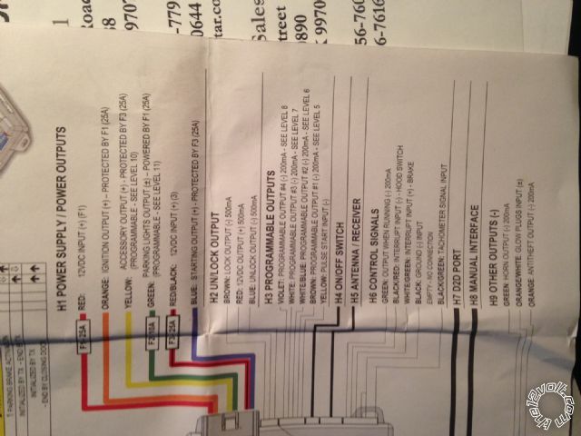
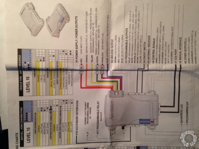
Posted By: stolher
Date Posted: October 14, 2013 at 5:59 PM
hope that picture is better. Im searching through the links posted. Thanks so much for the help thus far
Posted By: stolher
Date Posted: October 14, 2013 at 6:20 PM
I have all the diagrams complied from the links. They all say the same as what is listed on this site. Could anyone take the time and go down the list of wires and tell me what I can omit so I have a smaller list to work with.
Posted By: stolher
Date Posted: October 14, 2013 at 8:17 PM
Alright I now have the remote start turning the truck over but it will not start it. It flashes a code 4 the tach is hooked up. I've checked it 3 times now. The door lock still does nothing.
Posted By: stolher
Date Posted: October 14, 2013 at 8:51 PM
Alright if the key is set to the run position and I try to use the auto start it does nothing. However, if I use the auto start then while the engine is cranking over turn the key to the run position she fires right up and once I hit the brakes the module disables and flashes a code two like it should. Any thoughts?
Posted By: auto enhancers
Date Posted: October 15, 2013 at 8:49 AM
why don't you post what you have hooked up then we can tell you what you need.
Posted By: jpadj22
Date Posted: October 15, 2013 at 8:51 AM
Can you post all the conections you made? You do get a crank right? Are you sure you picked both of your ign wires?
-------------
No better feeling then getting a remote start to work right!
Posted By: stolher
Date Posted: October 15, 2013 at 12:07 PM
Absolutely
H1
Red and RED / black is on white-constant 12v
Orange is on ignition 1 BLACK / YELLOW
Yellow is on accessory blue/red
Green is on Parking lights green (+)
Blue is on black starter wire
H2
Brown is on blue/white in kick panel verified with test light that it's the lock
Red is nowhere
Blue is on blue / YELLOW in kick panel verified with test light that it's the lock
(Lock unlock doesn't work)
H3
Nothing is installed
H6
Green is not connected
BLACK/ red hood switch
WHITE/ green is on GREEN / WHITE off brake switch
Black is grounded
BLACK/ green is connected to the diagnostic connector for tach
H7 & H8
Nothing
H9
Green is connected to GREEN/ red under the column
ORANGE / white is not connected
Orange is not connected
Posted By: stolher
Date Posted: October 15, 2013 at 12:10 PM
jpadj22 wrote:
Can you post all the conections you made? You do get a crank right? Are you sure you picked both of your ign wires?
I do get crank. I only used ignition #1 not #2. Nothing on this sheet even indicates that it wants to be connected to ignition #2
Posted By: jpadj22
Date Posted: October 15, 2013 at 1:50 PM
You have to hook upboth ign wires from the 4 runner.
I cant seem to find the instalation guide online but guessing the ur harness H3 should have a wire that csn be programed as your 2nd ign.
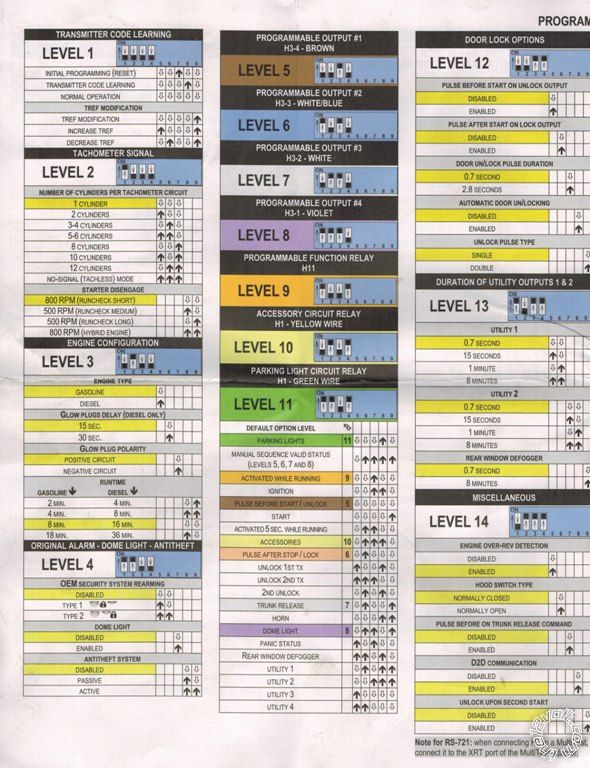
Can you post a pic of level 5,6,7and 8 programing?
-------------
No better feeling then getting a remote start to work right!
Posted By: stolher
Date Posted: October 15, 2013 at 2:04 PM
Posted By: stolher
Date Posted: October 15, 2013 at 2:06 PM
jpadj22 wrote:
You have to hook upboth ign wires from the 4 runner.
I cant seem to find the instalation guide online but guessing the ur harness H3 should have a wire that csn be programed as your 2nd ign.
Can you post a pic of level 5,6,7and 8 programing?
I have a picture of the instal guide on the first page of the thread towards the bottom.
Posted By: jpadj22
Date Posted: October 15, 2013 at 2:48 PM
I have never done an astrostart but this is what i understand from this programing instructions... you need to program the WHITE/ blue from harness h3 to ignition.
set the dip switches #1 on #2 off #3on #4 off...then #5 off #6 off #7 on #8 on # 9 off
you need to prees on the break so the unit can memorize your setting. the led should flash.
remember that you will get a (-) ignition output to the WHITE/ blue wire DO NOT CONNECT TO YOUR 2ND IGNITON. go to the section relays you need wire up one to convert polarity from a (-) to +. the wire coming from pin 87 will be your 2nd ign.  ------------- No better feeling then getting a remote start to work right!
Posted By: stolher
Date Posted: October 15, 2013 at 3:02 PM
Alright I'm out in town. I'll go pick up a 5 prong relay and give it a shot. Any idea on the door locks doing nothing?
Posted By: jpadj22
Date Posted: October 15, 2013 at 3:21 PM
When you say verified with test light how did u do it? You should be testing your wires with DMM . The wires from the 4 runner r a (-) you need to put your red test lead to 12v and black lead on youre suspect wire. When you press the lock or unlock you should see 12v. It goes away when you release it.
-------------
No better feeling then getting a remote start to work right!
Posted By: stolher
Date Posted: October 15, 2013 at 3:43 PM
So first I stripped the wires so I could test them then I grounded my multi meter and connected the pos to the wire. I hit the button and got a reading but it went so fast that I couldn't see what it was only that it was showing some voltage. So I took my test light and grounded it then connected the other end to the wire. Hit the button and every time I did the test light lit up
Posted By: stolher
Date Posted: October 15, 2013 at 3:51 PM
Also how do I determine what amp fuse to go with for my 12v on the relay?
Posted By: stolher
Date Posted: October 15, 2013 at 4:27 PM
I mirrored my fuse off the other protected circuits 25amps. Your the man! She fired right up. Now to dig into the locks
Posted By: stolher
Date Posted: October 15, 2013 at 4:58 PM
Door locks now work. I tapped into the wires after the relay. My last question is the horn. It does nothing. I'd like to activate the panic feature in it
You guys are awesome!
Posted By: auto enhancers
Date Posted: October 15, 2013 at 5:18 PM
stolher wrote:
Absolutely
H1
Red and RED / black is on white-constant 12v
Orange is on ignition 1 BLACK / YELLOW
Yellow is on accessory blue/red
Green is on Parking lights green (+)
Blue is on black starter wire
H2
Brown is on blue/white in kick panel verified with test light that it's the lock
Red is nowhere
Blue is on blue / YELLOW in kick panel verified with test light that it's the lock
(Lock unlock doesn't work)
H3
Nothing is installed
H6
Green is not connected
BLACK/ red hood switch
WHITE/ green is on GREEN / WHITE off brake switch
Black is grounded
BLACK/ green is connected to the diagnostic connector for tach
H7 & H8
Nothing
H9
Green is connected to GREEN/ red under the column
ORANGE / white is not connected
Orange is not connected
second ign is the white harness that comes in the box. It it is connected to the pins at the top of the brain, pins 30 and 87. This is a built in relay for the rs system.
you will need to cut the harness and connect 1 side to 12 volts and the other to the second ign.
as for locks you will need to test to be sure they are the correct wires and then you can trigger them with the appropriate trigger(neg,pos)
Posted By: stolher
Date Posted: October 15, 2013 at 6:33 PM
Everything is hooked up and works as advertised. Thanks to all who helped. I couldn't have done it without you!
Posted By: jpadj22
Date Posted: October 16, 2013 at 8:13 AM
Awsome great job.
-------------
No better feeling then getting a remote start to work right!
|