2007 dodge grand caravan
Printed From: the12volt.com
Forum Name: Car Security and Convenience
Forum Discription: Car Alarms, Keyless Entries, Remote Starters, Immobilizer Bypasses, Sensors, Door Locks, Window Modules, Heated Mirrors, Heated Seats, etc.
URL: https://www.the12volt.com/installbay/forum_posts.asp?tid=135160
Printed Date: May 13, 2026 at 6:25 PM
Topic: 2007 dodge grand caravan
Posted By: opiateofsorrow
Subject: 2007 dodge grand caravan
Date Posted: October 27, 2013 at 9:26 PM
Hello all. First I am very new to this forum, but have been grazing over the site for quite some time now. I am presently installing a car alarm/starter combo in my 2007 Dodge Grand Caravan... I have yet to purchase a bypass module for the van, but there are several shops around town offering them.
Anyway, a few questions... And please forgive what might seem like fragmented or questions that don't make sense. I've scanned the 12volt site but still can't quite make sense of a few things.
1.Which bypass module should I use? And is there a general idea on how to wire up the 2nd starter wire to this module? From what I've been reading you need a negative trigger through a 180 ohm resistor... And I'm supposed to run this through a relay but on the other end of the coil for the SPDT switch, people keep mentioning "Run to ground of BCM when on." Where exactly do I run the second starter wire to in my car alarm?
Here is the installation instructions for my car alarm...
40.Attention for installation
①6 PIN Remote start-up power socket
PIN1: Black and yellow wire Starter switch-on wire (+12V).
It is connected to ignition lock wire where +12V appears in the Starter key position. This signal means engine start-up.
PIN2: Blue wire IGN 1 wire, output signal +12V.
It is connected to ignition lock wire where +12V appears in the Ignition ON key position and does not disappear in the Starter position.
PIN3: Orange wire An output signal +12V ACC auxiliary equipment.
It is connected to ignition lock wire where +12V appears in the ACC and Ignition ON key position.
PIN4: Thick red wire Remote start-up circuit power supply wire (+12V)
It is connected to ignition battery + terminal via 30A fuse.
PIN5: Thin red wire System power supply wire (+12V)
It is connected to ignition battery + terminal via 3A fuse.
PIN6: Blue and red wire IGN 2 wire, output signal +12V.
It is connected to ignition lock wire where +12V appears in the Ignition ON key position and disappears in the Starter position.
②6 PIN central lock connection socket
System has in-built power relays for central lock control. Wiring for connection of central lock is made in a separate six-pin socket. Please refer to central lock Installation diagram.
PIN1: White wire Central contact for central lock closing relay
PIN2: Yellow wire Normally open contact for central lock closing relay
PIN3: Orange wire Normally closed contact for central lock closing relay
PIN4: Orange and black wire Normally closed contact for central lock opening relay
PIN5: Yellow and black wire Normally open contact for central lock opening relay
PIN6: White and black wire Central contact for central lock opening relay
③8 PIN main socket 1
PIN1: No connection
PIN2: Black wire System , connect to ground (Ensure reliable contact)
PIN3: Yellow and red wire Immobilizer bypass output (250mA), main unit output 250mA pulse while engine running.
PIN4: Green wire Siren output (3A).
PIN5: Purple wire Channel 2 output, wire for trunk release(250mA, 0.8 sec, default setting) or windows closer(250mA, 25 sec) or potential pulse(250mA, 30 sec).
This function can be program setting.
PIN6: Thick brown wire Parking light output wire (7.5A)
PIN7: Yellow wire Engine-stopper control wire (250mA output after arming system or 250mA output after disarming system with program setting), connected to engine-stopper relay. Please refer to installation diagram 1.
PIN8: Thick brown wire Parking light output wire(7.5A)
④8 PIN main socket 2
PIN1: BROWN / white wire Negative hand-brake trigger input
PIN2: BROWN / black wire Positive foot-brake trigger input
PIN3: Gray wire Negative trunk trigger input
PIN4: White wire Negative door trigger input
PIN5: WHITE/ Red wire Positive door trigger input
PIN6: Blue/black wire Control input to start engine from outside device, the negative pulse time is not less than 100ms.
And what about the pin 7 and 8 below? Where do I hook these up to exactly?
PIN7: Blue/red wire Engine start testing wire 1, input for engine high-voltage, signal to be effective more than 1V .
Please refer to installation diagram 2.
PIN8:Blue/ white wire Engine start testing wire 2 input for oil pressure sensor, signal to be effective more than 6V .
Please refer to installation diagram 2.
Note: Depending on your need to install testing wire 1 or testing wire 2.
⑤Selection manual or automatic gearshift car
Selection of manual or automatic gearshift car is done using wire loop (refer to installation diagram 2):
Keep wire loop: Manual gearshift car
Cut wire loop: Automatic gearshift car
ATTENTION:
For manual gearshift car, please do not cut the wire loop outside the main unit.
I have both the plain grey Chrysler key and the black one with the lock/unlock symbol.
Thanks in advance for your help guys.
Replies:
Posted By: smokeman1
Date Posted: October 28, 2013 at 6:51 AM
Here is a link to a Town & Country I did a while back. Included is info from Kreg357 install on Caravan. It was a rather easy install. I believe the is a air bag under the lower dash cover. Just be aware.
What brand/model of remote start/alarm are you installing?
https://www.bulldogsecurity.com/bdnew/vehiclewiringdiagrams.aspx
https://diagrams.marktoonen.nl/DOWNLOADS/29358_CARAVAN_CHRYSLER%20MINI%20VAN%20STARTER%202%20DIAGRAM.pdf
-------------
When all else fails, Read the Instructions
Support the12volt.com Make a Donation
Posted By: kreg357
Date Posted: October 28, 2013 at 7:27 AM
Posted By: opiateofsorrow
Date Posted: November 03, 2013 at 12:53 AM
Thanks guys...
It is a generic car alarm that I ordered from a supplier in China.
I've tried tirelessly to get the direct fax 1076 document for the door switches
... Alas every post that directs me to the directed site doesn't work... because you need the password and I just don't have access to that.
I am using a Fortin Evo-all bypass module but I am having issues with programming it. I get all the way to the last step when the light goes orange, when I shut the ignition off the blue light flashes and orange and red are solid.
Posted By: kreg357
Date Posted: November 03, 2013 at 1:43 AM
There is a copy of Direct Fax / Tech Tip 1076 in the downloads section of this site. Here is a link :
https://www.the12volt.com/installbay/file.asp?ID=514 However, if you are using the EVO-ALL bypass
module, it will supply a Door Trigger Input signal for your R/S unit. You will have to go W2W with
the EVO-ALL to R/S, so all necessary Gray dashed lines in the EVO-ALL Type 2 diagram must be made.
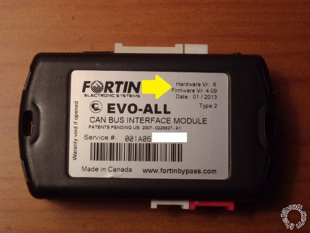
EVO-ALL programming : What version Firmware is loaded onto the EVO-ALL? For your application,
it can not be any higher than Ver 4.06. Newer versions do not support the J1850 Data system in your
mini-van. Most newer EVO-ALL's are at Ver 4.09 or Ver 4.18. Here is a photo of where to find this info.
Hopefully you have the Fortin FlashLink USB cable needed to re-flash the EVO-ALL or a local shop that
can do this for you, if necessary.
After looking at the R/S's wire listing you posted above, I'd be real interested in seeing a wire by wire
connection list between it, the EVO-ALL and the mini-van ( especially the MUX relay wiring ). ------------- Soldering is fun!
Posted By: opiateofsorrow
Date Posted: November 03, 2013 at 9:07 AM
thank you very much.
for the evo-all it does say 4.06. The shop I bought it from gave me directions printed on how to install it... but pretty much didn't mention to me that if I didn't have the flashlink cable, that I had to snip the red and black cable and connect red to 12v constant and black to ground. I ended up going to the Fortin website.
I've found a lot of resistance from shops
by the way I got all my resistors from a site called Digikey. they were awesome. ordered Friday and I received all required by Monday.
my search began for all the required resistors, spdt relays and bypass module etc. They all seem shocked I'm doing it myself, they sound very judgemental when I ask questions. The gentleman from Fortin was very despondent with me. I'm sure its half because they think I'm chop sueying my van (which I an beginning to believe myself) and half because the shops want me to pay for their business anyway ..
...
Cut wire for automatic/standard operation
I diode isolated all the door pinouts... but I didn't diode isolate the bcm because of the lack of direct fax 1076. the alarm was going nuts when I started it up, I'm wondering if this was why. the unlock button wouldn't disengage it. could hear relays clicking on and off like mad plus the lights on the dash were flicking on and off.
I don't believe I diode isolated the trunk pin yet either.
for the brake lights, I used a relay first to convert to a negative trigger and then used a resistor and relay as described in the write ups to isolate.
I followed the diagrams for lock unlock, using two relays and separate resistors going to the one wire for lock unlock. following all numbers on spdt relays.
I haven't wired the evo all like the document 2 stated. got a little confused with the grey dotted lines. the wire up method the guy gave me at the car alarm shop only said to wire purple / YELLOW parallel to the data, and cut pink/white wire for ignition, placing yellow and WHITE/ red ontransponder side in series, WHITE/ green on other side in series.
if you have a link to that evo all sheet for gray dotted wires it would be much appreciated.
sorry, my van is at my parents place. I was working outside and got snowed on, so I borrowed his van and have to go back to drive it to my friends shop.
Posted By: opiateofsorrow
Date Posted: November 03, 2013 at 9:12 AM
I'm becoming confused as well about the accessory, IGN1 IGN2 Starter 1, 2 etc. the car alarm seems contrary to the write ups where they state it only has IGN1.
Posted By: opiateofsorrow
Date Posted: November 03, 2013 at 12:32 PM
Okay... So upon double checking the Fortin bypass again... It is actually 4.18 Firmware version. :( I guess I am stuck now. Do shops usually have older firmware versions in stock or they all get the newest one usually? I have to go back and talk to them about switching or getting a refund...
I have decided to opt out of the Chinese-english alarm and buy something more compatible and recommended by you guys. As far as I'm aware my van doesn't have the trunk release option, although its quite possible this can be fixed so the trunk unlocks with a push of the alarm fob button.
Can you guys tell me what alarms are compatible with the Fortin Evo-Alls? I'm looking with something that has 3000-5000 ish range, lock unlock start, turn signal flash etc. Please let me know.
Posted By: kreg357
Date Posted: November 03, 2013 at 12:44 PM
The Fortin FlashLink USB cable is only necessary to load the firmware on the EVO-ALL bypass module. Once the V4.06 firmware is loaded, you no
longer need that cable.
The EVO-ALL's 4 Pin connector you mentioned cutting is used to communicate with the R/S unit. If you had purchased a R/S unit that is capable
of D2D comm with the EVO-ALL, that cable would be used, un-cut. Being as you have an off-brand R/S system, you must connect them via the
W2W method. That is where you cut that 4 Pin harness and manually connect the power, ground and GWR signals along with all the rest of
the necessary wires ( shown in dashed Gray ). As you can see, it gets complicated very quickly. Most +12V shops don't really have the time
to step you through the entire process. If you look at it from their point of view, they are loosing money on your job and spending a lot of
precious time helping you figure out how to successfully complete your install, knowledge they spent years acquiring.
Anyway, please take a close and carefully look at the EVO-ALL install guide. In the beginning ( Page 4 ), it has a chart that details exactly what the
bypass module will do when installed in your mini-van. Specifically, it will handle the locks for you through the J1850 Data connection. There is
no need for you to connect the R/S to the mini-van's lock wire with relays and resistors. Just follow the Type 2 diagram and it's Dashed Gray
lines. Again, the EVO-ALL will collect door trigger status info from the mini-van off the J1850 Data wire and output a signal called "Door Status"
for use by your R/S unit ( another dashed Gray wire connection ). There is no need for diodes and R/S to mini-van wire connections for the
door triggers. The EVO-ALL even supplies a Tach signal for your R/S unit. The EVO-ALL isn't cheap, so you might as well take advantage of
all it's resources.
Remember that your off-brand R/S unit is generic. It was designed to work with a wide variety of vehicles. It will have some wires not used
for your specific application. Additionally, it has some limitations that will make your install slightly difficult. The one I'm most concerned with
is it's lack of a Starter2 output which is specifically needed for your mini-van install as shown in the EVO-ALL Type 2 diagram.
Oh boy, a lot of typing for nothing after your last post. The shop that sold you the EVO-ALL should have asked you the vehicle application and
flashed it with their cable prior to sale. They might do that for you. As far as good quality systems from major manufacturers, look at Viper,
Compustar, Audiovox, etc. Just remember that all major brands do not support DIY installs.
-------------
Soldering is fun!
Posted By: opiateofsorrow
Date Posted: November 03, 2013 at 1:08 PM
Sorry for wasting your fingertips. I am learning a lot with your help so again thank you. I will take what you have given me and reanalyze everything. what you typed was not in vain by any means, being but a fawn I am making mistakes as I go and I think trying to save dollars with a cheaper Chinese brand with hopes if will work just as well. in this case tried tested and true is prevailing.
talked to a small business owner just a few minutes ago, he mentioned to me he's had a lot of problems with the smartcar alarms I purchased. he didn't want to help install it because he didn't want to deal with me coming back constantly complaining about its improper functioning.
live and learn
Posted By: smokeman1
Date Posted: November 03, 2013 at 1:15 PM
I would recommend a Viper 5301 or 4204, Same unit. Its just a remote starter that has very good range. It is what I installed in the Town & Country mentioned earlier.
A bit more range is the Viper 5501 or 4704. Both remote starters only.
All of the above will have the ability to do the Starter 2.
Alarm can be a bit of a pain if not done right. False alarm or windy days setting off the alarm, so I tend to stay away from them.
Kreg will have good recommendations also. 
I am familiar with the Viper, Python, Clifford line. ------------- When all else fails, Read the Instructions
Support the12volt.com Make a Donation
Posted By: opiateofsorrow
Date Posted: November 04, 2013 at 10:36 AM
Question... I called the gent whom I purchased the bypass from. He's saying he can update it to any firmware necessary. is this true or does he not know what he's talking about? I would think firmware is something you can't modify unless you get the board specific to that version.
Posted By: smokeman1
Date Posted: November 04, 2013 at 11:34 AM
The Fortin can be re-flashed.
-------------
When all else fails, Read the Instructions
Support the12volt.com Make a Donation
Posted By: opiateofsorrow
Date Posted: November 09, 2013 at 5:21 PM
hey guys... okay so I was vigilant and decided to try this again. got everything working but the start. I don't have a starter 2 output from my alarm, it needs to be a negative output. is there any way to use the first starter and isolate with relays and the 180 ohm resistor? searched the forums too. .
Posted By: opiateofsorrow
Date Posted: November 09, 2013 at 5:22 PM
wired the Fortin up properly, it programmed fine. starter goes to start and cuts out after half a second. can the tach wire be hooked up to the high voltage wire for engine startup test?
Posted By: kreg357
Date Posted: November 09, 2013 at 5:49 PM
Try connecting the EVO-ALL Tach output Pink wire to this wire on your R/S system :
PIN7: Blue/red wire Engine start testing wire 1, input for engine high-voltage, signal to be effective more than 1V .
Please refer to installation diagram 2. There might be some kind of Tach Learn process required, also.
-------------
Soldering is fun!
Posted By: opiateofsorrow
Date Posted: November 09, 2013 at 6:19 PM
that wire is intended to be coiled 5 times around a high voltage wire. I looped it around the spark plug wire
Posted By: kreg357
Date Posted: November 09, 2013 at 6:22 PM
Here is a diagram of how to wire the Dodge Grand Caravans Starter and MUX wires from the one Smartcar Starter output :
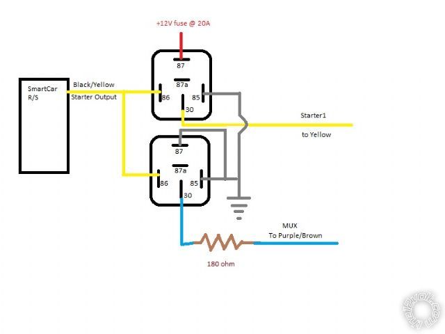
------------- Soldering is fun!
Posted By: kreg357
Date Posted: November 09, 2013 at 6:24 PM
Re Tach / Hi Voltage wire. OK, not real common but if it works... ( Don't have the install guide to actually read up on your system.) ------------- Soldering is fun!
Posted By: opiateofsorrow
Date Posted: November 09, 2013 at 6:25 PM
you are an install god I don't care what anyone says
Posted By: opiateofsorrow
Date Posted: November 25, 2013 at 10:26 AM
Hey guys! So after much trial tribulation and countless hours of wizing my fiancee off, I finally got the alarm starter combo working in my van.
The issue ended up being the cheap Chinese R/S alarm. It was fried, so I ended up buying a Nustart NUAS-4502. Took me about 6 hours of removing the old alarm, installing tach learn etc and it works like a charm.
I will be posting how I installed the alarm in detail with the Fortin Bypass, to save everyone the hell I experienced. It definitely didn't help that I was a novice.
Special thanks to Smokeman and Kreg for all the massive help. I used the Starter relays to convert into MUX/Starter feeds like that diagram.
Man that RS232 data port for Fortin bypasses saves a ton of issues !! buy newer alarms for newer vehicles..
|