I am trying to figure out the wiring for the remote door locks and have located the door pins and lock unlock wires all negitive based on my wiring diagrams.
the remote starter is a prostart ct3371
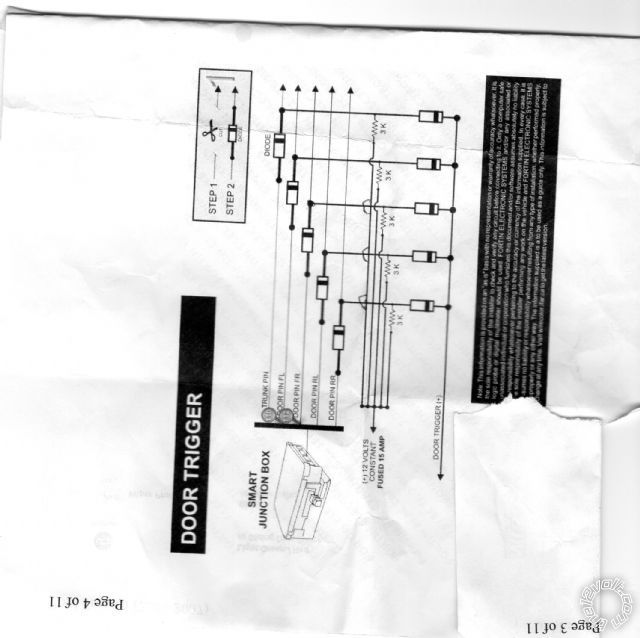
in the diagram above it shows to cut and install a diod then then conect power with 3k resister then a second diod and door triger positive.
Is door triger positive, the remote positive door input?
I have a(-) negitive door input
(+) positive door input
(-) unlock output
( -) lock out put
Is this the best way to connect this or am I not understanding the diagram?
I would think you would just use the negitive inputs to pulse the negitive pins
any help is appreciated thanks
If this is only a remote starter then you dont have to worry about the door triggers
-------------
Jeff
Velocity Custom Home Theater
Mobile Audio/Video Specialist
Morden, Manitoba CANADA
I would like to use the door locks if possible to get rid of one remote.
Door Locks and Door Trigger are 2 completely different things.
If you still want to do door locks, and there is a door lock output on your RS unit.
Power Unlock DARK BLUE/GREEN (-) IN HARNESS IN DRIVERS KICKPANEL
PowerLock WHITE/ VIOLET (-) IN HARNESS IN DRIVERS KICKPANEL
Notes read also at smart junction box under drivers side dash. Pins 1 and 3.
i am an idiot wrote:
Door Locks and Door Trigger are 2 completely different things.
Thanks maybe a little info would be helpfull Im a little stupid but I do know how to fix things and usually figure things out. Some day you might need some info about somthing some one else is more informed about thanks for your time.
i am an idiot wrote:
If you still want to do door locks, and there is a door lock output on your RS unit.
Power Unlock DARK BLUE/GREEN (-) IN HARNESS IN DRIVERS KICKPANEL
PowerLock WHITE/ VIOLET (-) IN HARNESS IN DRIVERS KICKPANEL
Notes read also at smart junction box under drivers side dash. Pins 1 and 3.
thanks for the response
I have the wires located but am not sure whether I need the above wiring or can just conect the negitive pulse to the lock and lock wires
thanks
The diagram you posted is for door trigger. That is what sets the alarm off if the door gets opened. Just connect the door lock wires from your system to the 2 wires I posted.
Thanks
Thats what I thought but couldent figure out why the wiring diagram was included with no explanation.