4206p 00 malibu guide?
Printed From: the12volt.comForum Name: Car Security and Convenience
Forum Discription: Car Alarms, Keyless Entries, Remote Starters, Immobilizer Bypasses, Sensors, Door Locks, Window Modules, Heated Mirrors, Heated Seats, etc.
URL: https://www.the12volt.com/installbay/forum_posts.asp?tid=135294
Printed Date: April 06, 2026 at 9:29 PM
Topic: 4206p 00 malibu guide?
Posted By: weaz4200
Subject: 4206p 00 malibu guide?
Date Posted: November 15, 2013 at 8:15 PM
All I'm looking to do is...
1) Obviously Remote start to work
2) Door locks and trunk release to work
That's it for now. Obviously the system has many capabilities but I just need the list above to work. Can someone please help me weed out which connection I don't need?
I'll probably have a few questions a bit later but right now I'd like to look at the Install Guide and eliminate wires I won't be using
Here's the guide breakdown
Main Harness (H1), 6-pin connector
H1/1 RED (+)12VDC CONSTANT INPUT
H1/2 BLACK (-) CHASSIS GROUND
H1/3 BROWN (-) 200mA HORN HONK OUTPUT
H1/4 WHITE/ BROWN LIGHT FLASH ISOLATION WIRE - PIN 87a light flash relay
H1/5 WHITE PIN 30 of LIGHT FLASH RELAY
H1/6 ORANGE 500 mA GROUND WHEN ARMED OUTPUT
Auxiliary/Shutdown Harness (H2), 24-pin connector
H2/1 PNK/WHITE (-) 200mA FLEX RELAY CONTROL OUTPUT
H2/2 BLACK/ WHITE (-) NEUTRAL SAFETY INPUT
H2/3 BLUE/WHITE (-) 200mA 2ND STATUS /REAR DEFOGGER OUTPUT
H2/4 GREEN/ BLACK (-) 200mA FACTORY ALARM DISARM OUTPUT
H2/5 RED / WHITE (-) 200mA TRUNK RELEASE OUTPUT
H2/6 GREEN (-) DOOR INPUT**
H2/7 BLACK / YELLOW (-) 200mA DOME LIGHT OUTPUT
H2/8 EMPTY ------------------------------------
H2/9 DARK BLUE (-) 200mA STATUS OUTPUT
H2/10 PINK (-) 200mA IGNITION 1 OUTPUT
H2/11 WHITE/ BLACK (-) 200mA AUX 3 OUTPUT
H2/12 VIOLET (+) DOOR INPUT
H2/13 WHITE/ VIOLET (-) 200mA AUX 1 OUTPUT
H2/14 VIOLET/BLACK (-) 200mA AUX 2 OUTPUT
H2/15 ORANGE / BLACK (-) 200mA AUX 4 OUTPUT
H2/16 BROWN (+) BRAKE SHUTDOWN INPUT
H2/17 GRAY (-) HOOD PIN INPUT (NC OR NO)
H2/18 VIOLET / YELLOW (-) 200mA STARTER OUTPUT
H2/19 BLUE** FACTORY HORN INPUT (Use Jumper to set polarity)
H2/20 GRAY/BLACK (-) DIESEL WAIT TO START INPUT
H2/21 WHITE/ BLUE ACTIVATION INPUT
H2/22 ORANGE (-) 200mA ACCESSORY OUTPUT
H2/23 VIOLET/WHITE TACHOMETER INPUT
H2/24 GREEN / WHITE (-) 200mA FACTORY ALARM ARM OUTPUT
Remote Start harness (H3), 8-pin connector
H3/1 PINK (+) IGNITION 1 INPUT/OUTPUT
H3/2 RED / WHITE +12V FUSED (30A) IGNITION 2/FLEX RELAY INPUT
H3/3 ORANGE (+) ACCESSORY OUTPUT
H3/4 VIOLET (+) STARTER OUTPUT
H3/5 RED +12V FUSED (30A) IGNITION 1 INPUT
H3/6 PINK/WHITE IGNITION 2/FLEX RELAY OUTPUT
H3/7 PINK/BLACK FLEX RELAY INPUT 87a (IF REQUIRED) OF FLEX RELAY
H3/8 RED / BLACK +12V FUSED (30A) ACCESSORY/STARTER INPUT
Door Lock, 3-pin connector
1 BLUE (-) 500mA UNLOCK OUTPUT
2 EMPTY NOT USED
3 GREEN (-) 500mA LOCK OUTPUT
Any help would be appreciated.
Thanks,
ROB
Replies:
Posted By: kreg357
Date Posted: November 15, 2013 at 8:54 PM
Hi Rob,
Welcome to the 12V Forum!
Main Harness (H1), 6-pin connector
H1/1 RED (+)12VDC CONSTANT INPUT Red @ ignition switch harness
H1/2 BLACK (-) CHASSIS GROUND Chassis Ground
H1/3 BROWN (-) 200mA HORN HONK OUTPUT Black @ ignition switch harness
H1/4 WHITE/ BROWN LIGHT FLASH ISOLATION not used
H1/5 WHITE PIN 30 of LIGHT FLASH RELAY ***Set for (+) Brown @ Headlight Switch
H1/6 ORANGE 500 mA GROUND WHEN ARMED OUTPUT not used
Auxiliary/Shutdown Harness (H2), 24-pin connector
H2/1 PNK/WHITE (-) 200mA FLEX RELAY CONTROL OUTPUT not used
H2/2 BLACK/ WHITE (-) NEUTRAL SAFETY INPUT Chassis ground ( if auto trans )
H2/3 BLUE/WHITE (-) 200mA 2ND STATUS /REAR DEFOG OUTPUT not used
H2/4 GREEN/ BLACK (-) 200mA FACTORY ALARM DISARM OUTPUT not used
H2/5 RED / WHITE (-) 200mA TRUNK RELEASE OUTPUT To Pin 85 of relay **
H2/6 GREEN (-) DOOR INPUT** not used
H2/7 BLACK / YELLOW (-) 200mA DOME LIGHT OUTPUT not used
H2/8 EMPTY ------------------------------------
H2/9 DARK BLUE (-) 200mA STATUS OUTPUT bypass module GWR
H2/10 PINK (-) 200mA IGNITION 1 OUTPUT not used
H2/11 WHITE/ BLACK (-) 200mA AUX 3 OUTPUT not used
H2/12 VIOLET (+) DOOR INPUT not used
H2/13 WHITE/ VIOLET (-) 200mA AUX 1 OUTPUT not used
H2/14 VIOLET/BLACK (-) 200mA AUX 2 OUTPUT not used
H2/15 ORANGE / BLACK (-) 200mA AUX 4 OUTPUT not used
H2/16 BROWN (+) BRAKE SHUTDOWN INPUT Light Blue @ Brake Pedal Switch
H2/17 GRAY (-) HOOD PIN INPUT (NC OR NO) to supplied hood pin
H2/18 VIOLET / YELLOW (-) 200mA STARTER OUTPUT not used
H2/19 BLUE** FACTORY HORN INPUT not used
H2/20 GRAY/BLACK (-) DIESEL WAIT TO START INPUT not used
H2/21 WHITE/ BLUE ACTIVATION INPUT not used
H2/22 ORANGE (-) 200mA ACCESSORY OUTPUT not used
H2/23 VIOLET/WHITE TACHOMETER INPUT see note 1
H2/24 GREEN / WHITE (-) 200mA FACTORY ALARM ARM OUTPUT not used
** The Trunk Release Output is (-) and the Malibu needs a (+) signal. Use a 30/40 Amp SPDT relay w/ 10 Amp fuse
as shown below :
Relay Pin 85 to H2/5
Relay Pin 86 & 87 to +12V constant through 10 Amp fuse
Relay Pin 30 to Malibu BLACK/ WHITE (+) @ TRUNK RELEASE SWITCH
Relay Pin 87a not used
Note 1 : The TACH wire on the 4-Cylinder is a WHITE (AC) at the IGNITION COIL, on the V6, the TACH wire is a
PURPLE / WHITE at the coil pack.
Remote Start harness (H3), 8-pin connector
H3/1 PINK (+) IGNITION 1 INPUT/OUTPUT Pink @ ignition switch harness
H3/2 RED / WHITE +12V FUSED (30A) Red @ ignition switch harness
H3/3 ORANGE (+) ACCESSORY OUTPUT Orange @ ignition switch harness
H3/4 VIOLET (+) STARTER OUTPUT Yellow @ ignition switch harness
H3/5 RED +12V FUSED (30A) IGNITION 1 INPUT Red @ ignition switch harness
H3/6 PINK/WHITE FLEX RELAY OUTPUT ***set for IGN2 Green @ ignition switch harness
H3/7 PINK/BLACK FLEX RELAY INPUT 87a not used
H3/8 RED / BLACK +12V FUSED (30A) ACC/STARTER INPUT Red @ ignition switch harness
Door Lock, 3-pin connector
1 BLUE (-) 500mA UNLOCK OUTPUT To 451M door lock module
2 EMPTY NOT USED
3 GREEN (-) 500mA LOCK OUTPUT To 451M door lock module
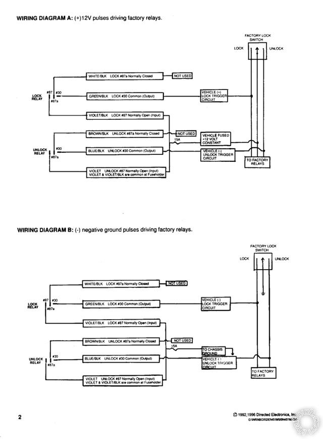
The Directed 451M door lock module is inexpensive ( > $9 ), neat and easy to use. You can also use 2 SPDT realys
as shown in this Type A (+) diagram : https://www.the12volt.com/doorlocks/page3.asp#3wp
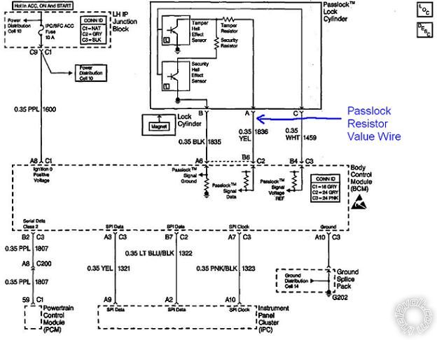
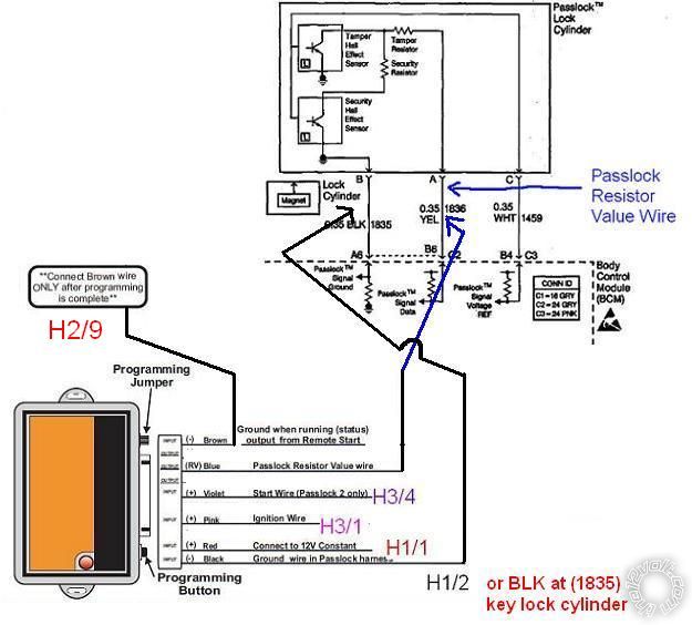
You will need a bypass module for the Passlock2 immobilizer system. Popular DIYer modules include :
Directed 555L, 556L, 556LW, PLXR, PLJX; Fortin PASSLOCK-SL2 v.2; ADS iDatalink ADS TBSL PL
You can also bypass the Passlock2 with a resistor and some relays. Here is the process :
https://documents.audiovox.com/700054.pdf
-------------
Soldering is fun!
Posted By: weaz4200
Date Posted: November 15, 2013 at 9:22 PM
Doorlock 3 pin.
1 BLUE (-) 500mA UNLOCK OUTPUT
2 EMPTY NOT USED
3 GREEN (-) 500mA LOCK OUTPUT
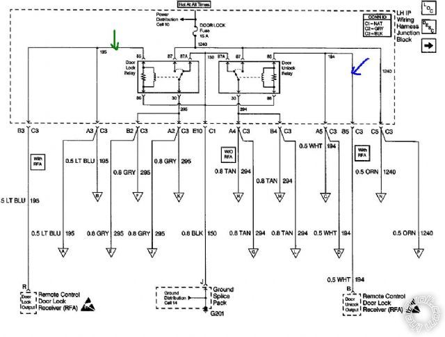
Couldn't I wire it up as per this diagram... Note color of arrows corresponding to wire colors from above and tap into those wires?
Posted By: kreg357
Date Posted: November 15, 2013 at 10:01 PM
That is basically where you are going to connect to. Notice the wire colors are the same as the wire guide
listing and connecting in the DKP is pretty easy. However, you need to supply that point with a (+) input signal,
not the low current (-) output that the 4206 supplies. That is the reason for the relays or 451M module, to convert
the 4206's (-) output to the (+) output the car needs.
The relays coils are tied together at Pin 86, which goes to E10 C1 Black wire to chassis ground, G201. Pin 85
needs to be +12V to energize the coil.
Here is a link to the Bulldog Security wire list with photos for your car :
https://diagrams.marktoonen.nl/printlist.aspx?MakeID=13&ModelID=20284
-------------
Soldering is fun!
Posted By: weaz4200
Date Posted: November 15, 2013 at 10:30 PM
That is the reason for the relays or 451M module, to convert the 4206's (-) output to the (+) output the car needs. The relays coils are tied together at Pin 86, which goes to E10 C1 Black wire to chassis ground, G201. Pin 85 needs to be +12V to energize the coil.
I guess that makes sense.
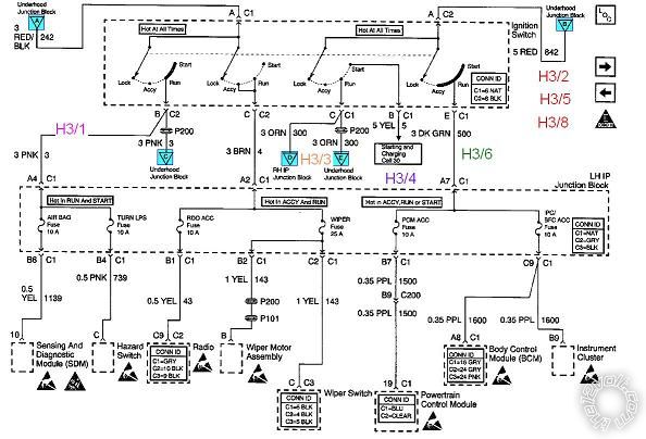
So now the H3 connector... Note image of proper wiring placement (i made pic smaller as the forum rules state 640 pixels. If need be I'll make bigger)
Questions
1)Why H3/3 Orange to orange and not the BRN in the wiring diagram?
2)H3/6 Pink/White to DRK GRN? What is the purpose of FLEX RELAY OUTPUT ***set for IGN2? What does this mean?
Posted By: weaz4200
Date Posted: November 16, 2013 at 12:10 AM
Now for H1 harness.
H1/1 I'll just tap into the same place as the (H3/2,H3/5,H3/8) as above.
H1/2 obvious chassis ground
H1/3 Diagram in previous post doesn't show a black wire for whatever reason... So note pic. I should be okay with tapping in there correct?
Also, having a problem with H1/5 BROWN?
Headlamp switch schematic....
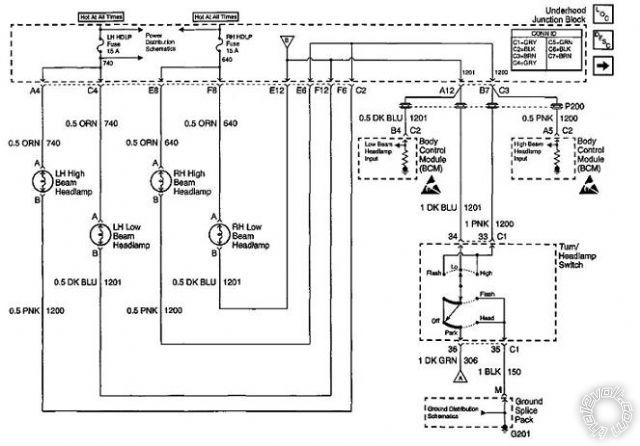
Doesn't show a brown wire in that particular diagram.
But, Front Park/turn and marker lamps diagram... That what I'm looking for? Also stated "***Set for (+)" AS IN? The fuse jumper in the remote start module?
Posted By: kreg357
Date Posted: November 16, 2013 at 7:37 AM
Ok. This might be a very long reply.
First we should start off with a few basic "rules" for auto electronics as applied to the installation of after-market
accessories, like your remote start with keyless entry.
1. It is best to keep the wires short. Besides being neater, this will eliminate parasitic line loss issues that occur
in high current runs and would necessitate larger gauge wire. In-line fuses should be within one foot of their
connection / source.
2. Wherever possible, try to keep the wire connections inside the passenger cabin. This will protect the connections
from the weather, the heat of the engine compartment and the possible rubbing & chaffing if not positioned and
run perfectly.
3. As you have seen looking at the vehicles wiring diagrams, there are multiple places and wires where you can
make your connection to achieve the desired result. As the installer, you can / will decide the exact location.
Typically, installers will look for a place that provides good access for the required soldering tools, while
following Rules 1 and 2 above.
4. The majority of installers will not disconnect the battery during an install. This is to prevent radio preferences
from being lost, reseting computers ( "Not Ready" for state emission inspections ) and other reasons. It
also allows testing / re-testing during the wire connection process. Aside from the main ignition harness
connector, if any connector has to be unplugged, the battery should be disconnected.
5. During the install, running the wires from the control unit to their connection point neatly and then cutting them
to length is an important part of the job. Making a good solder connection and insulating that joint with a quality
electric tape ( Scotch Super 33+ ) is even more important.
6. While planning and preparation is very important, the goal is to install the after-market accessory in a way that
will provide many years of trouble-free use, as efficiently as possible. Most of the engineering of the accessory
is done and appropriate for the vehicles needs. The wires are the correct gauge and long enough for most vehicle
applications. The axiom of K.I.S.S. can come into play. Over thinking an issue can impede the install. The wire
guide listings available from Bulldog Security and Auviovox generally supply the "tried and true" wires and locations.
7. One of the most important tools used during the install is the Digital Multi Meter. Even though you have the full
vehicle wiring documentation, you should test and verify each wire before making a connection. Often times a
connection will be easiest by catching the desired wire in a kick panel or door sill but locating that needed wire in a
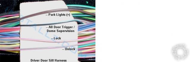
large wire harness with 40+ wires, with several the same color combination, will be impossible without a DMM.
Here is an example from a Ford F-150 of a typical wire harness...
A few answers to your questions.
H3/3 is connected to the Malibu's Orange ACC1 wire. As you discovered, there is also a Brown ( ACC2 ) wire. That
wire and this issue have been mentioned many times on this Forum. Here are the two basic thoughts on the Brown
ACC2 wire.
1. It is not absolutely necessary for a remote start install.
A. The vehicle will remote start OK and will not cause any CEL's or damage to the vehicle with it not powered.
B. The Brown wire only powers non-essential items ( like the radio, wipers, power windows, etc ). The Orange
ACC1 wire powers the Heater and A/C circuits that are desired during a remote start.
C. It requires an extra relay and fuses that cost money and consume time during the install.
2. It is best to fully duplicate all normal functions that a regular key start does.
A. Powering the Brown ACC2 wire will ensure that the vehicle is completely fooled into thinking a key was
used to start the engine.
The choice is yours. Both have their own advantages and disadvantages. Your 4206 has a Flex relay output that is
already being used to power IGN2 during a remote start. If you choose to power the Brown ACC2 wire, you will use
the H2/22 Orange (-) Accessory Output wire to control an extra 30/40 Amp SPDT relay that will supply power to this
Brown ACC2 wire.
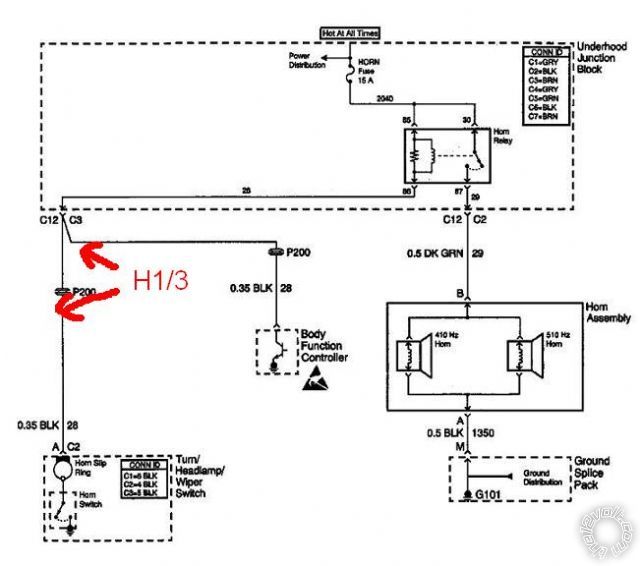
H1/3 Horn wiring. The horn diagram you found / posted shows a BLK ( Black ) wire going from the horn button on
the steering wheel, through the slip ring and leaving the multi-function switch connector at C2. I believe that is the
wire that I incorrectly listed above as "Black @ Ignition switch harness". An error on my part, it should have said
"Black @ steering column". Sorry for the confusion, I was going fast and cutting & pasting.
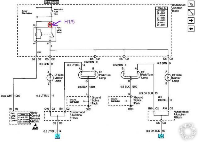
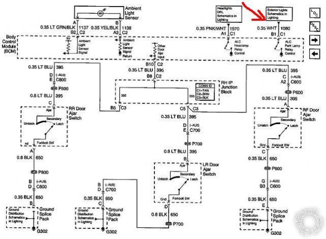
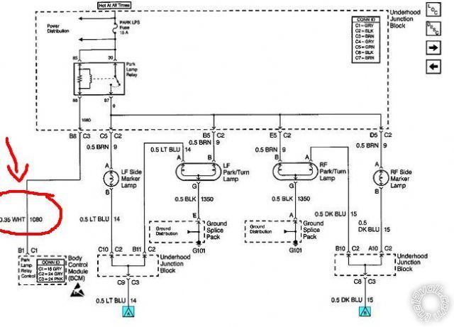
H1/5 Parking Light connection. It looks like the first diagram posted covers only the Headlight function of the switch.
The second diagram shows the Parking Lights after the BCM. Is there another diagram that details the Parking Light
control switch circuit? While I believe that the Brown (+) Parking Light wire is the best and easiest wire to locate and
connect to, there is a White (-) Parking Light control wire as noted by this info from Bulldog Security :
PARKING LIGHTS ( - ) WHITE (-) @ BCM, BEHIND PASSENGER SIDE OF THE DASH This is the wire shown in the
second diagram at the BCM. However, while Bulldog does not mention it, this White (-) Parking Light wire might have
to be relay isolated from the BCM to prevent damage to the BCM, but I am not positive about this.
-------------
Soldering is fun!
Posted By: weaz4200
Date Posted: November 16, 2013 at 1:52 PM
So, All is taken into account.
As far as the H3/3 wire dilema I had, it was due to 1 thing which is how the diagrams are labled. Look at the Ignition C1 and C2 connectors...
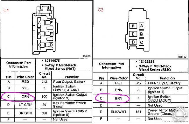
Note C1 cavity C Orange, Ign switch out (ignition 3) were as C2 cavity C Brown is also Ign switch out but labeled ACCY. Hence my confusion since the install guide states (+) ACC out.
Now, I'll admit that I'm not great with wiring. I can work with whats there but when it comes to fully understanding or adding something new then I'm a bit iffy.
Prime example is your #1 and #2 statements. I dont understand the conclusion of extra relay and fuses. How can I understand this? I mean I'd like to understand how to look at a circuit and be able to tell, like in this instance of orange vs brown, which would be a better choice and actually comprehend how and why.
So I'm set then on location of H1/3 Horn wiring.
As far as the H1/5 parking light connection... I stayed up late and must have been euphoric and missed them... I believe these 2 should help...
Got a few things I'd like to ask but it'll have to wait till later. Don't want too much clutter at one time.
THANKS,
ROB
Posted By: kreg357
Date Posted: November 16, 2013 at 3:02 PM
On the Brown ACC2 wire.
The IGN3 label applied to the Orange wire that we are calling ACC1, is one of those industry specific terms that can
sometimes have several meanings. Basically, in this case it means that the Orange wire has power when the key
is in the Ignition position only. It does not have power with the key in the Accessory position ( the Heat, fans and
A/C does not function ) and unlike a normal "Ignition" type wire, it looses power when the key is in the Start position
( less drag on the battery ). The Brown wire is more of a typical Accessory type wire, because it has power in the
Accessory and On positions, but not in the Start position.
As mentioned previously, I believe you can go with Option 1 above and leave the Brown wire "not used" for the R/S
install. If you choose to go with Option 2 and power it during the remote start run time, you will need a 30/40 Amp
Bosch style SPDT relay and 20 Amp fuse. Here is the relay wiring :
Relay Pin 85 to Viper H2/22 Orange (-) Accessory Output
Relay Pins 86 and 87 to Malibu +12V constant through 20 Amp fuse
Relay Pin 30 to Malibu Brown ACC2 wire @ ignition switch harness
Relay Pin 87a not used
Parking Lights :
Still think there is a wiring diagram for the Dash Light Switch that details the Parking Light function, similar to the
diagram you posted earlier with the Headlight function shown. Anyway, there should be a Brown wire that tests as
a (+) Parking Light wire at the headlight switch connector. Here is a video on replacing the switch assy and the
Brown wire should be found in the connector on the lower left ( driver's ) side.
https://www.youtube.com/watch?v=pR8NmTJ3QVI Here is another possible location for the Brown (+) Parking Light
wire, shown in this picture of the lower Passenger Kick Panel :

-------------
Soldering is fun!
Posted By: weaz4200
Date Posted: November 17, 2013 at 7:35 PM
Either way... Just a quick recap...
Remote Start harness (H3), 8-pin connector
H3/1 PINK - (+) IGNITION 1 INPUT/OUTPUT (Pink @ ignswitch) (C2/PIN B)
H3/2 RED / WHITE - +12V FUSED (30A) (Red @ ignswitch) (C2/PIN A)
H3/3 ORANGE - (+) ACCESSORY OUTPUT (Orange @ ignswitch) (C1/PIN C)
H3/4 VIOLET- (+) STARTER OUTPUT (Yellow @ ignswitch) (C1/PIN B)
H3/5 RED - +12V FUSED (30A) IGNITION 1 INPUT Red @ ignswitch) (C2/PIN A)
H3/6 PINK/WHITE - FLEX RELAY OUTPUT ***set for IGN2 Green @ ignswitch) ( C1/ PIN E)
H3/8 RED / BLACK - +12V FUSED (30A) ACC/STARTER INPUT Red @ ignswitch) (C2/PIN A)
Main Harness (H1), 6-pin connector
H1/1 RED (+)12VDC CONSTANT INPUT (Red @ ignswitch) (C2/PIN A)
H1/2 BLACK (-) CHASSIS GROUND (Chas Ground) (Chassis Ground)
H1/3 BROWN (-) 200mA HORN HONK OUTPUT (Black @ headlmp switch) (C2/PIN A)
H1/5 WHITE PIN 30 of LIGHT FLASH RELAY ***Set for (+) (Brown @ headlmp Switch) C2/PIN A)
Door Lock, 3-pin connector
1 BLUE (-) 500mA UNLOCK OUTPUT - To 451M door lock module
3 GREEN (-) 500mA LOCK OUTPUT - To 451M door lock module
Will order and wire up door locks with this... 451M
H2/2 BLACK/ WHITE (-) NEUTRAL SAFETY INPUT Chassis ground ( if auto trans ) (Chassis Ground)
H2/5 RED / WHITE (-) 200mA TRUNK RELEASE OUTPUT To Pin 85 of relay **
H2/9 DARK BLUE (-) 200mA STATUS OUTPUT bypass module GWR
H2/16 BROWN (+) BRAKE SHUTDOWN INPUT Light Blue @ Brake Pedal Switch (C1/C2/C3 Circuit 1134)
H2/17 GRAY (-) HOOD PIN INPUT (NC OR NO)to supplied hood pin ??? (PURPOSE?) (No start with hood open?)
H2/23 VIOLET/WHITE TACHOMETER INPUT see note 1 (circuit 121/ wht wire/ PIN A2)
Trunk release - Will get a 30/40 Amp SPDT relay w/ 10 Amp fuse and wire up as previously suggested.
Bypass module - Xpress Kit PLJX
Look good? Thumbs up?
Thanks,
ROB
Posted By: kreg357
Date Posted: November 17, 2013 at 8:02 PM
Rob,
Looks good. A few notes :
1. The Hood Pin Switch is an important safety feature. It prevents the remote start from working if the hood
is open and will shutdown the engine if the hood is raised while running under a remote start.
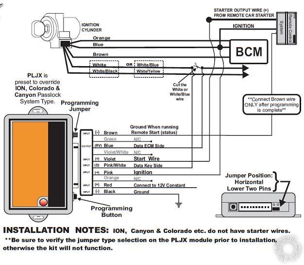
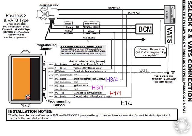
2. The PLJX install manual is a little difficult to follow. Go with the PASSLOCK 2 & VATS CONNECTION diagram
but remember that VATS info is on there, too. The PLJX connections for IGN and Starter can be connected at
the corresponding wires on the H3 harness and the power & ground can be piggy-backed to the 4206's power
and ground wires.
-------------
Soldering is fun!
Posted By: weaz4200
Date Posted: November 17, 2013 at 8:34 PM
I assume your saying its a bit difficult to follow because it shows 5 wires at the key cylinder instead of 2 wires like the GM Passlock 2 bypass like you posted on the previous page?
I mean here's the wiring on the PLJX...
Posted By: weaz4200
Date Posted: November 17, 2013 at 8:48 PM
Posted By: kreg357
Date Posted: November 17, 2013 at 8:53 PM
-------------
Soldering is fun!
Posted By: weaz4200
Date Posted: November 17, 2013 at 9:03 PM
Question - Regardless of passlock bypass that I buy, are they all gonna be that in depth or is there a bypass module less complicated? Just curious.
Posted By: kreg357
Date Posted: November 17, 2013 at 9:21 PM
All of the bypass modules for that vehicle have pretty much the same wiring. Some of the older bypass modules did cut the Passlock2 wire. It's just that the install guide for the PLJX is so poorly written.
Take a look at this iDatalink install guide for the ADS TBSL PL. The 2000 Malibu is Type 3 on Page 7.
https://cdncontent2.idatalink.com/corporate/Content/Manuals/TB-PL/ADS-TBSL-PL_20110120.pdf
Very concise and clearly written plus the programming is very easy. Plus there is a lot of good basic
Passlock2 info at the beginning of the guide.
From this iDatalink guide, you now know that the Keysense wire connection is not necessary. 
-------------
Soldering is fun!
Posted By: weaz4200
Date Posted: November 17, 2013 at 9:27 PM
Posted By: weaz4200
Date Posted: November 17, 2013 at 9:36 PM
Posted By: kreg357
Date Posted: November 17, 2013 at 9:43 PM

-------------
Soldering is fun!
Posted By: weaz4200
Date Posted: November 17, 2013 at 9:47 PM
Posted By: weaz4200
Date Posted: November 17, 2013 at 10:32 PM
Posted By: kreg357
Date Posted: November 18, 2013 at 5:40 AM
-------------
Soldering is fun!
Posted By: weaz4200
Date Posted: November 18, 2013 at 3:29 PM
Was hoping you could help me understand the trunk release diagram...
The relay will be wired as you stated...
** The Trunk Release Output is (-) and the Malibu needs a (+) signal. Use a 30/40 Amp SPDT relay w/ 10 Amp fuse
as shown below :
Relay Pin 85 to H2/5
Relay Pin 86 & 87 to +12V constant through 10 Amp fuse (((H1/1 RED (+)12VDC CONSTANT INPUT (Red @ ignswitch) (C2/PIN A) )))
Relay Pin 30 to Malibu BLACK/ WHITE (+) @ TRUNK RELEASE SWITCH
Relay Pin 87a not used
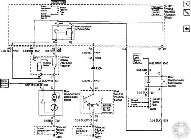
So looking at the diagram.
Theres 12V+ at the 87 and 86 pin of the Rear Compartment Lid release relay.
The splice at 1040 goes all the way through the Lid release switch on the right comes around to the 86 pin on the Lid release relay. The coil between 86/85 only gets energized when the Park neutral position switch is in Park or Neutral. So once the Lid release Relay coil is energized the switch portion on the release relay closes and 12V+ flows through 87 to 30 and then down to the Remote Control Door Lock Reciever.
ORG 1040 has 12V+ and "M" is getting ground from G102 after the Park Neutral Position switch.
Then I'm stuck. How does the rest of the circuit work?
Posted By: kreg357
Date Posted: November 18, 2013 at 7:02 PM
that has a Trunk Release button on it. The "relay" shown in the Remote Control Door Lock Receiver is normally in
the position shown and pressing the Rear Compartment Lid Release Switch ( with the trans in Park or Neutral ) will
get +12V to the Rear Compartment Lid Release Motor. What is not shown is that when you press the Factory FOB
Trunk Release button that "relay" will energize ( if trans is in Park or Neutral ) and supply +12V to the Rear Compartment
Lid Release Motor.
-------------
Soldering is fun!
Posted By: weaz4200
Date Posted: November 18, 2013 at 7:31 PM
So what I need to do with the Relay I get is wire PIN 30 and splice into the BLK/WHT wire (circuit 56) between the Remote control door lock reciever and the Lid release motor. Correct?
Posted By: weaz4200
Date Posted: November 18, 2013 at 7:45 PM
Posted By: weaz4200
Date Posted: November 21, 2013 at 12:24 PM
Looks like I'm not using the WHITE/ black and the BROWN / black wires...
1) Does the 3 pin plug on the 451M get plugged into the python module?
2) How do I distinguish, from the Malibu's door lock schematic whether I use Dia A or Dia B?
Thanks,
ROB
Posted By: kreg357
Date Posted: November 21, 2013 at 8:19 PM
There appears to be differences between the Bulldog Security and Audiovox wire guides ( not unusual ). One
says BLACK/ White and the other says Black for the Trunk Release wire at the switch. Your wire diagrams also
says Black. That will probably be the correct answer, but as per S.O.P., use a DMM to verify. So the updated
relay wiring will probably be like this :
Relay Pin 85 to H2/5
Relay Pin 86 & 87 to +12V constant through 10 Amp fuse (((H1/1 RED (+)12VDC CONSTANT INPUT (Red @ ignswitch) (C2/PIN A) )))
Relay Pin 30 to Malibu BLACK (+) @ TRUNK RELEASE SWITCH
Relay Pin 87a not used
On the 451M, you will plug it right into the Python 4206 door lock port. The correct diagram is the Type A. Yes,
the WHITE/ Black and BROWN / Black wires will not be used. Additionally, you can connect the Violet fused wire to any
convenient +12V constant source ( that can handle 15 Amps ).
-------------
Soldering is fun!
Posted By: weaz4200
Date Posted: November 21, 2013 at 9:27 PM
I guess I'm down to my final questions on the wiring.
Seeing as I will be running all the 12+ constants through the (red@ignition) (c2/PIN A)... That's not gonna be a problem? Like too much on that one circuit? This includes the Violet fused wire as well.
Also, are there any other wires I need to add fuses to?
I know you stated 10 Amp fuse for the Relay Pin 86 & 87 for trunk release so I still have to pick up a fuse holder and wire it up with the relay.
BUT
The wiring for the PLJX is not fused on the 12+ constant. Should I add a fuse to it?
THANKS VERY MUCH,
ROB
Posted By: kreg357
Date Posted: November 21, 2013 at 10:02 PM
RED / Black perhaps. You can split the load up between these two wires. The PLJX bypass module draws very little
current and really doesn't need a fuse. It is OK to connect its' power wire to one of the Pythons's thick +12V constant
wires ( like H1/1 ) after the fuse.
-------------
Soldering is fun!
Posted By: weaz4200
Date Posted: November 21, 2013 at 11:29 PM
Thanks,
ROB
Posted By: weaz4200
Date Posted: November 23, 2013 at 8:20 PM
H2/5 RED / WHITE (-) 200mA TRUNK RELEASE OUTPUT To Pin 85 of relay **
H2/16 BROWN (+) BRAKE SHUTDOWN INPUT Light Blue @ Brake Pedal Switch (C1/C2/C3 Circuit 1134)
H2/17 GRAY (-) HOOD PIN INPUT (NC OR NO) to supplied hood pin ????????????? (PURPOSE?)
This is what I did.
Got all wires hooked up... except the ones listed above and the H2/9 blue to PLJX brown...
I programmed the PLJX via the instructions THEN I plugged in the 4206P and then connected the h2/9 to pljx..
Went through and learned the tach. I believe that went as it was supposed to.
Then remote pairing, followed to a "T" and all went as instructed.
Car wont remote start. I tried to run the diagnostic... and it blinked "7 times"... Timer mode/Turbo mode/ Manual mode error.
I'm not sure what's up.
Thanks,
ROB
Posted By: weaz4200
Date Posted: November 23, 2013 at 9:29 PM
The car tries to start for a second... Does it a few times... Like on the 3rd or 4th try it pops the trunk (how the trunk pops I dont know, as it is not wired up)... Antitheft light is blinking... (insert shaking head in anger here).
Not sure what to do next.
Posted By: weaz4200
Date Posted: November 23, 2013 at 10:44 PM
Went ahead and disconnected the brown wire from bypass/blue wire from 4206p. Did a reprogram on the PLJX. Not sure if I just didnt program the PLJX properly the first time or if I was supposed to to have the 4206p hooked up as well minus the H2/9 blue to PLJX brown (4206p not hooked up first time/only had PLJX hooked up) but all seems to work for now.
Not sure why before the trunk was popping after trying to start multiple times with no success. Maybe someone can explain what was happening.
I feel I might need to get a battery or maybe this one just needs to recharge a bit since I did use the mirror lights on and off during the install.
Either way. Car starts and runs fine.
Still have to wire up the H2/16 BROWN (+) BRAKE SHUTDOWN INPUT Light Blue @ Brake Pedal Switch (C1/C2/C3 Circuit 1134)
and
H2/17 GRAY (-) HOOD PIN INPUT
But I cant seem to find the LT BLUE wire at the brake pedal.
Posted By: weaz4200
Date Posted: November 24, 2013 at 7:10 PM
Purchased a new battery as I figured the old battery would attribute to the remote start not wanting to start ever so often.
So 1 of 3 things happens..
1) Remote starts car fine and all is good (obviously not a problem here)
2) Tries to start 1 time and doesn't start... Lights/dash stay on... (i'll usually initiate shutdown on the remote control after about 5-6 seconds if it doesn't try to start again)
3) Tries to start and fails. Attempts to start again, fails... Like 3rd or 4th time it pops the trunk.
Why would 2 or 3 be happening? More importantly why does it only try once and not again and why #3 does it try a few times then pops the trunk?
I started multiple times with the old battery earlier in the day no problem... Though just like last night once it gets dark and REAL COLD it acts stupid.
Posted By: kreg357
Date Posted: November 24, 2013 at 7:49 PM
A few thoughts :
1. Ensure that all connections are well soldered and properly insulated.
2. As mentioned previously, the R/S's chassis ground wire should have a soldered on terminal ring and be bolted to a
good chassis ground point.
3. Were you having start-up problems before ( due to the Passlock2 ) ? The PLJX "learns" the Passlock2 value during
programming, so if that is off and / or the wire connections aren't perfect, it could account for your engine start-up
problems. Are you getting any "Security" type dash lights during the failed start attempts?
4. As you found out, programming the R/S with the remotes is tricky. Due to the failed start-ups and re-tries, I would
verify that the R/S is in Tach Mode and re-learn the Tach signal. Another thought, does the Malibu have "one-touch"
starting? That is where the car will continue to crank the starter motor and get the engine running with just a quick
turn and release of the key to the START position. If it does, you could program the R/S for a fixed crank time and let
the car do the rest. Also, check the R/S's shutdown diagnostic for a reason / code for the failed remote start attempt.
-------------
Soldering is fun!
Posted By: weaz4200
Date Posted: November 24, 2013 at 9:16 PM
I am certain all connections are solid as I made sure to check each one after I wired them up one by one. I will check again though. Insulation wise, I probably used more insulation then I should, but I wanted to be certain there was no shorts anywhere.
Terminal ring was used. I verified chassis ground in multiple places on the chassis to make certain I had a good connection. All seems golden. Will check again.
As stated previously, what happened yesterday was....
I initially programed the PLJX without having the 4206p installed. (I had all wiring run for the 4206p just didn't plug it in yet) After I attempted to program the PLJX I plugged in the 4206p and then also connected the 4206 blue/PLJX brown as I believe I had programed the Passlock correctly. Then I proceeded to learn the tach. Then programed the remotes/fabs.
Once I believed I had everything programmed I went ahead and attempted to remote start the car. All that happened was I encountered "7 Blinks" from the marker lights. From the diagnostic that had something to do with "manual mode enabled". So I went through the menus and changed from manual trans to auto.
Once I fixed that I again attempted to remote start. It tried to start but did not. A couple seconds go by and it tries to start again. Typically when I initiated remote start it would try to start like 3 or 4 times. If it did not start by the 3rd or 4th try in the sequence it would pop the trunk... Then I believe it stops trying to start.
I tried a few more times and then eventually I encountered the THEFT light... So I attempted to start the car via the regular key. No dice. Wouldn't start that way either
So I went ahead and disconnected the battery. Waited a bit then plugged back in. Once theft light was gone I started the car via the regular key. Once that worked I reprogrammed the PLJX. This time around I had the 4206p fully connected, just unplugged the blue 4206/brown PLJX wire. After it was programmed this time I connected the blue/brown wire again.
At this point the battery seemed a bit low so I threw a battery charger on it and waited. Once the battery charged a bit I went ahead and remote started the car.
All seems fine. It starts no problem a few times. Plus its also 15 degrees outside so its kinda starting slow. So I called it a night.
So I go back today and remote start. Starts up multiple times no problem. I finished wiring up the brake switch and trunk release.
By this time its about 4pm and temps are at 20ish degrees. Battery seems weak as I try to start via the key. Slow start. So I went to get a new battery as the old one is 3 years old already.
Plug in the new battery and start the car with key. Then I attempt to start once (starter cranks a few times then stops) Does not continue. I shut down remote start. I try again. Now it starts.
Since the new battery was installed I tried starting a few times and no problem. I just started it 2 times from inside the house and no problem.
So, I'm not sure. Maybe its fine now. Guess I'll watch it and see if it happens again. If it encounter the no start/ trunk pop or no start (cranks once then stops) I'll let you know.
I believe its in tach mode as it starts and runs for now. I will check again though. If it wasn't in tach mode wouldn't it not start and stay running like it is now?
Malibu does not have one touch.
I can check the shutdown diagnostic. Is the code stored for a while or no? I mean, if I try to start and it doesn't then it eventually starts is the code still stored or is it cleared.
Posted By: weaz4200
Date Posted: November 24, 2013 at 9:28 PM
1st attempt - Start no problem.
Wait about 30 seconds.
2nd attempt - remote start initiates and cranks once. Then stops. Lights stay on. No more crank. I initiate shut down.
Wait 30 seconds.
3rd attempt - Cars start no problem.
Now I don't know how much weather is a factor.... Plus one other thing I'm thinking... Maybe I'm just crazy but it seems like with the times that there's a no start I cant hear the fuel pump... Maybe its just in my head.
Posted By: kreg357
Date Posted: November 24, 2013 at 11:25 PM
I tried a few more times and then eventually I encountered the THEFT light... So I attempted to start the car via the regular key. No dice. Wouldn't start that way either
This is indicative of "Passlock2 short tamper mode". This is what happens if the bypass is not programmed properly and you try several remote start attempts.
Now I don't know how much weather is a factor.... Plus one other thing I'm thinking... Maybe I'm just crazy but it seems like with the times that there's a no start I cant hear the fuel pump... Maybe its just in my head.
Passlock2 actually controls the vehicles fuel pump. When the Passlock2 is not bypassed, the engine will crank and even fire / stumble briefly when it uses up any fuel remaining in the rail ( plus the dash Theft light will be on ).
Yes, the shutdown diagnostics code will be stored from the last remote start failure and can be checked at any time.
-------------
Soldering is fun!
Posted By: weaz4200
Date Posted: November 24, 2013 at 11:51 PM
But if there was a passlock issue why does is start and run no problem certain times?
Posted By: weaz4200
Date Posted: November 25, 2013 at 12:06 AM
A lot of 4 flashes - Transmitter shut down and 5 flashes brake shutdown... I assume 4 flashes comes from me putting in the key after remote start and the remote start shuts down and the key takes it's place. I also assume the 5 flashes come from me testing it out earlier when I was wiring up the brake switch. I tested it by depressing the brake pedal to make sure the car would shutdown.
Though I did get 3 flashes - Low or no RPM. Maybe I need to increase cranking time?