2001 lexus is300 viper 5704v
Printed From: the12volt.com
Forum Name: Car Security and Convenience
Forum Discription: Car Alarms, Keyless Entries, Remote Starters, Immobilizer Bypasses, Sensors, Door Locks, Window Modules, Heated Mirrors, Heated Seats, etc.
URL: https://www.the12volt.com/installbay/forum_posts.asp?tid=135365
Printed Date: April 07, 2026 at 11:31 AM
Topic: 2001 lexus is300 viper 5704v
Posted By: ward1722
Subject: 2001 lexus is300 viper 5704v
Date Posted: November 24, 2013 at 5:58 PM
What is the best way to hook uo the door lock and unlock. I don't mind if all doors unlock at the same time.
Replies:
Posted By: triniforever
Date Posted: November 24, 2013 at 6:17 PM
On that car you need to look at DEI tech tip 1070 Toyota/Lexus door lock interface .A relay and two diodes are required. Bulldog security has the tech you need document you need and it's free to access.
-------------
triniforever
Posted By: ward1722
Date Posted: November 24, 2013 at 6:24 PM
I have that document and the relay and two diodes.
I'm not sure what wire it is saying to hook the second diode to in the door tha t goes to the door ecu in the diagram.
Thanks
Posted By: triniforever
Date Posted: November 24, 2013 at 7:25 PM
To find those wires you need to go inside the drivers door panel it's on the master switch I believe , look at the document it should tell you what color wires you need for your car.the door ECU is also inside the drivers door if Im not mistaken
-------------
triniforever
Posted By: yellow_cake
Date Posted: November 26, 2013 at 8:55 PM
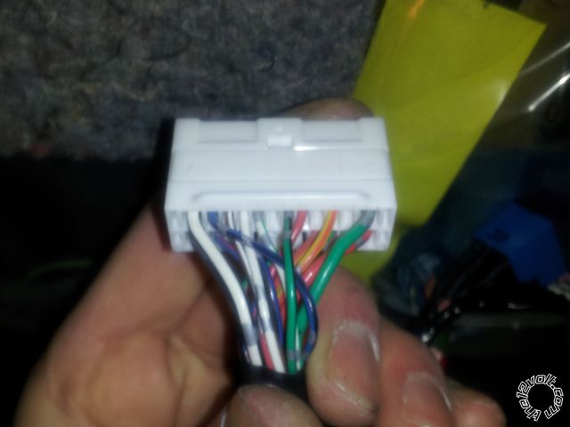
As triniforever states, the 3 wires are all coming from the driver's door switch.
There is only one GREEN/ red (lock) and GREEN/ black (unlock) colored wires. However there are more than one blue/black colored wires so you need to test each to find the lock detection wire.
Test using the key in the door lock cylinder, make sure the door switch module is plugged as well.
The lock wire will show ground when the key is turned to the lock position; unlock wire will show ground in the unlock position; the lock detection wire will also show ground in the unlock position if I'm not mistaken.
It doesn't matter which side of the relay you attach the 2nd diode to for the lock detection wire. That relay will only interrupt that wire during locking, so it will get the pulse from the unlock no matter which side you connect to.
IS300 driver's door switch harness connector:
Posted By: ward1722
Date Posted: November 28, 2013 at 8:02 AM
I got them hooked up and works great and to figure out which blue black wire to use I looked at my door unlock and lock wires and they have two silver dots on them from factory so I looked at the blue black wires and one of them had two silver dots and that was it.
Posted By: ward1722
Date Posted: November 29, 2013 at 7:50 PM
Is there anything special with hooking up the remote start or anything extra you need for it to work.
How do you get the park lights to work I've tryed hooking it to the red wire going to the harness going to the switch but it doesn't work
Posted By: yellow_cake
Date Posted: November 30, 2013 at 1:56 PM
Nothing extra, straight forward assuming it's an automatic.
The red wire at the headlight switch is a negative trigger. First make sure you have the right wire by testing with a digital multimeter. 2nd make sure you are using a (-) parking lights output from your remote starter.
You will need a bypass module such as an Xpresskit PKALL, Fortin KeyOverrideAll, etc.
You have 2 ignition wires so you will have to use a relay for the 2nd one if your remote starter doesn't have a 2nd ignition wire/flex relay.
You'll need to feed the key sense wire from the status output (ground while running) to disarm the alarm during remote start without unlocking the doors.
Aside from that it's very easy, tach wire it at the ignitor on the driver's strut tower, hood switch you can wire into the factory switch...
Posted By: ward1722
Date Posted: November 30, 2013 at 4:51 PM
do I cut tye ignition two wire and connect the pink/white ign2/flex relay output and the pink/black flex relay input 87a key side (if required) of flex relay
Posted By: yellow_cake
Date Posted: November 30, 2013 at 6:06 PM
Do not cut the ignition 2 wire..
H3/1 Pink -- to ignition 1 (BLACK/ red)
H3/2 RED / White -- to +12v constant (white or WHITE/ red)
H3/3 Orange -- to accessory (red)
H3/4 Violet -- to starter (BLACK/ white)
H3/5 Red -- to +12v constant (white or WHITE/ red)
H3/6 Pink/White -- to ignition 2 (blue/red)
H3/7 Pink/Black -- Not connected
H3/8 RED / Black -- to +12v constant (white or WHITE/ red)
Also if you don't want the autolights to come on during remote start, the wire color is GREEN/ YELLOW in the headlight switch harness you can interrupt this wire during remote start.
Posted By: ward1722
Date Posted: November 30, 2013 at 7:55 PM
I hooked it up that way but it tells me remote start error on the remote
Posted By: yellow_cake
Date Posted: December 01, 2013 at 12:24 AM
What us the error you are getting, ie how many light flashes?
Btw, the neutral safety input wire has to connect to ground and the neutral safety switch has to be plugged in and in the on position.
Posted By: ward1722
Date Posted: December 01, 2013 at 1:31 PM
Its 7 flashes (manual transmission mode is enabled and not initialized)
Posted By: ward1722
Date Posted: December 01, 2013 at 1:50 PM
Do I need to hook up the 200ma ignition and starter wires on the 24 pin harness and if so where do I hook them too
Posted By: yellow_cake
Date Posted: December 01, 2013 at 3:13 PM
The viper units come from the factory in manual transmission mode. You have to go into programming and change it to automatic mode.
The 200ma ignition wires are not needed for your car.
Posted By: ward1722
Date Posted: December 01, 2013 at 4:15 PM
Do i use the control button on the antenna to program it
Posted By: yellow_cake
Date Posted: December 01, 2013 at 4:48 PM
Yes, follow the instructions of the install guide.
Posted By: ward1722
Date Posted: December 01, 2013 at 8:26 PM
Got it programmed works great and now I just have to put in the extra sensors I got
Thanks for the help and information
|