python 4206p r/s in 2006 f 150
Printed From: the12volt.com
Forum Name: Car Security and Convenience
Forum Discription: Car Alarms, Keyless Entries, Remote Starters, Immobilizer Bypasses, Sensors, Door Locks, Window Modules, Heated Mirrors, Heated Seats, etc.
URL: https://www.the12volt.com/installbay/forum_posts.asp?tid=135824
Printed Date: May 11, 2026 at 8:40 PM
Topic: python 4206p r/s in 2006 f 150
Posted By: highflyer2488
Subject: python 4206p r/s in 2006 f 150
Date Posted: January 13, 2014 at 8:36 PM
Hi everyone,
I'm newly registered to this forum, but I've done hours of browsing trying to learn as much as I can. Go easy on me 
Alright, I've been gathering as much info as I can for my particular install before I even think about starting. Thanks to this site, I have acquired the appropriate wiring table for my truck. Also, I learned that the directed 1100F is the better immobilizer bypass module for my truck. I wasn't able to find a install pictorial for my year of truck. Maybe there is one that applies to my truck of which I am unaware?
I have experience with car audio, but I have never tampered with remote start units. I could have a unit installed for me, but I'd much rather learn something new during the process.
My questions would be: what is a good remote start unit that is easily programmed, has a 2000 ft or more range, two way, good remote battery life, all for the low 100 dollar price range? I found the python 4206p sold on Amazon for about 115. Anybody have other recommendations?
Also, for my particular truck, is there any additional hardware I'll need to do it right (and safely)? (Diodes for BCM? Extra inline fuses and whatever else)
As someone who has never installed one before, I'd like to dive in with all of the necessary tools and hardware. Any heads up or gotchyas would be much, much appreciated.
Thanks!
Replies:
Posted By: kreg357
Date Posted: January 13, 2014 at 8:54 PM
Hi and welcome to the 12 Volt!
For the money, you can't beat the 1100F bypass module. There should be an install guide in the Downloads section. The guide
I have does list your truck. You can go to the iDatalink WEB site, look up your truck and use the AS TBSL TI install guide to get
the transponder connector type, location, wire colors and pin numbers.
If I remember correctly, the hardest part of that truck ( 2004 - 2007 are the same ) is finding the Lock and Unlock wires. They are
in a bundle of about 100 wires in the drivers door sill heading towards the rear of the truck.
If you are just doing a remote start with keyless entry on a F150 gas engine with power locks, there isn't anything else you need
other than the R/S and the bypass. I would suggest getting a mercury tilt switch and using that instead of the kit supplied pin
switch. No holes to drill and they last a lot longer.
Finding a quality long range, two-way R/S w/keyless entry system for $100 will be a challenge. Stick with a well known brand and
you will be fine. ------------- Soldering is fun!
Posted By: highflyer2488
Date Posted: January 13, 2014 at 9:29 PM
Thanks for the info!
So really a person is only concerned with the BCM if installing an alarm unit, right? I'm sure I'll have fun hunting down those door unlock wires.
What do you recommend for wire testing? This may a dumb question, but is it effective to use A DMM for testing through wire shielding or is it best to get a probe with a light for that situation? I can imagine looking for voltage on the door wires without a pin connector in site to touch would be a pain using a DMM...
Mercury tilt sensor sounds like a good idea. Just for my own knowledge, how are those affected by driving or being parked on a steep incline?
Thanks again!
Posted By: kreg357
Date Posted: January 13, 2014 at 9:57 PM
For checking wires like ignition, door triggers and locks, I use a LED test probe. It draws a mere 3mA so it is very computer friendly. You can see it in use and get more info in this Pictorial : https://www.the12volt.com/installbay/forum_posts.asp?tid=133496&tpn=1&PN=1 Bulldog Security remote starter kits include a cute LED test probe. They draw 17mA but are very handy.
I usually try to make the R/S's connections in the drivers dash / kick panel area. The BCM on that truck is on the drivers side rear cabin wall, I think.
Mercury switches aren't good for alarm installs due to the amount the hood has to be raised before it will trigger. As you pointed out, using them for the hood pin on a remote start install in Pittsburgh or San Francisco wouldn't be a good idea, either. I usually adjust them to trigger when the hood is about 2/3's open. That will allow proper operation when parked on normal slopes.
Think if you do some searches on that model/series truck, you will find a picture of the door lock wires. Still have to test, though. Wait, I found it!
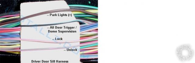
------------- Soldering is fun!
Posted By: highflyer2488
Date Posted: January 13, 2014 at 10:09 PM
Awesome. I appreciate your time. I'll keep this posted on how everything goes.
Posted By: smokeman1
Date Posted: January 16, 2014 at 6:31 AM
Link to a youtube video of the basic wiring for a remote start.
The video shows lights being energized to simulate the vehicles Ignition, Accessory, and Starter circuits.
As well as parking lights, dome light, and a relay activated with the 200mA circuit.
https://youtu.be/uq1ETQxMp7M
-------------
When all else fails, Read the Instructions
Support the12volt.com Make a Donation
Posted By: highflyer2488
Date Posted: January 16, 2014 at 10:57 AM
Thanks! That's a great video.
Posted By: highflyer2488
Date Posted: January 20, 2014 at 9:49 PM
I've been working through the wiring template for my install. Here is what I have so far...
Vehicle Information: 2006 Ford F-150 XLT 5.4L
Alarm / Remote Start Unit: Python 4206P
Bypass Module: Directed 1100F
Alarm / Remote Start / Bypass Unit Vehicle
Connection Color Description Color Polarity Location:
H1/1 RED (+)12VDC CONSTANT INPUT +
H1/2 BLACK (-) CHASSIS GROUND - Any good ground point on Chassis
H1/3 BROWN (-) 200mA HORN HONK OUTPUT NA?
H1/4 WHITE/ BROWN LIGHT FLASH ISOLATION WIRE - PIN 87a light flash relay Brown Park light wire? + Headlight switch or harness in door sill
H1/5 WHITE PIN 30 of LIGHT FLASH RELAY Brown Park light wire? + Headlight switch or harness in door sill
H1/6 ORANGE 500 mA GROUND WHEN ARMED OUTPUT NA
H2/1 PNK/WHITE (-) 200mA FLEX RELAY CONTROL OUTPUT NA
H2/2 BLACK/ WHITE (-) NEUTRAL SAFETY INPUT Grounded? Ive seen in a couple threads that this is not necessary. True?
H2/3 BLUE/WHITE (-) 200mA 2ND STATUS /REAR DEFOGGER OUTPUT NA
H2/4 GREEN/ BLACK (-) 200mA FACTORY ALARM DISARM OUTPUT NA
H2/5 RED / WHITE (-) 200mA TRUNK RELEASE OUTPUT NA
H2/6 GREEN (-) DOOR INPUT** NA
H2/7 BLACK / YELLOW (-) 200mA DOME LIGHT OUTPUT BLACK/ Light Blue + drivers kick panel, gray plug, pin 6
H2/8 EMPTY ------------------------------------ NA
H2/9 DARK BLUE (-) 200mA STATUS OUTPUT NA
H2/10 PINK (-) 200mA IGNITION 1 OUTPUT NA
H2/11 WHITE/ BLACK (-) 200mA AUX 3 OUTPUT NA
H2/12 VIOLET (+) DOOR INPUT NA
H2/13 WHITE/ VIOLET (-) 200mA AUX 1 OUTPUT NA
H2/14 VIOLET/BLACK (-) 200mA AUX 2 OUTPUT NA
H2/15 ORANGE / BLACK (-) 200mA AUX 4 OUTPUT NA
H2/16 BROWN (+) BRAKE SHUTDOWN INPUT Lt. Green + brake pedal switch
H2/17 GRAY (-) HOOD PIN INPUT (NC OR NO) Needed Run through firewall
H2/18 VIOLET / YELLOW (-) 200mA STARTER OUTPUT NA
H2/19 BLUE** FACTORY HORN INPUT (Use Jumper to set polarity) Dk Blue ** - steering column harness. Do I only need this for the "alarm" portion of the two way remote?
H2/20 GRAY/BLACK (-) DIESEL WAIT TO START INPUT NA
H2/21 WHITE/ BLUE ACTIVATION INPUT NA
H2/22 ORANGE (-) 200mA ACCESSORY OUTPUT NA
H2/23 VIOLET/WHITE TACHOMETER INPUT Not RED / lt green or red AC any ignition coil or fuel injector
H2/24 GREEN / WHITE (-) 200mA FACTORY ALARM ARM OUTPUT NA
H3/1 PINK (+) IGNITION 1 INPUT/OUTPUT Dark Blue/Light Green + Ign switch harness
H3/2 RED / WHITE +12V FUSED (30A) IGNITION 2/FLEX RELAY INPUT NA
H3/3 ORANGE (+) ACCESSORY OUTPUT BLACK/ Light Green + Ign switch harness
H3/4 VIOLET (+) STARTER OUTPUT RED / Light Blue + Ign switch harness
H3/5 RED +12V FUSED (30A) IGNITION 1 INPUT NA
H3/6 PINK/WHITE IGNITION 2/FLEX RELAY OUTPUT NA
H3/7 PINK/BLACK FLEX RELAY INPUT 87a (IF REQUIRED) OF FLEX RELAY NA
H3/8 RED / BLACK +12V FUSED (30A) ACCESSORY/STARTER INPUT Light GREEN/ Purple + Ignition switch harness
1 BLUE (-) 500mA UNLOCK OUTPUT Pink/Light Green Type B Drivers door boot/sill
2 EMPTY NOT USED NA
3 GREEN (-) 500mA LOCK OUTPUT Pink / YELLOW Type B Drivers door boot/sill
* The Normally Closed setting will only work if one of the vehicle's doors is connected. If more than one door is to be monitored, then it is recommended to use the Xpresskit DTIMAZDA or tech tip # 1921 on www.directechs.com to interface with these types of vehicles.
** This optional input can can be connected to the horn circuit (+ or -). When this wire receives an input for a minimum of .5 seconds, the system reports a trigger on the 2way remote. This is useful on vehicles that have a factory security system that can be armed/disarmed with our system. The system will not report that a zone has been triggered when unlocking with the remote and is not available with the 1-way re- mote.
------------------------------------------------------------
I have a feeling the formatting is not going to be so good....
I used this to get my wire colors and locations. Seems to be in line with all of the other ones I've seen.
Anyways, I am wondering about the horn trigger input H2/19. I am guessing this is an input to the brain when the horn is sounding so it can radio back to the two way remote notifying you the factory alarm is sounding?
What about H1/3. Is this connection necessary?
Also H2/2. What's up with this guy? I've seen some people have issues with this connection. Is it necessary? Does this have anything to do with the supplied neutral safety switch in my kit and do i need that installed?
I'm confused with the Main harness connections, specifically H1/4 and H1/5. Which one of these do I splice into the brown parking light wire?
Lasty, am I completely missing anything? I'm still waiting for the 1100F to come in the mail, so I'll have to figure out how all of that meshes into this.
Thanks for your help!
Posted By: kreg357
Date Posted: January 21, 2014 at 6:21 AM
A few updates...
Vehicle Information: 2006 Ford F-150 XLT 5.4L
Alarm / Remote Start Unit: Python 4206P
Bypass Module: Directed 1100F
Alarm / Remote Start / Bypass Unit Vehicle
Connection Color Description Color Polarity Location:
H1/1 RED (+)12VDC CONSTANT INPUT +12V constant Light GREEN/ Purple (+) @ Ignition switch harness
H1/2 BLACK (-) CHASSIS GROUND - Any good ground point on Chassis
H1/3 BROWN (-) 200mA HORN HONK OUTPUT NA
H1/4 WHITE/ BROWN LIGHT PIN 87a NA
H1/5 WHITE PIN 30 of LIGHT FLASH RELAY Brown Park light wire (+) Headlight switch or harness in door sill
H1/6 ORANGE 500 mA G W A OUTPUT NA
H2/1 PNK/WHITE (-) 200mA FLEX RELAY CONTROL OUTPUT NA
H2/2 BLACK/ WHITE (-) NEUTRAL SAFETY INPUT Grounded, if auto trans
H2/3 BLUE/WHITE (-) 200mA 2ND STATUS /REAR DEFOG OUTPUT NA
H2/4 GREEN/ BLACK (-) 200mA FACTORY ALARM DISARM OUTPUT NA
H2/5 RED / WHITE (-) 200mA TRUNK RELEASE OUTPUT NA
H2/6 GREEN (-) DOOR INPUT** NA
H2/7 BLACK / YELLOW (-) 200mA DOME LIGHT OUTPUT BLACK/ Light Blue + drivers kick panel, gray plug, pin 6
H2/8 EMPTY ------------------------------------ NA
H2/9 DARK BLUE (-) 200mA STATUS OUTPUT To 1100F, Blue/White GWR Input wire
H2/10 PINK (-) 200mA IGNITION 1 OUTPUT NA
H2/11 WHITE/ BLACK (-) 200mA AUX 3 OUTPUT NA
H2/12 VIOLET (+) DOOR INPUT NA
H2/13 WHITE/ VIOLET (-) 200mA AUX 1 OUTPUT NA
H2/14 VIOLET/BLACK (-) 200mA AUX 2 OUTPUT NA
H2/15 ORANGE / BLACK (-) 200mA AUX 4 OUTPUT NA
H2/16 BROWN (+) BRAKE SHUTDOWN INPUT Lt. Green (+) brake pedal switch
H2/17 GRAY (-) HOOD PIN INPUT (NC OR NO) Needed Run through firewall
H2/18 VIOLET / YELLOW (-) 200mA STARTER OUTPUT NA
H2/19 BLUE** FACTORY HORN INPUT (Use Jumper 2 set polarity) NA if the F150 does not have a Factory alarm ( H2/4 is NA )
H2/20 GRAY/BLACK (-) DIESEL WAIT TO START INPUT NA
H2/21 WHITE/ BLUE ACTIVATION INPUT NA
H2/22 ORANGE (-) 200mA ACCESSORY OUTPUT NA
H2/23 VIOLET/WHITE TACHOMETER INPUT Not RED / lt green or red (AC) any ignition coil or F.I.
H2/24 GREEN / WHITE (-) 200mA FACTORY ALARM ARM OUTPUT NA
H3/1 PINK (+) IGNITION 1 INPUT/OUTPUT Dark Blue/Light Green + Ign switch harness
H3/2 RED / WHITE +12V FUSED (30A) FLEX RELAY INPUT NA
H3/3 ORANGE (+) ACCESSORY OUTPUT BLACK/ Light Green + Ign switch harness
H3/4 VIOLET (+) STARTER OUTPUT RED / Light Blue + Ign switch harness
H3/5 RED +12V FUSED (30A) IGNITION 1 INPUT Light GREEN/ Purple + Ignition switch harness
H3/6 PINK/WHITE IGNITION 2/FLEX RELAY OUTPUT NA
H3/7 PINK/BLACK FLEX RELAY INPUT 87a NA
H3/8 RED / BLACK +12V FUSED (30A) ACC/STARTER INPUT Light GREEN/ Purple + Ignition switch harness
1 BLUE (-) 500mA UNLOCK OUTPUT Pink/Light Green Type B Drivers door boot/sill
2 EMPTY NOT USED NA
3 GREEN (-) 500mA LOCK OUTPUT Pink / YELLOW Type B Drivers door boot/sill
1100F
4 Pin plug
Red to H1/1 Red
Black to H1/2 Black
9 Pin Plug
Pink to H3/1 Pink
GREEN/ RED - ECM-RX to F150, Gray/Orange, Pin 4 @ 4 Pin transponder plug
GRAY/RED - ECM-TX to F150, WHITE/ Light Green, Pin 3 @ 4 Pin transponder plug
This connection might not be necessary if the interior lights come on with a Factory RKE Unlock :
H2/7 BLACK / YELLOW (-) 200mA DOME LIGHT OUTPUT BLACK/ Light Blue (+) drivers kick panel, gray plug, pin 6
------------- Soldering is fun!
Posted By: smokeman1
Date Posted: January 21, 2014 at 6:39 AM
H1/3 to Horn Wire Dark Blue(-) not the H2/19
H1/5 is the wire you want to use for parking lights.
H2/2 to chassis ground if truck is automatic
H2/7 Needs a relay to convert (-) to (+). Does your truck have keyless entry? Does the dome light come on when you press the unlock button? If yes, then H2/7 not needed.
H3/5 to 12 volts constant
-------------
When all else fails, Read the Instructions
Support the12volt.com Make a Donation
Posted By: highflyer2488
Date Posted: January 21, 2014 at 8:49 PM
I guess I'm somewhat confused over the horn connections. My F-150 does have a factory alarm, so will I need to connect H2/19 to the dark blue horn wire in the steering column harness along with H1/3? I guess between kreg and smokeman's recommendations I'm somewhat lost on what these connections are for and which ones I use. Also Kreg, you put in parentheses (H2/4 is NA) in the H2/19 line. Does this mean if H2/19 is NA then H2/4 is NA as well? Wouldn't I need to connect H2/4 to something if I have a factory alarm?
Thanks for your replies, and your patience!
Posted By: smokeman1
Date Posted: January 21, 2014 at 9:44 PM
Use the H1/3 for the horn honk.
-------------
When all else fails, Read the Instructions
Support the12volt.com Make a Donation
Posted By: highflyer2488
Date Posted: January 21, 2014 at 9:48 PM
Thank you
Posted By: smokeman1
Date Posted: January 21, 2014 at 9:55 PM
Use the H2/4 for OEM Alarm Disarm, GREEN/ Purple (-) in drivers kick panel. Are you sure your truck has a factory alarm? Most wire sites don't list a factory disarm. Not the panic button on the FOB.
-------------
When all else fails, Read the Instructions
Support the12volt.com Make a Donation
Posted By: highflyer2488
Date Posted: January 22, 2014 at 9:15 PM
Yup. You're right. No alarm. I think I have all the wire connections figured out now. Thanks again for the help.
Posted By: highflyer2488
Date Posted: February 04, 2014 at 9:21 AM
Hello,
I started installing the alarm today. I started hunting for the pink/light green unlock wire and pink / YELLOW lock wire in the huge wire harness in the driver door sill. I found them, but I'm not able to get positive confirmation using my DMM. Up until now I've been able to test each connection without an issue. These are negative polarity wires, correct? Should I be getting 12 volts when I press the respective button or will I just see a slight change in voltage?
Thanks
Posted By: highflyer2488
Date Posted: February 04, 2014 at 3:35 PM
I still have the question about the door wires...however, another one has come up. The remote starter works flawlessly with the key in the ignition. So once I knew I had that working, I moved on to integrating the the 1100F into the mix.
Side story: I ordered the module off of ebay from a very nice lady (sarcasm), and the wires for the harnesses were taped and cut off like it was used in a previous install...
When I try to program the module, I can't get confirmation of which mode it's in. 1 for unused and 2 for standard. (By the way, which one should it be if I had a new module).
I have a feeling that the module can't be used twice. Am I right ?
Ps. I do have 2 original keys.
Thanks for all of your help. The install has gone well up to this part thanks to you guys.
Posted By: highflyer2488
Date Posted: February 04, 2014 at 5:22 PM
Okay, I figured out the 1100F Module. I looked into it more and found that I need to use mode 2. Also, just for someone else that stumbles across this thread, the manual says 2x flashes for when its in mode 2. I took that as the module will only flash twice. No... that's successive double flashes until you hold the program button to acknowledge and the LED will go solid red until you put the first key in to ON to start the programming. Once I did that, it programmed first try like a champ.
All good.
Now it's just the door lock/unlock wires and also I'm not sure if my parking lights are flashing when they should be AND I'm not sure if the light switch on the panel affects how they work with the unit. I can hear the relay working...
Posted By: kreg357
Date Posted: February 04, 2014 at 6:50 PM
Love those 1100F's. Just used one today in a 2007 Ford Freestar. My usual routine is to do a Factory Reset, followed by
the Install Mode selection ( two blinks ), lock it in then go right into the vehicle programming with the two keys.
To locate wires that are listed as (-), you should set the DMM to 20V DC, connect the Red test lead to +12V constant and
the Black test lead to the suspect wire. When the (-) pulse is present, the DMM will briefly go from 0V to +12V ( because the
(-) signal completed the circuit ).
The Parking Lights I usually get right at the Headlight Switch harness. Brown (+) wire. ------------- Soldering is fun!
Posted By: highflyer2488
Date Posted: February 04, 2014 at 7:03 PM
I grabbed the parking light wire in the massive harness that runs the in the door sill. I would think that is sufficient. I tested it and it gets 12v when I turn the switch to parking lights.
I believe I was correctly using the DMM for testing the negative polarity door lock wires. But maybe my DMM isn't good enough quality? It has a definite lag. It is a cheap 30 dollar craftsman...think that could be the issue for sensing the pulse? Maybe I'll try holding down the button.
Thanks kreg
Posted By: kreg357
Date Posted: February 04, 2014 at 7:19 PM
Sometimes, with a quick pulse, the DMM will barely jump. Saw that today while I was testing for the (-) Horn wire. Had to be careful because Ford includes it in the air bag harness. Didn't want to make too much noise ( install was at the customers site ), so just tapped the horn. The DMM just did a slight fluctuation off 0V and this was with a Fluke 77.
With the door locks, depending on the vehicle and wire, sometimes you can test by using a key in the drivers door lock cylinder. Think on your F150 it's the driver door lock control buttons. ------------- Soldering is fun!
Posted By: highflyer2488
Date Posted: February 04, 2014 at 7:25 PM
Yeah I was hooking up the horn wire too and I saw some yellow wires. Not sure sure if those were related to the air bag or not. Couldn't see a dedicated harness anywhere else. I was a little uneasy.
I think I'll just continue on with the wires that each website calls out in their wiring diagrams. I am getting a slight fluctuation when I hit the respective button. I'll chalk it up to my crappy DMM. Definitely not a fluke by an means...
Posted By: highflyer2488
Date Posted: February 05, 2014 at 5:34 PM
Okay. I'm questioning the door unlock/lock wires. When I place my positive test lead on a constant 12v source and negative on suspect wire I have 12 volts. Without even touching the button for locking or unlocking. I'm confused since I would think ( as well as kreg) that I shouldn't have 12 volts until the respective button is mashed. Any thoughts? I've dug through that harness and can't find any other wires that are the colors called out.
Also, my parking lights aren't flashing. I'm connecting the white wire from H1/6 to the brown wire at the headlight switch. No flash. Is there any thing else I need to connect for the built in relay to work?
Thanks.
Posted By: highflyer2488
Date Posted: February 05, 2014 at 6:06 PM
highflyer2488 wrote:
I'm connecting the white wire from H1/6 to the brown wire at the headlight switch.
Edit: the white wire from the main harness that has 6 pins. So that would be H1/5.
Posted By: kreg357
Date Posted: February 05, 2014 at 6:23 PM
With the Parking Lights, check the internal fuse/jumper inside the Python. They sometimes come lose during shipping. It should be in the (+) output position.
Try using the factory remotes, the passenger door switches or a key in the door to trigger the Lock or Unlock pulses. ------------- Soldering is fun!
Posted By: highflyer2488
Date Posted: February 05, 2014 at 7:32 PM
Thanks!
You were spot on with the fuse. Parking lights work now :)
I tried all of your tricks with the door locks. However, I think before I even get to that there is a bigger issue with the wires having ~12v when I hook up the DMM. If I have the correct wires, these should be be 0 volts when I probe, and jump to 12 when I hit a button. This is not the case.
I'm at a loss. I guess I'll go back to digging through the harness for some other wires.
Posted By: kreg357
Date Posted: February 05, 2014 at 8:32 PM
Think there were several with the Pink / YELLOW and Pink/Lt Green color combo in that harness. You might check the BCM and see
the actual color and gauge of the wires you are looking for in the door sill. Worst case scenario, you extend the Pythons' wires
and make the connections at the BCM.
-------------
Soldering is fun!
Posted By: highflyer2488
Date Posted: February 05, 2014 at 8:36 PM
Sounds like a
Posted By: highflyer2488
Date Posted: February 05, 2014 at 8:38 PM
(Continued, not sure what happened there)
...plan. I'll keep digging. Thanks for your replies as always.
|