dball2, viper 2010 nissan maxima
Printed From: the12volt.com
Forum Name: Car Security and Convenience
Forum Discription: Car Alarms, Keyless Entries, Remote Starters, Immobilizer Bypasses, Sensors, Door Locks, Window Modules, Heated Mirrors, Heated Seats, etc.
URL: https://www.the12volt.com/installbay/forum_posts.asp?tid=135973
Printed Date: April 06, 2026 at 4:06 PM
Topic: dball2, viper 2010 nissan maxima
Posted By: magnamagus
Subject: dball2, viper 2010 nissan maxima
Date Posted: February 02, 2014 at 12:59 AM
I am hooking up a Viper remote start/security DBALL2 Bypass using Data to Data Mode--- 2010 Nissan Maxima PUSH TO START
Alarm: VIPER 5706 -- SUPPORTS DATA TO DATA -- REMOTE START + Security
DBALL2 BYPASS INSTALL GUIDE:Â https://www.xpresskit.com/VehicleCompatibility.aspx?p=null&year=2010&make=Infiniti&model=G37%20%28Smart%20Key%29&ps=1&s=0&c=0
Can someone verify the WIRE TO WIRE Cconnections FROM THE STANDARD VIPER MAIN HARNESS & REMOTE START HARNESS To the vehicle used in any Dball D2D connections.
1. Which wires from the. standard VIPER Alarm/Remote start Harnesses (6 pin, 3 pin, 10 pin,) Needed to be connected to the VEHICLE in DATA-TO-DATA MODE?
2. IN data to data mode, IF ANY, which WIRE TO WIRE connections will have to be made from the VIPER ALARM/REMOTE START TO THE VEHICLE in Data-to-data mode?
3. Of the connectors that need to be connected to the vehicle, which connectors require Relays or Diodes?
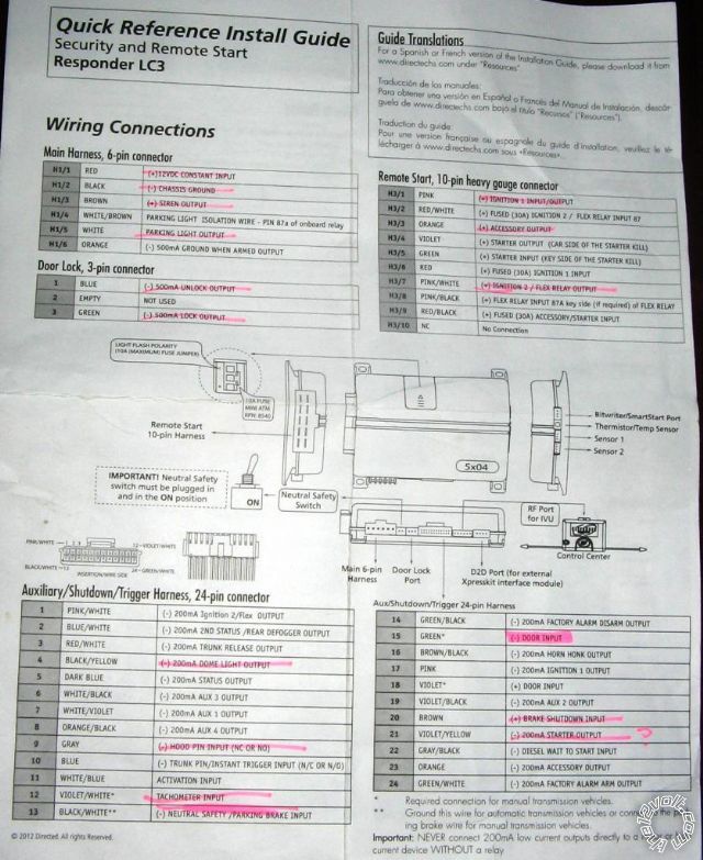
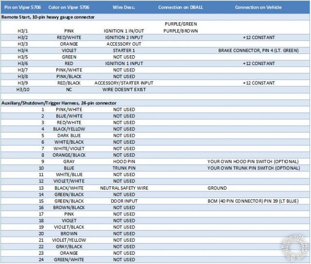
STANDARD VIPER ALARM HARNESS CONNECTORS INCLUDED WITH ALARM (6 pin, 3 pin, 10 pin)
MAIN HARNESS, 6 PIN CONNECTOR
--H1/1 Red (+)Â 12vDC Constant -----> Does this go to Ignition harness?? or Not?
--H1/2 Black (-)Â chassis ground -----> Connect to vehicle factory bolt?? Or NOT?
--H1/3 Brown (+)Â Siren -----> Connect to Siren - + and â to chassis
--H1/4 WHITE/ Brown Parking light isolation wire â---> Not used - D2D
--H1/5 White Parking light output â (+ or -) depending on jumper â---> NOT used - D2D
--H1/6 Orange (-)Â 500mA Ground w? armed output â starter kill circuit â uses relay â--> NOT USED
Door Lock, 3 PIN CONNECTORÂ
--1 Blue (-) 500mA Unlock output -----> Data to data
--2 Empty
--3 Green (-) 500mA lock output ------> Data to daa
REMOTE START, 10 PIN HEAVY GAUGEÂ
---H3/1 Pink (+)Â ignition 1 input/ouput --->
---H3/2 RED / White (+)Â fused (30a) ignition 2 / Flex relay INPUT 87 ---->
---H3/3 Orange (+)Â ACCESSORY output --------> ignition harness??
---H3/4 Violet (+)Â STARTER OUTPUT (car side) [onboard relay â direct connect] -----> Brake Switch (+)
---H3/5 Green (+)Â STARTER INPUT (key side) [onboard relay- direct connect] -----> ?
---H3/6 Red (+)Â fused (30a) IGNITION 1 INPUT ---->
---H3/7 Pink/White (+)Â IGNITION 2 / Flex relay OUTPUT ----> Where????
---H3/8 Pink/Black (+)Â Flex relay INPUT 87a key side (if required) of Flex relay ---------> WHERE???
---H3/9 RED / Black (+)Â fused (30a) ACCESSORY / starter input (POLARITY FEED FOR Accessory/starter input relay) ---------> 12v constant ignition harness??
---H3/10 --->Â No connection ??
[H3/2 RED / WHITE, H3/6 RED, H3/9 RED / BLACK and H1/1 RED are connected to 12v constant]
-------------
Erick
Replies:
Posted By: freqsounds
Date Posted: February 03, 2014 at 8:46 PM
The only wires to connect in D2D mode are in black. The blue dashed lines are for W2W and are not needed. The lock, unlock, and ignition wires are the only ones that need to be connected in D2D from the Viper. Everything else goes through the databus of the DBALL2.
No diodes are needed, but if it's a manual transmission, you will need the two relays depicted in the instructions.
-------------
No question is stupid or not worth asking. You were once a noob, right? :)
Posted By: magnamagus
Date Posted: February 04, 2014 at 1:46 PM
Question:
1. In regards to the "Stater Interrupt", are the (H5)Starter INPUT and (H4) Starter OUTPUT, really necessary OR is this handle by DBALL2 through through it's Starter 1 and Ignition 1 connections???
---H3/4 Violet (+)Â STARTER OUTPUT (car side)
---H3/5 Green (+)Â STARTER INPUT (key side)
2. The 2010 Nissan Maxima has TWO starters and Ignitions: (-) Starters 1 and (-)Starter 2, and, (+)Ignitions 1 and (-) Ignition. Now, the Dball2 Install Guide, says to connect from the DBALL2 only Ignition Input(+) [to Dball2 ignition input & output] and Starter 1 (+) out put [to Brake Wire (+)]? Is this correct? And, does the Dball2 handle the Ignition & Starting sequence entirely through these wires?
Again, thank you for your assistance...
-------------
Erick
Posted By: freqsounds
Date Posted: February 04, 2014 at 4:24 PM
The starter wires aren't used. But you'll need the Ignition 1 input wire from the H3 harness.
When using the DBALL/DBALL2, nevermind the car wiring diagram. Only follow the instructions in the DBALL/DBALL2 installation instructions.
Are you installing W2W or D2D? You can't do both. The starter wires on both the remote start and DBALL are used only in W2W mode. If you have the DBALL firmware loaded, there's no point in using W2W -- it's extra work. D2D allows both units to 'talk' to each other. The DBALL is the middle man that 'talks' to your car as well. Because it can 'talk' to your car, it eliminates a LOT of wires in D2D mode. In W2W, all the wires are required because it has no way to 'talk' to the remote start. So connecting all the wires allows the DBALL to 'monitor' instead of 'talk', allowing it to know what both systems are doing at the same time when using W2W.
So, again, if you're using D2D mode, only use the wires in black. If you're using W2W, the blue-dashed wires need to be connected IN ADDITION TO the black wires. If you're using D2D, disregard the blue-dashed wires.
I hope this helps clear up your questions a bit! If you have any other questions, please describe the mode you are using (W2W or D2D).
-------------
No question is stupid or not worth asking. You were once a noob, right? :)
Posted By: magnamagus
Date Posted: February 05, 2014 at 7:08 AM
D2D - data to data mode will be used to connect the alarm.
Questions: You stated I will need the "Ignition 1 input wire from the H3 harness". I have located H3/1 and H3/6 (below).
---H3/1 Pink (+) ignition 1 input/ouput
---H3/6 Red (+) fused (30a) IGNITION 1 INPUT
1. Do I need to connect the 10 gauge "H3/6 Red fused" to a 12v constant source and then the "H3/1 Pink ignition input/output wire" to the 24 gauge Dball2 "ignition status input/output wires"?
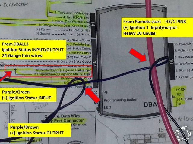
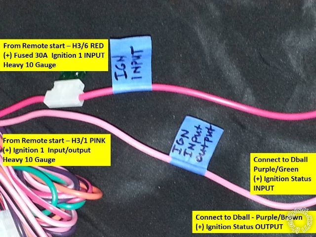 2. I was intending to connect the remote start's heavy 10 gauge "H3/1`Pink Ignition Input/Output" wire TO the DBALL2 24 gauge "Ignition Status Input" and "Ignition status output" wire per the Dball2 install manual (photo). Is this correct?
Photo below: The 'large Red arrows' show were wires are supposed to intersect (dball2 manual). This indicate were I intend to military splice the DBALL2 ignition output(PURPLE / brown) to the ignition input (PURPLE / green) as indicated in the dball2 install diagram. I then intended to military splice the 24 gauge ignition input (PURPLE / green) to the 10 gauge "H3/1 Pink Ignition input/out" wire from the remote start.
2a. Are these connections correct? This seems odd connecting a 24 gauge wire (dball) to a 10 gauge wire (remote start)?
 ------------- Erick
Posted By: freqsounds
Date Posted: February 05, 2014 at 7:47 AM
1. Yes, that'll be connected to 12V constant (+)
2. Yes, those connections are correct.
-------------
No question is stupid or not worth asking. You were once a noob, right? :)
Posted By: magnamagus
Date Posted: February 06, 2014 at 3:59 AM
In regards to your answer:
Therefore, I will connect the remote start's heavy 10 gauge "H3/1`Pink Ignition Input/Output" wire TO the DBALL2's two 24 gauge "Ignition Status Input" and "Ignition status output" wire in the following manner. I will military splice two wires from the DBALL2, these are 24 gauge Ignition output(PURPLE / brown) to the Ignition Input (PURPLE / green) as indicated in the install diagram. Then, I will military splice the 24 gauge ignition input (PURPLE / green) to the 10 gauge "H3/1 Pink Ignition input/out" wire from the 5706 remote start.
Question 1: After the above connections are made to the heavy 10 gauge "H3/1`Pink Ignition Input/Output", does the PINK H3/1 wire need to be connected anywhere else (to the vehicle perhaps) OR is that the final connection i.e. Remote start to Dball2?
Question 2: Is it a good idea to use a diode 1N4001 1N4001, 1N4007 at the BCM for (-) lock & (-)unlock wires to protect the BCM. For example, inserting a diode leg (diode stripe towards the R/S) into the BCM empty pin holes for Lock and Unlock. The diodes leg diameter is the correct size to make solid contact with the BCM connector inside. This will protect the BCM?
Again, thank you for your assistance... Greatly appreciated...
-------------
Erick
Posted By: freqsounds
Date Posted: February 06, 2014 at 6:41 AM
Your splicing sound good. No other connections will be made with the ignition wire.
I recommend hooking up the DBALL to the car and testing the door locks first as per the manual. They're not needed if they're controlled by data. If they are needed, there is no need to diode isolate them.
-------------
No question is stupid or not worth asking. You were once a noob, right? :)
Posted By: magnamagus
Date Posted: February 07, 2014 at 1:48 PM
Great Thank you for you input.... Sorry, but I have another question, that I would like to get clarification on. I have started the install. I have all the wires connected:
Question: The DBALL2 instruction manual says to connect from the remote starter 10 Gauge Violet "STARTER 1 (+) OUTPUT" (car side of the starter kill) to the (+) Brake Wire at the brake pedal which is a 24 gauge wire or thinner?
Can you please verify this connection, is it correct, or does it require a relay?
Thank you for the assistance...
-------------
Erick
Posted By: pentavolvo
Date Posted: February 07, 2014 at 3:31 PM
On that car dball will control door locks via data
Posted By: magnamagus
Date Posted: February 07, 2014 at 6:37 PM
Question: The DBALL2 instruction manual says to connect from the remote starter 10 Gauge Violet "STARTER 1 (+) OUTPUT" (car side of the starter kill) to the (+) Brake Wire at the brake pedal which is a 24 gauge wire or thinner? IS this a correct connection from a 10 gauge to a 24 gauge wire?
-------------
Erick
Posted By: freqsounds
Date Posted: February 07, 2014 at 9:05 PM
Yep, this will simulate someone pressing the brake pedal when pushing the PTS button to start the car. This connection is correct.
-------------
No question is stupid or not worth asking. You were once a noob, right? :)
Posted By: magnamagus
Date Posted: February 08, 2014 at 3:22 AM
I got everything connected that I can think of so far. I wired the viper and dball2 harnesses first and then double checked the connections. I then connected the Python 5706, Shock sensor, antenna, and safety switch. I kept my fingers crossed, and then let her rippp... *LOL*
Positives: I am able to unlock/lock all four doors, Arm/Disarm, Alarm detects door pin, siren chirps and works, key sense seems to work, parking lights work, OEM remote control of Alarm Arm/Disarm. I was also able to reprogram the Manual Transmission factory default to Automatic Mode option #2. I also did Tach Programming.
Negatives:
1. - I still do not have remote start. I get an "REMOTE START ERROR" on the Python Key Fob. The parking light blinks 8 times indicating a neutral safety switch error?
2. - The Double Guard Shock Sensor won't let me adjust it through the python 2-way key fob. The Python 2-way shows a signal being sent to the Python but there is No Signal in return, I get an error "X" failed signal. I tried kicking the tires and NOTHING -- No shock sensor trigger. The alarm does trigger when the door is open though.
Why isn't this Shock sensor working?
3. - Auxiliary Trunk pop - Open is not working on the Python -- I don't know if this was included.
-------------
Erick
Posted By: magnamagus
Date Posted: February 08, 2014 at 3:43 AM
Update: I do have trunk pop through the Python 2-way remote. The Auxiliary needs to be held for a few seconds for this to work.
Problem: The main issue is the "Remote Start Error" which gives me "8 parking light blinks" signifying "Neutral Safety Switch". I did instal the Neutral safety switch (double checked) that came with the python and I switched this to the "ON" position; I also tried the "Off" position and still got the same error. Am I missing a wire somewhere?
-------------
Erick
Posted By: kreg357
Date Posted: February 08, 2014 at 5:41 AM
If going D2D ( using the D2D harness ) between the DB-ALL2 and the Python 5706, the DB-ALL2 sends the vehicles Parking Brake status it collected off the CAN bus to the 5706 via the D2D harness. The 5706 uses this as the Neutral Safety Input signal. Do you have the Maxima's Parking Brake engaged prior to a remote start attempt?
In W2W mode, you would simply connect the 5706's BLACK/ WHITE (-) NEUTRAL SAFETY /PARKING BRAKE INPUT wire ( Pin 13 on the 24 Pin plug ) to chassis ground on vehicles with an automatic transmission. ------------- Soldering is fun!
Posted By: magnamagus
Date Posted: February 09, 2014 at 9:07 AM
Python Install -- The Double Guard Shock Sensor won't let me adjust it through the python 2-way key fob. The Python 2-way shows a signal being sent to the Python but there is No Signal in return, I get an error "X" failed signal. I tried kicking the tires, repeatedly. I have kick very hard to get the alarm to trigger. The alarm does trigger when the door is opened.
Does anyone have any ideas why the Shock sensor isn't letting me program it? Could it be one of the menu settings?
-------------
Erick
Posted By: freqsounds
Date Posted: February 09, 2014 at 10:01 AM
magnamagus wrote:
Python Install -- The Double Guard Shock Sensor won't let me adjust it through the python 2-way key fob. The Python 2-way shows a signal being sent to the Python but there is No Signal in return, I get an error "X" failed signal. I tried kicking the tires, repeatedly. I have kick very hard to get the alarm to trigger. The alarm does trigger when the door is opened.
Does anyone have any ideas why the Shock sensor isn't letting me program it? Could it be one of the menu settings?
Did kreg357 resolve the remote start issue? Also, make sure your little switch is plugged in and in the ON position.
If you have the external shock sensor, like the one below,
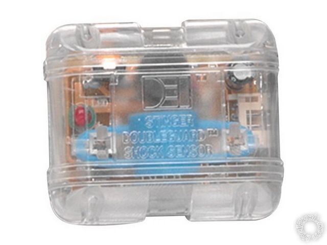
Look on the side of it. You'll see a little hole to access a potentiometer. This is where you make the adjustment on these sensors. Clockwise for more sensitive. Make sure you don't turn it past its stopping point!
What model is the brain? It'll say "Viper" then the model. If it's the 5X04, the sensor is built in and are a pain. They have to be set via the remote or bitwriter. When using the remote, can you get to the settings menu? If I remember correctly, while you're holding function, it'll beep before you get the settings menu. Keep holding and it should get you in.
------------- No question is stupid or not worth asking. You were once a noob, right? :)
Posted By: freqsounds
Date Posted: February 09, 2014 at 10:10 AM
Another tip in my experience:
When you mount the shock sensor, make sure it is kind of loose. If it's tight, it doesn't work as well. I like to dangle the external sensors off the steering column, zip tying the wires to it just before the connector. If it dangles too much (i.e. 3 inches or more) it doesn't work.
-------------
No question is stupid or not worth asking. You were once a noob, right? :)
Posted By: magnamagus
Date Posted: February 18, 2014 at 6:06 AM
I am having issues with the alarm and remote start. I ran the diagnostics: Press python valet/control switch and hold (antenna), turn car ON then OFF, release control switch, then Press the control switch again and release. The LED flashes: 3 times, 5 times, 8 times. I do hear a Clicking sound and then car turns ON then Off.
Code Definitions:
3 Low or no RPM
5 (+) brake
8 (-) Neutral safety shutdown (H3/1 BLACK/ WHITE)
Alarm: VIPER 5706 -- SUPPORTS DATA TO DATA -- REMOTE START + Security
DBALL2 BYPASS INSTALL GUIDE: https://www.xpresskit.com/VehicleCompatibility.aspx?p=null&year=2010&make=Infiniti&model=G37%20%28Smart%20Key%29&ps=1&s=0&c=0
I am using data to data and I have all other functions: Lock/unlock etc.
1. Per DBALL2 Install guide the H3/4 Violet (+)STARTER OUTPUT (car side)is attached to the Brake (+) wire.
-- H3/5 Green (+) STARTER INPUT (key side) --- NOT CONNECTED
2, (-) Neutral Safety Switch plugged in, connected, and turned to ON position.
3. Neutral Safety Parking Brake INPUT -- 24 pin harness BLACK/ WHITE --- is Connected to common ground per python install guide.
4. Low or No RPM ---- What is this?
-------------
Erick
Posted By: freqsounds
Date Posted: February 18, 2014 at 8:07 AM
[QUOTE]
3 Low or no RPM
5 (+) brake
8 (-) Neutral safety shutdown (H3/1 BLACK/ WHITE)
[/QUOTE]
3 - disregard, especially if the remote hasn't worked yet. The virtual tach needs to be learned.
5 - This is the brake input that should be connected to your brake pedal. Make sure you have this hooked up to the correct wire -- it should be connected to the side that is hot when the brake pedal is pressed.
8 - I would double check the connection on this, but addressing/resolving (5) might resolve this code.
[QUOTE]
I am using data to data and I have all other functions: Lock/unlock etc.
1. Per DBALL2 Install guide the H3/4 Violet (+)STARTER OUTPUT (car side)is attached to the Brake (+) wire.
-- H3/5 Green (+) STARTER INPUT (key side) --- NOT CONNECTED
2, (-) Neutral Safety Switch plugged in, connected, and turned to ON position.
3. Neutral Safety Parking Brake INPUT -- 24 pin harness BLACK/ WHITE --- is Connected to common ground per python install guide.
4. Low or No RPM ---- What is this?
[/QUOTE]
1. Yes, the violet starter wire from the remote start is connected to the Lt. Green wire, pin 4 on the brake switch. The green from the remote start should not be connected. Make sure Ign1 input is connected (it's best practice to take all the fused heavy gauge wires and latch them to +12V Constant). These wires provide the +12V to relays inside the remote start system, so if they're not hooked up, half the box might be dead.
2, 3. You have the correct wire, and it should be connected to common ground. Maybe double check the connection and verify there is, in fact, ground where you have it connected. I can't tell you the number of times I connected ground to a metal plate that wasn't grounded! 
4. Again, worry about this code after you get the car started, it could be a false positive. ------------- No question is stupid or not worth asking. You were once a noob, right? :)
Posted By: magnamagus
Date Posted: February 18, 2014 at 12:38 PM
 ------------- Erick
Posted By: freqsounds
Date Posted: February 18, 2014 at 1:14 PM
Check H3/9 and make sure it has +12V ------------- No question is stupid or not worth asking. You were once a noob, right? :)
Posted By: harryharris
Date Posted: February 19, 2014 at 9:59 AM
I may have missed something here but two thoughts:
Did you learn tach?
Also sometimes the DB-ALL doesn't do what it says on the label!
I've often had to hard wire stuff as an after thought.
I would separately ground the BLACK/ white at H2/13.
Does it start if you leave the key in the ignition?
Dome light supervision isn't required on current Toyotas.
The vehicle as most Hondas and BMWs has it built in.
-------------
Test before boxing up.
Posted By: freqsounds
Date Posted: February 19, 2014 at 10:04 AM
harryharris wrote:
I may have missed something here but two thoughts:
Did you learn tach?
Also sometimes the DB-ALL doesn't do what it says on the label!
I've often had to hard wire stuff as an after thought.
I would separately ground the BLACK/ white at H2/13.
Does it start if you leave the key in the ignition?
Dome light supervision isn't required on current Toyotas.
The vehicle as most Hondas and BMWs has it built in.
I don't mean any disrespect, but do you actually read the posts before replying?
He has a Nissan Maxima, and the feedback from the question I had about the bypass module are off topic. ------------- No question is stupid or not worth asking. You were once a noob, right? :)
Posted By: harryharris
Date Posted: February 19, 2014 at 10:07 AM
Sorry but I skimmed through and saw nothing to do with tach learning, I lost it completely thinking it was a Toyota..oops.
But still begging the question at this stage how many clicks/LED flashes are we getting on the failure diagnostics?
-------------
Test before boxing up.
Posted By: freqsounds
Date Posted: February 19, 2014 at 10:16 AM
magnamagus wrote:
I do hear a Clicking sound and then car turns ON then Off.
The starter isn't engaging, no error code. ------------- No question is stupid or not worth asking. You were once a noob, right? :)
Posted By: harryharris
Date Posted: February 19, 2014 at 10:37 AM
"I do hear a clicking sound"
Please count the number of clicks and let us know.
Out of interest I never use that override switch I either join the wires together or solder across the port.
Also I would solder all of the joints, then heat shrink the butt joints or use Scotch 33+ or similar over Y joints after testing.
-------------
Test before boxing up.
Posted By: magnamagus
Date Posted: March 12, 2014 at 3:07 AM
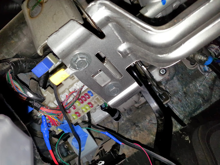
This is a overall picture of 2010 Nissan Maxima dash. The side panel pops off with no bolts. The bottom panel has one screw holding it behind the fuse cover. Remove the screw and it pops off as well.
[ All connections were military spliced with no solder, blue 3M Tape, just in case I need to remove this alarm later]
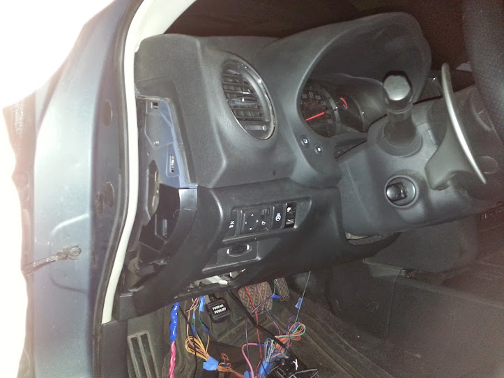
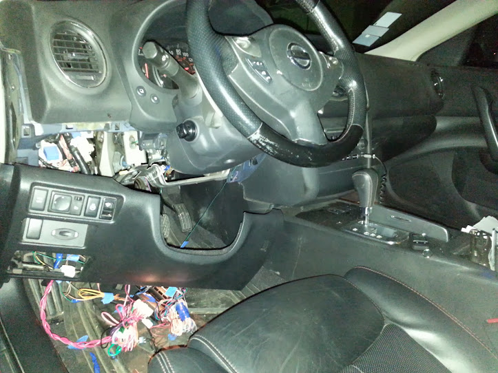 BCM SOLUTION (Alternative to removing BCM)- I did not remove the BCM due to factory tamper proof security screws, very tight space, and fear of damaging the BCM. The BCM is extremely difficult to remove. I followed the wires from the BCM instead
12v constant -
BCM SOLUTION (Alternative to removing BCM)- I did not remove the BCM due to factory tamper proof security screws, very tight space, and fear of damaging the BCM. The BCM is extremely difficult to remove. I followed the wires from the BCM instead
12v constant - I tapped into the 12v constant (WHITE/ Black wire) at harness coming from the BCM module to the fuse box, rather than at the BCM itself. (isolated with multimeter - military spliced)
Door Input - The green wire below coming out of the kick panel, is connected to the door pin underneath the kick panel, rather than at the BCM itself. I isolated this by testing for continuity from the door pin switch to the wire also military spliced.
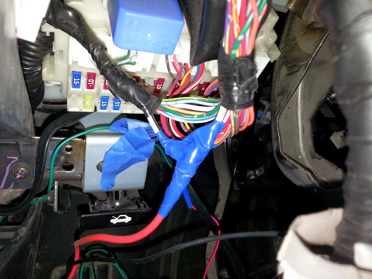 Ground -
 Connected at the bracket under the steering column. Tested with a multimeter and connected with yellow screw type connector.
 Siren -
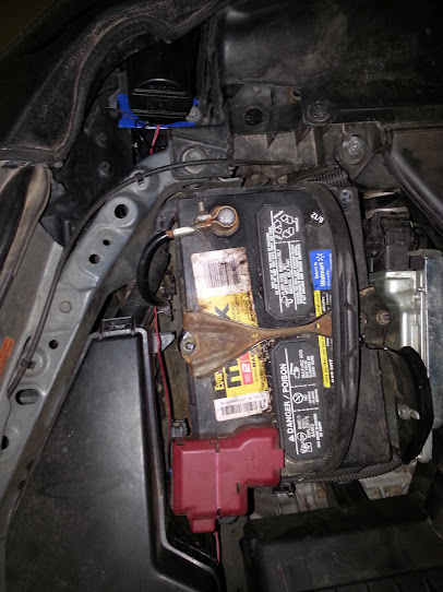
 Mounted in front of battery at the front end. Wire was run through the rubber seal at the steering column. The wire harness was extremely difficult to get to.
 Python Remote START -
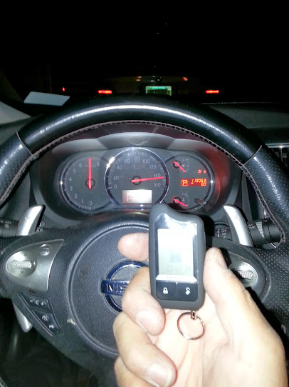
 First start, I received errors and clicking sounds only. All 12v Constant fused wires needed to be connected, Accessory, ignition Inputs, etc. Second Start attempt, I got a "Manual transmission Error" and then a "Hood Open error". This was resolved by programming the python using the Python Remote, switching factory default from "Manual Trans" to "Automatic Transmission". I got a "hood open error" after a few starts. The factory default for the Hood Pin is 'normally open'. I kept getting an "hood open error" until reset it to "normally close" and then back to "normally open" again using the remote for programming. REMOTE START NOW WORKS FINE.... vrooom... *LOL*
 ------------- Erick
Posted By: magnamagus
Date Posted: March 12, 2014 at 3:15 AM
PROBLEM -- The SHOCK SENSOR is set to a very Low level and it will not let me adjust the sensitivity. I turned the shock sensor screw to its highest level and still do not have sensitive alarm trigger. I tried setting the shock sensor using the Python Remote but the remote won't allow me to adjust it.
Does anyone have any ideas on how to solve this shock sensor problem?
-------------
Erick
Posted By: freqsounds
Date Posted: March 12, 2014 at 6:40 AM
Use the loop on the ribbon to dangle it from a wire with a zip tie. Make sure it has enough room to sway back and forth so the wind doesn't set it off. Turn the potentiometer all the way clockwise.
This is going to let the vibrations travel through the wires to the shock sensor without picking up rocking from wind.
-------------
No question is stupid or not worth asking. You were once a noob, right? :)
Posted By: harryharris
Date Posted: March 12, 2014 at 10:22 AM
Also if it's working you'll see a red LED illuminate during the above process.
-------------
Test before boxing up.
Posted By: metz35
Date Posted: March 15, 2014 at 2:37 PM
I have the same vehicle.
1. Turn off engine checking in the options.
2. Change from tach to crank time in options.
3. Change crank time to the max in options.
Since the starter wire is connected to the brake. There is no need for tach. The brake needs to see 12v for a minimum of 2 seconds before it cranks. Thats why we turn up crank time.
let me know if you need any help
Posted By: magnamagus
Date Posted: April 16, 2014 at 1:29 AM
Shock Sensor Fix --
(1)--I tried connecting the shock sensor to a bundle of wires using a zip tie. I then tested the sensitivity by kicking the tires and bumping the vehicle. There was no reaction except when hit very hard.
(2)-- I connected the shock sensor to the hollow vent or air duck inside the cab of the vehicle. I think tested the sensitivity by kicking the tires and hitting the vehicle. The alarm is now triggered when kicked or bumped somewhat firm. This is better in sensitivity.
Question -- Does anyone have any suggestions on how to attach a sensor to maximize its sensitivity? Does anyone have any photos?
-------------
Erick
Posted By: freqsounds
Date Posted: April 18, 2014 at 10:46 PM
Did you adjust the shock sensor's setting?
Dangle the sensor with a zip tie from a wire harness (use the loop on the sensor's harness OR a zip tie tightly about an inch away from the connector -- sensor side). If it's tight, it's hard to trip. If it dangles, it can move and trip. It'll 'feel' the vibrations better.
-------------
No question is stupid or not worth asking. You were once a noob, right? :)
Posted By: dksob81
Date Posted: November 02, 2014 at 10:25 AM
Quick Question...
I have a 2006 Dodge Ram that I am putting a Viper 5904 Remote start in, with a DBALL2 (w/ T-Harness).
The door locks work from the Viper Remote. However it will not remote start, NO ERROR codes or anything, originally I wass getting ERROR Code 6 (HOOD PIN) this was because I had the switch on the DBALL2 T-Harness in the ON position. after I shut that off, it no longer gives me any error codes. It does receive the signal from the remote, the fuel pump kicks on and nothing (no attempt to crank the engine). Also no dash lights either.
Posted By: dksob81
Date Posted: November 03, 2014 at 6:18 AM
Well Apparently I cannot use the T-Harness on my truck. I was reading through the installation type chart and there are 2 types for my truck (Type 3 or Type 4) depending on wether or not there is a start wire (pin 4) at the ignition switch. Mine has the wire so I had to hard wire the DBALL2 to the vehicle. (not too difficult though, on a few wires)
Well now the vehicle will start, but immediately shuts off. Seems like a security issue. I Reset & Reprogrammed the module (per the instructions). Still no go. I connected the tach wire, and I get Error Code 8 (Hood Pin) which is weird, but if I disconnect it, it will start and die immediately.
Any Suggestions? I know this is an old post and I appologize for piggybacking on it
Posted By: freqsounds
Date Posted: November 03, 2014 at 7:18 AM
Your installation is much different than than a Maxima. I would recommend creating your own thread for this issue per the rules of the forum.
-------------
No question is stupid or not worth asking. You were once a noob, right? :)
Posted By: magnamagus
Date Posted: November 03, 2014 at 10:08 AM
Its probably a TACH issue. The 5904 has settings preset by directed electronics. To adjust some of the settings you will need the directed hand held gadget-don't recall the devices name. Authorized directed dealers have these hand held computers, they may let you adjust it yourself OR use it. Also, learning tachometer, Tachometer wiring, vehicle immobilizer, etc. current Firmware for the dball? OR maybe even switching over to a fortin bypass module --- i hear the dball sometimes has issues with certain vehicles.
-------------
Erick
Posted By: wiz6114
Date Posted: November 16, 2014 at 5:12 PM
I am trying to install a viper 2 way system in to a 2014 maxima. I really need a wiring diagram to help me out. And imma replace the factory amplifier and install a new one along with new speakers, so can someone help me out with the wiring diagram.
Posted By: foja
Date Posted: May 27, 2015 at 11:02 PM
I want to help me with the installation for a 2014 jeep compass sport have dball2 and viper5906v. but I do not know what will dball2 wiring the car. They go to the dball2 viper5906v. Help me with a diagram please. I can pay you via PayPal
|